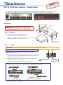
Extron electronic XTP PI 400 is a midspan power injector for XTP products, providing power over LAN for up to four XTP endpoints. It allows for flexible system design and remote powering of XTP devices, making it suitable for various AV installations such as conference rooms, classrooms, and auditoriums. The XTP PI 400 supports a wide range of XTP devices, including transmitters, receivers, and matrix switchers. Its compact size and rack-mountable design enable easy integration into existing systems.
Extron electronic XTP PI 400 is a midspan power injector for XTP products, providing power over LAN for up to four XTP endpoints. It allows for flexible system design and remote powering of XTP devices, making it suitable for various AV installations such as conference rooms, classrooms, and auditoriums. The XTP PI 400 supports a wide range of XTP devices, including transmitters, receivers, and matrix switchers. Its compact size and rack-mountable design enable easy integration into existing systems.


-
 1
1
-
 2
2
-
 3
3
-
 4
4


Extron electronic XTP PI 400 User manual
- Type
- User manual
- This manual is also suitable for
Extron electronic XTP PI 400 is a midspan power injector for XTP products, providing power over LAN for up to four XTP endpoints. It allows for flexible system design and remote powering of XTP devices, making it suitable for various AV installations such as conference rooms, classrooms, and auditoriums. The XTP PI 400 supports a wide range of XTP devices, including transmitters, receivers, and matrix switchers. Its compact size and rack-mountable design enable easy integration into existing systems.
Ask a question and I''ll find the answer in the document
Finding information in a document is now easier with AI
Related papers


Other documents
-
 Extron electronics XTP PI 400 User manual
-
Extron XTP PI 400 User manual
-
Extron XTP PI 100 User manual
-
-
-
Extron XTP II CrossPoint 6400 User manual
-
Extron electronics DTP CrossPoint 86 4K User manual
-
-
-
