2
IN1806 • Setup Guide (Continued)
Step 3 — Connect outputs
Make the following output connections as needed:
• Connect an HDMI, or DVI with an appropriate adapter, display to HDMI/CEC output connector 1A (see figure 1,
D
, on the
previous page). Connect a display to the HDMI Loop Out connector (
C
).
• Connect a DTP/XTP matrix switcher/HDBaseT compatible receiver to output connector 1B (
E
). For cable wiring and
recommendations, see “Twisted Pair Recommendations for DTP, XTP, and HDBaseT Communication.”
• Connect balanced or unbalanced analog audio output devices to one or both 5-pole captive screw output connector pairs 1
and 2, or 3 and 4 (
I
) (see Audio Wiring on the next page for more information).
To pass infrared data, connect a control device to the 3-pole IR Over DTP captive screw connector (see IR Over TP Wiring,
on the next page). Alternatively, insert RS-232 communication to a DTP/HDBaseT endpoint via Ethernet (see the IN1806 and
IN1808 Series User Guide for more information).
Step 4 — Connect control devices
• To control the IN1806 through Ethernet, connect a LAN or WAN to the RJ-45 LAN connector (
J
). To wire the RJ-45
connector to the cable, see “Twisted Pair Recommendations for DTP, XTP, and HDBaseT Communication.” The default IP
address of the scaler is 192.168.254.254, the default subnet mask is 255.255.255.0, and the default gateway address is
0.0.0.0.
• For serial RS-232 control, connect a host device to the 3-pole captive screw connector (
K
). The default baud rate is 9600.
• For control through USB, connect a host device to the front panel USB mini-B port (see figure 2,
A
, on the next page).
Step 5 — Connect power
Connect a 100 to 240 VAC, 50-60 Hz power source to the AC power connector (see figure 1,
A
, on the previous page).
Twisted Pair Recommendations for DTP, XTP, and
HDBaseT Communication
Extron recommends using the following practices to achieve full transmission distances
and reduce transmission errors:
• Use Extron XTP/DTP 24 SF/UTP cable for the best performance. At a minimum,
Extron recommends 24 AWG, solid conductor, STP cable with a minimum bandwidth
of 400 MHz.
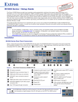
• Terminate cables with shielded connectors to the TIA/EIA-T568B standard (shown at
right).
• Limit the use of more than two pass-through points, which may include patch points,
punch down connectors, couplers, and power injectors. If these pass-through points
are required, use shielded couplers and punch down connectors.
ATTENTION:
• Do not connect these connectors to a computer or telecommunications network.
• Ne connectez pas ces ports à des données informatiques ou à un réseau de télécommunications.
• DTP remote power is intended for indoor use only. No part of the network that uses DTP remote power should be
routed outdoors.
• L’alimentation DTP à distance est destiné à une utilisation en intérieur seulement. Aucune partie du réseau qui utilise
l’alimentation DTP à distance ne peut être routée en extérieur.
NOTE: When using shielded twisted pair cable in bundles or conduits, consider the following:
• Do not exceed 40% fill capacity in conduits.
• Do not comb the cable for the first 20 meters, where cables are straightened, aligned, and secured in tight bundles.
• Loosely place cables and limit the use of tie wraps or hook-and-loop fasteners.
• Separate twisted pair cables from AC power cables.
Firmware Updates
Download rmware updates from the Extron website and upload them via the internal web pages or PCS.
TIA/EIA-T568B
Pin Wire Color
1 White-orange
2 Orange
3 White-green
4 Blue
5 White-blue
6 Green
7 White-brown
8 Brown
12345678
RJ-45
Insert Twisted
Pair Wires