Page is loading ...

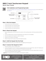
INSTALLATION AND PROGRAMMING GUIDE
8860
7-Inch Touchscreen Keypad

Program Keypad Options ................ 8
Keypad Options Menu..................................8
Wi-Fi Settings .................................................8
Brightness & Volume ....................................8
Carousel Menu ................................................8
Installer Options .............................................8
Keypad Information ......................................8
Set Arm/Disarm Snapshot .........................8
Connect the Keypad to Wi-Fi ......... 9
Connect the Keypad to Wi-Fi ........................ 9
Update the Keypad Locally ............................ 9
Update the Keypad Remotely........................ 9
Live View ................................................................ 9
Recorded View ....................................................10
Recorded Clips ....................................................10
Snapshot Verification Events ........................10
Connect the Video Doorbell ...........................11
Upload a Logo ......................................................11
Dealer Information Screen ..............................11
Program Z-Wave Devices ...............12
Z-Wave Lights ................................................12
Z-Wave Doors .................................................12
Z-Wave Thermostat ...................................... 12
Z-Wave Appliances ......................................12
Z-Wave Favorites ..........................................12
Train Your Customers ......................13
Access the User Menu ......................................13
Arm and Disarm the System ..........................13
Area System Type .........................................13
All/Perimeter System Type .......................13
Home/Sleep/Away System Type ............. 13
Home/Away System Type ..........................13
CONTENTS
Get Started ......................................... 1
What’s Included .....................................................1
What You’ll Need ..................................................1
Procedure .................................................................1
Install the Keypad ............................. 2
Run Wire ..................................................................2
Mount the Keypad ...............................................2
Wire the Keypad...................................................2
Use the Keypad ................................. 4
Keypad Layout ..................................................... 4
Enter Characters ................................................. 4
Standard Keyboard ....................................... 4
Program the Panel ............................ 5
Device Setup.................................................... 5
Device Number ............................................... 5
Device Name ................................................... 5
Device Type ...................................................... 5
Communication Type ................................... 5
Program the Keypad ........................ 6
Installer Options .............................................6
Set Panic Buttons ..........................................6
Set Keypad Address .....................................6
Set Default Keypad Message .....................6
Check for Updates .........................................6
Program the Carousel Menu ........... 7
Carousel Z-Wave Items ................................ 7
Carousel Shortcut Items .............................. 7

Change System Wi-Fi Password ..................14
Clean the Keypad ...............................................14
Icons ........................................................................ 15
Reference .......................................... 16
Keypad Bus Wiring Specifications ..............16
Compatibility .......................................................16
Ordering Information .......................................16
Keypads ............................................................16
Specifications ...................................17
Certifications ....................................17
FCC Information ................................................. 17

8860 Installation and Programming Guide | Digital Monitoring Products 1
GET STARTED
8860 7-Inch Touchscreen Keypads oer an easy to use touchscreen interface with an on-board camera, optional
panic keys, an internal speaker, a simple terminal connection to a 4-wire keypad bus, and other features. The 8860 has
enhanced Wi-Fi communications to Dealer Admin™ for video system integration and image capture when arming and
disarming at the keypad. Keypads can be mounted on a flat surface with appropriate fasteners.
What’s Included
▶One 8860 7-Inch Touchscreen Keypad
▶Hardware pack
What You’ll Need
▶7/64” (2.5mm) drill bit for drywall mounting
▶1/4” (6 mm) drill bit for masonry mounting
▶#2 Phillips screwdriver
Procedure
This guide walks you through the required steps needed to install an 8860 keypad. They are:
1. Install the keypad.
2. Use the keypad.
3. Program the panel.
4. Program the keypad.
5. Program the carousel menu.
6. Program keypad options.
7. Connect the keypad to Wi-Fi.
8. Program Z-Wave devices.
9. Train your customers.

8860 Installation and Programming Guide | Digital Monitoring Products 2
INSTALL THE KEYPAD
1 Run Wire
Run wire from the power source to the keypad mounting location. See Keypad Bus Wiring Specifications section
on page 16 for maximum wire runs.
Mount the Keypad
1. Route the keypad wires through the cutouts in
the base. See Figure 1.
2. Use the keypad base to mark the holes for the
screws on the mounting surface. The base should
be placed at standing height and the hooks on
the base should be facing up.
3. Set the base aside and drill the holes.
4. Use the included screws to secure the keypad
base to the surface. Do not overtighten.
5. Attach the wire harness to the keypad.
6. Slide the keypad onto the base and press the
keypad into place. The on-board camera should
be on the left.
2
TOP
BOTTOM
Figure 1: Mounting Hole Locations
3 Wire the Keypad
To wire the keypad to the panel, make the connections shown in Figure 2.
Caution: Disconnect all power before wiring. Failure to do so may result in equipment damage or injury.
Observe polarity when making power connections.
1. Connect the red wire to panel terminal 7.
2. Connect the yellow wire to panel terminal 8.
3. Connect the green wire to panel terminal 9.
4. Connect the black wire to panel terminal 10.
WIRE COLOR PURPOSE
Black Ground from Panel*
Green Receive Data from Panel*
Yellow Send Data from Panel*
Red Power from Panel or Auxiliary Power Source*
*Required connections
Note: The keypad bus on a typical system can power up to four 8860 keypads on an XR panel and no more
than one 8860 on an XT panel without the use of an external power supply. DMP recommends performing
system power calculations before installing more than one device on the keypad bus.

8860 Installation and Programming Guide | Digital Monitoring Products 3
Black - Ground
Green - Receive Data
To Panel
Keypad Bus Yellow - Send Data
Red - Power
Keypad
Back
Figure 2: Keypad Wiring

8860 Installation and Programming Guide | Digital Monitoring Products 4
USE THE KEYPAD
Enter Characters
To see how to enter characters, watch the video How to Type on a Keypad.
Standard Keyboard
▶Press ABC to enter uppercase letters.
▶Press abc to enter lowercase letters.
▶Press !@# to enter special characters.
▶Press 123 to enter numbers and to return to the number pad.
Select Areas
Return to
Home Screen
Figure 4: Number Pad Figure 5: Standard Keyboard
Number Pad
Uppercase/
Lowercase
Letters
Special
Characters
Keypad Layout
Figure 3: Keypad Layout
Dealer Logo
Carousel Menu
Local
Weather
Interactive
Arming/
Disarming
Home Shield
Drag the menu
to scroll
Drag down the attention
list to view events

8860 Installation and Programming Guide | Digital Monitoring Products 5
PROGRAM THE PANEL
Before continuing with programming and setup, program the keypad in the panel as a device.
To access the Programmer menu, reset the panel by shorting the RESET header, press Keypad in the Carousel menu,
enter 6653 (PROG), then press CMD.
After completing each of the following steps, press CMD to advance to the next option. To exit the Programmer menu,
tap CMD to advance through the menu items until you reach the end of the menu. At the end of the menu, press the
back button twice to return to the main screen. Refer to the panel programming guide as needed.
Device Setup
Advance to Device Setup, then press a select area to enter the setup menu.
Device Number
Set the keypad address.
Panel Models Compatible Device Numbers
XR550 1 - 16
XR150 1 - 8
XT30/XT50 1 - 8
Device Name
Enter a name for the device.
Device Type
For use as a standard keypad, select KPD.
Communication Type
Ensure the COMM TYPE is set to KPD (Keypad Bus).
Configure additional options as needed.
DEVICE SETUP
DEVICE SETUP
DEVICE NO: -
DEVICE SETUP
*UNUSED*
DEVICE SETUP
TYPE: KEYPAD
DEVICE SETUP
COMM TYPE: KPD

8860 Installation and Programming Guide | Digital Monitoring Products 6
PROGRAM THE KEYPAD
To access the Keypad Installer Options menu, press Options in the Carousel menu. Tap the Installer Options wrench icon,
enter 3577 (INST), then press CMD.
Installer Options
To program keypad options, press the Installer Options wrench icon and enter 3577
(INST). Press CMD. Select an option to configure its settings. Press the back arrow to
back out of the menu.
Set Panic Buttons
Use this option to enable or disable the panic keys. Select the panic buttons you would
like to have displayed on the keypad. Once the panic option is enabled, a check mark
displays next to the selected options.
Set Keypad Address
Set the current keypad address to be the same as the panel device number. The default
address is set at 01. To change the current address, press any select area to clear the
keypad display, enter the new address, and press CMD. It’s not necessary to enter a
leading zero for addresses 1 to 9.
Set Default Keypad Message
Enter a custom message of up to sixteen characters to appear at the top of the keypad
display. Press any select area, enter a new message, and press CMD. If a message has
been entered, it will display in the field until changed.
Check for Updates
The keypad has local and remote update capabilities. The keypad must be connected to
Wi-Fi to perform a local and remote update. The remote update capabilities can be used
for per device updates through Dealer Admin™.

8860 Installation and Programming Guide | Digital Monitoring Products 7
PROGRAM THE CAROUSEL MENU
The Carousel menu allows the user to pick and choose what displays within the Carousel menu on the home screen.
Press Options in the Carousel menu. Tap the Installer Options wrench icon, enter 3577 (INST), then press CMD. From
here, select Carousel Z-Wave Items or Carousel Shortcut Items to configure their settings.
Carousel Z-Wave Items
Carousel Z-Wave Items allows you to select the Z-Wave options to display in the
Carousel menu. Press an item to select and a check mark displays. Press again to
deselect that option. Items for the Carousel include Lights, Doors, Thermostats,
Appliances, and Favorites. Press the back arrow to return to the previous screen. Default
is no items selected.
Carousel Shortcut Items
Carousel Shortcut Items allows you to select additional menu items to display in the
Carousel menu. Press an item to select and a check mark displays. Press again to
deselect that option. Items for the Carousel include User Codes, Schedules, Events, and
Bypass. Default is no items selected. Select Edit Favorites to display the Edit Z-Wave
icon on the Favorites screen. Select Edit Z-Wave to display the Edit Z-Wave icon for the
Lights, Doors, Thermostats, and Appliances screens.

8860 Installation and Programming Guide | Digital Monitoring Products 8
PROGRAM KEYPAD OPTIONS
The Keypad Options menu allows the user to view and change their keypad settings. Press Options in the Carousel
menu. Tap the Installer Options wrench icon, enter 3577 (INST), then press CMD. Tap each option to configure their
settings.
Keypad Options Menu
The keypad options menu allows the user to view and change their keypad settings.
These options include Wi-Fi Settings, Brightness & Volume, Clean Screen, Carousel
Menu, Installer Options, and Keypad Information.
Wi-Fi Settings
The keypad needs to be connected to the Wi-Fi network to access remote updates and
video features. Tap the network you want the keypad to connect to. Enter the Wi-Fi
network password and press CMD.
Brightness & Volume
Drag the bar to the right to increase the brightness and volume of the keypad button
press sound and keypad chime sound. Drag the bar to the right to decrease the
brightness and volume of the keypad button press sound and keypad chime sound.
Press the back arrow to go back to the keypad options menu.
Carousel Menu
Press each option in this menu to display the option in the Carousel menu. A check
mark will display next to the option if it is selected to display in the Carousel menu. The
options include Chime, Reset, and Easy Exit.
Installer Options
Select this option to open the Installer Options menu. This menu allows you set keypad
options.
Keypad Information
Select this option to see the keypad model number and current firmware version. Press
Ok to return to the previous menu.
Set Arm/Disarm Snapshot
Select this option to enable or disable Snapshot Verification Events at the keypad during
an Arming or Disarming event. Default is On.

8860 Installation and Programming Guide | Digital Monitoring Products 9
CONNECT THE KEYPAD TO WI-FI
Connecting the keypad to Wi-Fi allows you to use video features with your keypad. DMP video features and events are
available on the 8860 keypad and the Virtual Keypad mobile device app.
Note: Videos are not stored locally on the keypad.
Connect the Keypad to Wi-Fi
1. Select Options from the Carousel menu.
2. Select Wi-Fi Settings.
3. Select the Wi-Fi network you would like to connect to.
4. Enter the password and select CMD.
Note: The keypad needs to be connected to Wi-Fi to enable video features and remote update capabilities.
Update the Keypad Locally
1. Connect the keypad to the Wi-Fi network before proceeding.
2. Select Options from the Carousel menu, then select Installer Options.
3. Enter 3577 and enter CMD. Select Check for Updates. Follow the on-screen prompts to complete update.
Update the Keypad Remotely
1. Navigate to Dealer Admin™.
2. Select the user and system.
3. Next to the keypad name, select Update.
Live View
This function allows you to see all system cameras added in Dealer Admin™.
Note: Visible on Keypad must be toggled On in Dealer Admin™ for each
camera to be added to the Camera List.
1. In the Carousel menu, tap Video.
2. Select a camera to display on the keypad.
3. Swipe the screen left to go to the next camera. Swipe the screen right
to go to the previous camera. Pinch to zoom.

8860 Installation and Programming Guide | Digital Monitoring Products 10
Recorded View
This function allows you to access recorded video events through the events list on the keypad.
1. In the Carousel menu, tap Video.
2. Select a camera to display on the keypad.
3. Press the Video Clips button in the bottom right corner of the keypad
screen.
4. Toggle the play/pause button to play or pause the clip. Press the
speaker button and drag the bar up and down to increase or decrease
the volume.
5. Swipe the screen left to go to the next clip. Swipe the screen right to
go to the previous clip. Pinch to zoom.
6. Press Protect Clip in the bottom right corner of the keypad screen to prevent the clip from being erased.
Recorded Clips
This function allows you to access recorded video events through the events
list on the keypad.
1. In the Carousel menu, tap Events.
2. Tap a row to select an event.
3. Swipe the screen left to go to the next event. Swipe the screen right
to go to the previous event. Pinch to zoom.
Snapshot Verification Events
This function allows you to see a snapshot from the keypad front facing
camera during an arming or disarming event. You can view snapshot events
in Events on the keypad or through Event History on Virtual Keypad.
1. In the Carousel menu, tap Events.
2. Tap a row to select an event.
3. Swipe the screen left to go to the next event. Swipe the screen right
to go to the previous event. Tap the Info icon to display the Event
Information Banner.
4. Tap the Filter icon to display the Filter Events menu. Use the Filter By
section on the left side of the screen to change how the events are
categorized. The categories include Type, Camera, Users, Dates, and
Areas. Tap Apply to activate the filter in the Events List.
5. After a filter is activated in the Events List, a horizontally scrollable
banner will display the applied filters. To remove an individual filter,
press the X on each filter.

8860 Installation and Programming Guide | Digital Monitoring Products 11
Connect the Video Doorbell
Note: The 8860 supports one doorbell per system. Video doorbell
capabilities are only available for the DMP Model V-4061DB Video
Doorbell.
1. In the Carousel menu, tap Video Doorbell.
2. Press and hold the Talk button to talk through the keypad. Tap the
Speaker button to mute and unmute the incoming audio. Tap the End
button to end the video feed and go back to the Home Screen.
Upload a Logo
To upload a logo to your 8860, complete the following steps in Dealer Admin.
Note: For best results, logos should be a 240 x 100 pixel PNG file with a transparent background.
1. In the menu, go to Settings > Dealer.
2. Open the Logos tab.
3. In the Dark Background section, select Upload.
4. A file upload dialog opens. Select the logo that you want to upload and select Open. To preview your logo, select
Preview.
5. Select Save.
Note: If your logo does not load on its own, press the DMP logo on the 8860 keypad. This will trigger the keypad to
reach out to Dealer Admin for the new logo.
Dealer Information Screen
Information from the following lines in the Dealer Admin Account Information section will populate on the 8860’s Dealer
Info screen.
▶Street 1
▶Street 2
▶Phone 1
▶Phone 2
▶Email
▶Website

8860 Installation and Programming Guide | Digital Monitoring Products 12
PROGRAM Z-WAVE DEVICES
The Z-Wave menu allows the user to operate their Z-Wave home automation devices at the keypad. Press Z-Wave
categories such as Lights, Doors, Thermostats, Appliances, and Favorites in the Carousel menu to configure their
settings.
In the Carousel menu, press Favorites or select a Z-Wave device. Then, tap the Settings icon in the bottom right corner
to configure device settings.
Note: Z-Wave Lights, Doors, Thermostats, Appliances, and Favorites must be enabled in the Carousel Shortcut
Items list to configure Z-Wave settings.
Z-Wave Lights
Z-Wave lights can be turned on and o at the keypad. Use the multilevel slider on the
right side of the light to set the light at 0, 25, 50, 75, or 100. 0 is O and 100 is On. To
reset the metered switch for a light, press RESET underneath the light you want to reset.
Z-Wave Doors
Z-Wave doors can be locked or unlocked at the keypad. The keypad will show the lock
battery level next to the door the lock is assigned to. The garage door icon animates as
it is opening or closing. Press Open or Close to activate the garage door animation.
Z-Wave Thermostat
Z-Wave thermostats can be controlled at the keypad. Use the slider handles or the
setpoint increase and decrease buttons to change the temperature. When there are
multiple Z-Wave thermostats on a system, swipe the screen to the left to access
additional thermostats.
Z-Wave Appliances
Z-Wave appliances can be turned on or o at the keypad. Use the multilevel slider on
the right side of the light to set the light at 0, 25, 50, 75, or 100. 0 is O and 100 is On.
Z-Wave Favorites
Z-Wave favorites can be assigned at the keypad. Press Activate next to the name of the
favorite that you want to activate. The name of the favorite will change to Activated
after the process is complete.

8860 Installation and Programming Guide | Digital Monitoring Products 13
TRAIN YOUR CUSTOMERS
This section contains instructions on how users can access the user menu, arm and disarm their system, change the
system Wi-Fi password, and clean the keypad. All of the examples displayed assume that CLOSING CODE is YES in panel
programming.
For more information about using your system, refer to the appropriate system user guide.
Access the User Menu
1. In the Carousel menu, select Keypad.
2. Tap CMD to advance to MENU? NO YES. Tap YES.
3. Enter your user code, then tap CMD.
4. Tap CMD to advance through the menu items. To enter a menu, tap any select area.
Arm and Disarm the System
Area System Type
1. Press and release the shield to open the arming options screen. Tap your preferred
option.
2. If arming, the keypad displays ALL? NO YES. Select NO to arm individual areas. Tap
the area name and then select Arm Selected at the right of the screen. To arm all
areas, select Arm All at the right of the screen.
3. If disarming, the keypad displays ENTER CODE. Enter your user code. The keypad
will display ALL? NO YES. Select NO to arm individual areas. Tap the area name and
then select Disarm Selected at the right of the screen. To disarm all areas, select
Disarm All at the right of the screen.
All/Perimeter System Type
1. Tap the home screen shield in the center of the keypad.
2. If arming, select ALL to arm all areas or PERIM to arm only the perimeter. If ENTER
CODE displays, enter a user code at the keypad.
3. If disarming, enter a user code at ENTER CODE.
Home/Sleep/Away System Type
1. Tap the home screen shield in the center of the keypad.
2. If arming, HOME SLEEP AWAY displays. Select HOME to arm the perimeter, select
SLEEP to arm everything except the bedroom areas, or select AWAY to arm all
areas. If a selection is not made, all areas will automatically arm AWAY.
3. If ENTER CODE displays, enter a user code at the keypad.
Home/Away System Type
1. Tap the home screen shield in the center of the keypad.
2. If arming, HOME AWAY displays. Select HOME to arm the perimeter or select AWAY
to arm all areas. If a selection is not made, all areas will automatically arm AWAY.
3. If ENTER CODE displays, enter a user code at the keypad.

8860 Installation and Programming Guide | Digital Monitoring Products 14
Change System Wi-Fi Password
When you change your network’s Wi-Fi password, the system detects that the
password has changed and asks you to update it. To close the Incorrect Wi-Fi
Password dialog and return to the main menu, tap Ok and tap the Shield icon.
To change your password and re-establish communication, complete the following
steps.
1. Tap Ok.
2. Use the on screen keyboard to enter your password:
▶Press ABC to enter uppercase letters
▶Press abc to enter lowercase letters
▶Press !@# to enter special characters
▶Press 123 to enter numbers
3. Tap CMD.
Note: This notification refers to the panel Wi-Fi network only. The 8860 Wi-Fi settings can be found in Options.
Clean the Keypad
Failure to follow cleaning recommendations may result in equipment damage.
The Clean Screen option locks the screen for 40 seconds so you can clean it without accidentally pressing buttons.
Use gentle pressure to clean the display, screen, keys, and housing. Use only alcohol sprays or wipes that contain 70%
isopropyl alcohol to clean keypad surfaces.
Avoid spraying cleaner directly onto the keypad, oversaturating cleaning cloths, or allowing cleaner to make contact with
internal electronic components, cables, or power sources.
1. In the Carousel menu, tap Options.
2. Tap Clean Screen.
3. Use an alcohol wipe or spray a small amount of rubbing alcohol onto a clean,
dry microfiber cloth to gently wipe down all keypad touch surfaces, removing
any excess cleaner.
4. Wait 10 seconds, then completely dry all keypad surfaces.
5. If necessary, use a clean, dry microfiber cloth to gently remove streaking.
After the countdown timer expires, the keypad returns to normal operation. To exit the countdown early, press and hold
the Shield icon for 2 seconds.

8860 Installation and Programming Guide | Digital Monitoring Products 15
Icons
Arming Shield Icons
Home Perimeter Burglary
Police
Home Edit Clean Screen
Attention List
Enter Code Arm Instant Installer Navigation
Ready To Exit
Armed Alarm Quick Arm
Exit Timer
Arming Options
Sleep Away All System Fire
Popups
Alert
Menu
Home Perimeter
Sleep Away All System Fire
Emergency
Panic Options
Lights
Chime AC TroubleBattery Trouble
Attention ListSystem Ready
Wi-Fi
Increase
Decrease
Status Bar Header
FavoritesGarage DoorDoorsAppliances
Z-Wave
Z-Wave Thermostats
Auto Heat Cool O Fan Room Temp
Controls
Home Perimeter
Sleep Away All System
Armed (Area)
Video

8860 Installation and Programming Guide | Digital Monitoring Products 16
REFERENCE
Keypad Bus Wiring Specifications
▶DMP recommends using 18or 22-gauge unshielded wire for all keypad and AX-Bus/LX-Bus circuits. Do not
use twisted pair or shielded wire for AX-Bus/LX-Bus and Keypad Bus data circuits. All 22-gauge wire must be
connected to a power-limited circuit and jacket wrapped.
▶When powering an 8860 from the keypad bus, to maintain auxiliary power integrity when using 22-gauge wire
do not exceed 100ft. When using 18-gauge wire do not exceed 500ft. To increase the wire length or to add
devices, install an additional power supply that is listed for Fire Protective Signaling, power limited, and regulated
(12/24VDC nominal) with battery backup.
▶Maximum distance for any one bus circuit (length of wire) is 2,500ft regardless of the wire gauge. This distance
can be in the form of one long wire run or multiple branches with all wiring totaling no more than 2,500ft. As wire
distance from the panel increases, DC voltage on the wire decreases. Maximum number of AX-Bus/LX-Bus devices
per 2,500ft circuit is 40.
▶Maximum voltage drop between the panel (or auxiliary power supply) and any device is 2VDC. If the voltage at
any device is less than the required level, add an auxiliary power supply at the end of the circuit. When voltage is
too low, the devices cannot operate properly.
For additional information refer to the panel’s Installation Guide.
Compatibility
▶XT30/XT50 Series Panels with Version 221 or higher and Level G Hardware or higher
▶XR150/XR550 Series Panels with Version 221 or higher
Ordering Information
Keypads
8860-B 8860 7-Inch Touchscreen Keypad (black)
8860-W 8860 7-Inch Touchscreen Keypad (white)
Note: Each panel allows a specific number of supervised keypads.

18205
Designed, engineered, and
manufactured in Springfield, MO
using U.S. and global components.
LT-2713 23115
INTRUSION • FIRE • ACCESS • NETWORKS
2500 North Partnership Boulevard
Springfield, Missouri 65803-8877
800.641.4282 | DMP.com
© 2023
SPECIFICATIONS
Operating Voltage 12 VDC
Current Draw 300 mA at 12 VDC
Current Load in Alarm 350 mA at 12 VDC
Dimensions 7.67” W x 6.96” H x 0.54” D
Display Size 7” (1024 x 600)
CERTIFICATIONS
▶FCC Part 15 Registration ID: 2AUCA8860
▶NDAA Compliant
FCC Information
This device complies with Part 15 of the FCC Rules. Operation is subject to the following two conditions:
1. This device may not cause harmful interference, and
2. This device must accept any interference received, including interference that may cause undesired operation.
Changes or modifications made by the user and not expressly approved by the party responsible for compliance could void the user’s authority to operate
the equipment.
Note: This equipment has been tested and found to comply with the limits for a Class B digital device, pursuant to part 15 of the FCC Rules. These
limits are designed to provide reasonable protection against harmful interference in a residential installation. This equipment generates, uses and can
radiate radio frequency energy and, if not installed and used in accordance with the instructions, may cause harmful interference to radio
communications. However, there is no guarantee that interference will not occur in a particular installation. If this equipment does cause harmful
interference to radio or television reception, which can be determined by turning the equipment o and on, the user is encouraged to try to correct
the interference by one or more of the following measures:
• Reorient or relocate the receiving antenna.
• Increase the separation between the equipment and receiver.
• Connect the equipment into an outlet on a circuit dierent from that to which the receiver is connected.
• Consult the dealer or an experienced radio/TV technician for help.
/