Midmark Dental Light (Halogen) Installation guide

Type
Installation guide

This manual is also suitable for

English-1
Style G
© 2011 Midmark Corp. | 60 Vista Drive Versailles, OH 45380 USA | 1-800-643-6275 | 1-937-526-3662 |
Midmark
®
Light Install: L/R mounted on Ultra Chair
Applies to Models:
153914 (-002)
153915 (-002, -004)
Language of origin: English
WARNING
Equipment is not suitable for use in the
presence of a flammable anesthetic mixture.
003-2572-00 Rev. AA2 (1/27/20)
Step 1: Lift seat section of chair.
Step 4: Secure lower arm by threading
mounting bolt into nut plate
in L/R mount assembly.
Lower
Arm
Halogen
LED
NOTE: This install guide applies to Halogen and LED-style lights.
Step 2: Lubricate bearing and osition components
as shown over nut plate in L/R mount assembly.
Step 3: Lubricate bearing and position components
as shown in lower arm; then insert bolt.
Bearing
Cap
Bearing
Bolt
Spacer
Bearing
midmark.com
English-2
Style G
© 2011 Midmark Corp. | 60 Vista Drive Versailles, OH 45380 USA | 1-800-643-6275 | 1-937-526-3662 |
Upper Light Arm installation
Step 9: Pull wire harness thru hole
in end of lower arm.
Equipment Alert
Use an assistant to secure light arm at
pivot points. Failure to do so could result
in damage to lighthead.
Step 7: Install rotation stop plate
onto fixed arm.
Step 10: Lift cover ring & install stop pin
into hole in curved arm assembly.
Jumper
Harness
Step 8: Connect wire harnesses at bottom of
light arm post and feed opposite end
through lower arm, exiting out the
bottom. Insert fixed arm into top of
lower arm.
Flex
Arm
Rotation
Stop
Plate
Set
Screw
Stop
Pin
Rotation
Stop Ring
Cover
Ring
Step 6: Position tab of rotation stop ring in
line with flex arm, facing lighthead
as shown. Insert flex arm into fixed
arm & secure with set screw.
Fixed
Arm
Fixed
Arm
Lower
Arm
003-2572-00
midmark.com
English-3
Style G
© 2011 Midmark Corp. | 60 Vista Drive Versailles, OH 45380 USA | 1-800-643-6275 | 1-937-526-3662 |
Electrical Connection /
Leveling Light Arm
Step 11: Lift seat section of chair
to remove four screws &
connection box cover.
Step 12: Route wire harness from light up
thru hole in lower arm and position
into notch of control box.
Step 15: Install connection box cover
& secure with four screws.
Step 14: Position lower arm straight out as
shown; then adjust three leveling
screws until light arm is level.
Note
When installing on a Knight chair, route
wire harness through retainer clip (not shown).
Notch
Leveling
Screw
Step 16: Connect chair light harness to power supply.
Chair
Light
Harness
Power
Supply
Step 13: Connect light harness into
chair light harness.
Note: Use jumper wire provided when arm light
and chair light harnesses do not match.
Light
Harness
Chair
Light
Harness
Jumper Wire
(provided)
Lower
Arm
003-2572-00
midmark.com
English-4
Style G
© 2011 Midmark Corp. | 60 Vista Drive Versailles, OH 45380 USA | 1-800-643-6275 | 1-937-526-3662 |
Bypassing the Air Pressure Switch
Equipment Alert
If the installation location does not have a pressurized air supply, it will be necessary
to BYPASS the air pressure switch and still operate the equipment.
Bypassing the Air Pressure Switch is not necessary if a pressurized air supply line is present.
NO
NC
COM
WARNING
To prevent the possibility of electrical shock,
always disconnect electrical power to the
Power Supply before removing the cover. Failure to
comply with these instructions could result in severe
personal injury or death.
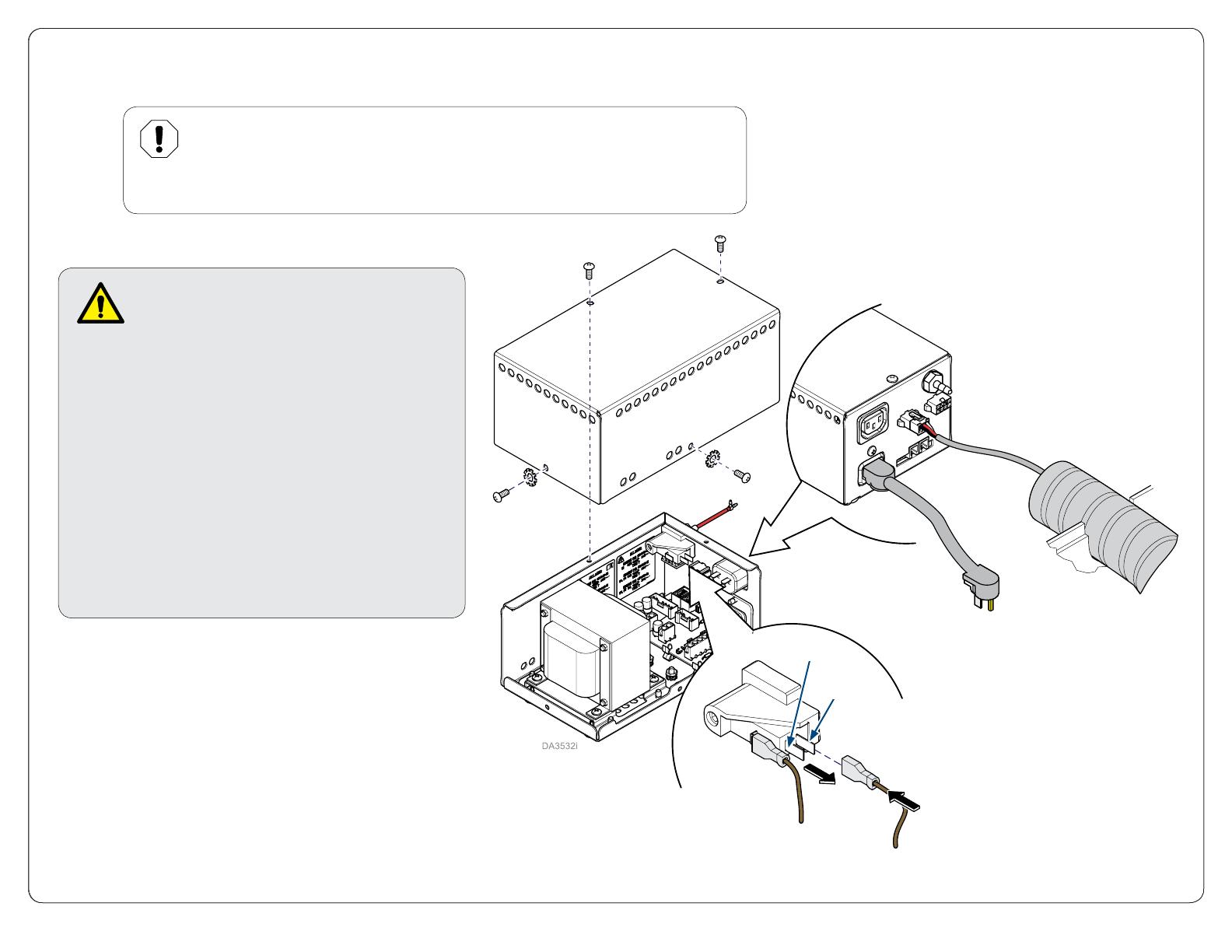
To Bypass the Air Pressure Switch...
A) Disconnect power.
B) Remove screws, lock washers and cover.
C) Disconnect brown wire from the NO terminal on
the air pressure switch.
D) Connect brown wire to the NC terminal on the air
pressure switch.
E) Install cover and secure with screws and lock
washers.
F) Reconnect power to the power supply.
003-2572-00
midmark.com
English-5
Style G
© 2011 Midmark Corp. | 60 Vista Drive Versailles, OH 45380 USA | 1-800-643-6275 | 1-937-526-3662 |
Tension Adjustments
To adjust Flex Arm tension...
A) Remove end cap and top cover as shown.
B) Loosen or tighten adjustment nut as desired.
To adjust tension at Arm / Yoke pivot joints...
A) Remove neck cover as shown (see Note).
B) Loosen or tighten appropriate screws to adjust tension.
Note: Some halogen models have a short neck on the lighthead. It is not
necessary to remove the neck cover on these models.
To adjust tension at Light pivot joint...
A) Remove screw cover as shown.
B) Loosen set screw.
C) Loosen or tighten light pivot adjustment screw.
D) Tighten set screw.
Short Neck
Yoke Pivot
Adjustment Screw
Arm Pivot
Adjustment Screw
Adjustment Nut
Yoke Pivot
Adjustment Screws
Arm Pivot
Adjustment Screws
Light Pivot
Adjustment Screw
Set Screw
Neck Cover
(Long Neck)
003-2572-00
midmark.com
  • Page 1 1
  • Page 2 2
  • Page 3 3
  • Page 4 4
  • Page 5 5

Midmark Dental Light (Halogen) Installation guide

Type
Installation guide
This manual is also suitable for

Ask a question and I''ll find the answer in the document

Finding information in a document is now easier with AI