Page is loading ...

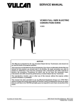
EV36S with Hot Top and French Plates Shown
EV Series Electric Ranges
MODELS
EV12
EV24S
EV36S
EV48S
EV48SS
EV60SS
EV72SS
- NOTICE -
This Manual is prepared for the use of trained Hobart Service Technicians and should not
be used by those not properly qualified.
This manual is not intended to be all encompassing. If you have not attended a Hobart Service
School for this product, you should read, in its entirety, the repair procedure you wish to
perform to determine if you have the necessary tools, instruments and skills required to
perform the procedure. Procedures for which you do not have the necessary tools,
instruments and skills should be performed by a trained Hobart Service Technician.
The reproduction, transfer, sale or other use of this manual, without the express written
consent of Hobart, is prohibited.
This manual has been provided to you by ITW Food Equipment Group LLC ("ITW FEG")
without charge and remains the property of ITW FEG, and by accepting this manual you agree
that you will return it to ITW FEG promptly upon its request for such return at any time in the
future.
SERVICE MANUAL
A product of Vulcan-Hart 3600 North Point Blvd Baltimore, MD 21222
F45586 Rev. A (1122)

TABLE OF CONTENTS
SERVICE UPDATES ....................................................................................... 4
SERVICE UPDATES ................................................................................... 4
TIS DOCUMENT LIST - EV SERIES ELECTRIC RANGES ............................................... 4
GENERAL .................................................................................................. 5
INTRODUCTION ....................................................................................... 5
INSTALLATION, OPERATION AND MAINTENANCE .................................................... 5
MODEL CONFIGURATIONS ............................................................................ 5
SPECIFICATIONS ...................................................................................... 5
TOOLS ................................................................................................. 6
SERVICE PROCEDURES AND ADJUSTMENTS ............................................................ 8
OVEN THERMOSTAT CALIBRATION ................................................................... 8
GRIDDLE THERMOSTAT CALIBRATION ............................................................... 8
HOT TOP THERMOSTAT CALIBRATION ............................................................... 9
INFINITE SWITCH TEST (208V/240V) ................................................................. 10
3 HEAT SWITCH TEST (480V) ........................................................................ 10
HEATING ELEMENT TEST ............................................................................ 11
REMOVAL AND REPLACEMENT OF PARTS .............................................................. 13
FRONT CONTROL PANEL ............................................................................ 13
OVEN CONTROL PANEL ............................................................................. 13
KICK PANEL .......................................................................................... 14
RANGE TOPS ........................................................................................ 14
OVEN DOOR ......................................................................................... 15
OVEN HEATING ELEMENTS .......................................................................... 16
TOP ELEMENT ................................................................................... 16
BOTTOM ELEMENT .............................................................................. 16
FRENCH PLATE ...................................................................................... 17
HOT TOP ............................................................................................. 18
GRIDDLE HEATING ELEMENT ....................................................................... 18
OVEN THERMOSTAT ................................................................................. 19
GRIDDLE AND HOT TOP THERMOSTATS ............................................................ 20
3 HEAT SWITCH / INFINITE SWITCH ................................................................. 21
INDICATOR LIGHTS .................................................................................. 22
ELECTRICAL OPERATION ................................................................................ 23
COMPONENT FUNCTION ............................................................................ 23
COMPONENT LOCATION ............................................................................. 23
STANDARD OVEN SEQUENCE OF OPERATION ..................................................... 24
208/240V ......................................................................................... 24
480V .............................................................................................. 24
WIRING DIAGRAMS ...................................................................................... 25
EV12 RANGE TOP - 208V & 240V ..................................................................... 25
EV12 RANGE TOP - 480V ............................................................................. 26
EV24 RANGE TOPS - 208V & 240V ................................................................... 27
EV24 STANDARD OVEN - 208V & 240V ............................................................... 28
EV36 & EV60 RANGE TOPS - 208V & 240V ........................................................... 29
EV36 & EV60 STANDARD OVEN - 208V & 240V ....................................................... 30
EV24 RANGE TOPS - 480V ........................................................................... 31
EV24 STANDARD OVEN - 480V ....................................................................... 32
EV36 RANGE TOPS - 480V ........................................................................... 33
EV36 STANDARD OVEN - 480V ....................................................................... 34
TROUBLESHOOTING ..................................................................................... 35
TROUBLESHOOTING - STANDARD OVEN ........................................................... 35
EV Series Electric Ranges
F45586 Rev. A (1122) Page 2 of 35


SERVICE UPDATES
SERVICE UPDATES
November 2022
• Updated OVEN THERMOSTAT CALIBRATION.
November, 2018
• Added TIS Document List.
TIS DOCUMENT LIST - EV SERIES ELECTRIC RANGES
SERVICE TAB
Document Title Document Type
EV Series Electric Restaurant Ranges Service Manual Service Manual
SERVICE TAB (Multimedia)
Document Title Document Type
Repair Flood-Damaged Equipment Misc
EV Series Electric Restaurant Ranges Operator
EV Series Ranges W/Griddle Elements Technical Service Bulletin (TSB)
EV Series with French Plates Replacement 18 Ga. French Plate Wiring Technical Service Bulletin (TSB)
Rating Plate Locations on Current Vulcan-Hart/Wolf Range Equipment Technical Service Bulletin (TSB)
SB 1023 EV Series Ranges with French Plates Technical Service Bulletin (TSB)
TSB 1037A Hobart to Vulcan "Common" Model Cross Reference List Technical Service Bulletin (TSB)
PARTS TAB
Document Title Document Type
EV Series Electric Restaurant Ranges Parts Catalog Parts Catalog
EV Series Electric Ranges - SERVICE UPDATES
F45586 Rev. A (1122) Page 4 of 35

GENERAL
INTRODUCTION
This manual is for the Vulcan EV Series Electric Restaurant Ranges. Procedures in this manual will apply to all
models unless specified. Pictures and illustrations will be of model EV36S with one French Plate and one 24" Griddle
section unless otherwise noted.
All of the information, illustrations and specifications contained in this manual are based on the latest product
information available at the time of printing.
INSTALLATION, OPERATION AND MAINTENANCE
For detailed installation, operation and cleaning instructions, refer to F38251 Installation & Operation manual sent
with each unit. The manual is also available online at www.vulcanequipment.com.
MODEL CONFIGURATIONS
The EV electric ranges come with a standard oven (S) and are available in several different range top configurations
such as: French Plates, Griddles or Hot Tops. A second (S) in the model number indicates an additional range with
a standard oven in the configuration (double oven).
• EV12 - 12" wide range section that provides additional range top heating selections of 2 French Plates or 1
Hot Top.
• EV24S - 24" wide electric range with available range top selections.
• EV36S - 36" wide electric range with available range top selections.
• EV48SS - 48" wide electric range, two combined 24" ranges with available range top selections.
• EV60SS - 60" wide electric range, two combined 24" and 36" ranges with available range top selections.
• EV72SS - 72" wide electric range, two combined 36" ranges with available range top selections.
SPECIFICATIONS
AVAILABLE VOLTAGES - 208 OR 240 VOLT - 1 OR 3-PHASE, 480 VOLT - 3-PHASE
Model
Configuration
Nominal AMPS Per Line Wire
3-Phase 1-Phase
208V 240V 480V
X Y Z X Y Z X Y Z 208V 240V
12" Range
EV12-2FP 9.6 17.0 9.6 8.3 14.0 8.3 4.2 7.2 4.2 19.0 17.0
EV12-1HT --- --- --- --- --- --- --- --- --- 24.0 21.0
EV Series Electric Ranges - GENERAL
Page 5 of 35 F45586 Rev. A (1122)

AVAILABLE VOLTAGES - 208 OR 240 VOLT - 1 OR 3-PHASE, 480 VOLT - 3-PHASE
Model
Configuration
Nominal AMPS Per Line Wire
3-Phase 1-Phase
208V 240V 480V
X Y Z X Y Z X Y Z 208V 240V
24" Range, Std
Oven
EV24S-4FP 37.5 37.5 33.3 32.5 32.5 28.9 16.3 16.3 14.4 62.5 54.2
EV24S-2HT 41.6 41.6 41.6 36.1 36.1 36.1 18.1 18.1 18.1 72.1 62.5
36" Range, Std
Oven
EV36S-6FP 37.5 50.0 54.1 32.5 43.3 46.9 16.3 21.7 23.5 81.7 70.8
EV36S-3HT 41.6 62.5 62.5 36.1 54.1 54.1 18.1 27.1 27.1 96.2 83.3
EV36S-2HT2FP 37.5 58.3 62.5 32.5 50.5 54.1 16.3 25.3 27.1 91.4 79.2
EV36S-1HT4FP 37.5 54.1 58.3 32.5 46.9 50.5 16.3 23.5 25.3 86.5 75.0
EV36S-2FP24G 35.0 45.0 51.6 30.3 39.0 44.7 15.2 19.5 22.4 76.0 65.8
EV36S-1HT24G 35.0 49.1 55.8 30.3 42.6 48.4 15.2 21.3 24.2 80.8 70.0
EV36S-4FP12G 35.0 47.5 54.1 30.3 41.1 46.9 15.2 20.6 23.3 78.8 68.3
EV36S-2HT12G 35.0 55.8 62.5 30.3 48.4 54.1 15.2 24.2 27.1 88.5 76.7
EV36S-36G 35.0 42.5 49.1 30.3 36.8 42.6 15.2 18.4 21.3 73.1 63.3
NOTE:
1. FP = French Plate (2 per 12" section); HT = Hot Top (1 per 12" section); G = Griddle (12", 24" or 36" wide); and
S = Standard oven. Additional information on the wiring configurations, kilowatts and amperage values can be found
under WIRING DIAGRAMS.
2. Ranges are factory wired for 3-phase service but are field convertible to 1-phase. Refer to the wiring diagrams
in this manual or schematic decals attached to the range for the necessary wiring changes.
3. All ranges over 36" wide will have two separate electrical connections.
TOOLS
Standard
• Standard set of hand tools.
• VOM with minimum of NFPA-70E CATIII 600V, UL/CSA/TUV listed. Sensitivity of at least 20,000 ohms per
volt and the ability to measure DC micro amps. Meter leads must also be rated at CAT III 600V.
EV Series Electric Ranges - GENERAL
F45586 Rev. A (1122) Page 6 of 35

Special
• Temperature tester (thermocouple type) with surface mount probe.
• Clamp on type amp meter with minimum of NFPA-70E CAT III 600V, UL/CSA/TUV listed.
• Two standard 1/4"- 20 x 1" bolts (allen head recommended). The bolts are used to relieve spring tension on
the door hinge during door removal and installation.
• Loctite® 246™ for door handle screws.
• A non-permanent type sealer (preferably fast drying) such as nail polish or equivalent for sealing thermostat
adjustment screw. If using Loctite® 242™, it begins to set in approximately 10 minutes and fully cures in 24
hours according to manufacturer.
EV Series Electric Ranges - GENERAL
Page 7 of 35 F45586 Rev. A (1122)

SERVICE PROCEDURES AND ADJUSTMENTS
OVEN THERMOSTAT
CALIBRATION
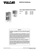
1. Place a temperature tester probe in the
geometric center of the oven.
2. Set the infinite switch (1, Fig. 1) for the top oven
element to OFF during oven thermostat
calibration.
3. Set the thermostat (2, Fig. 1) to 350°F.
4. Allow the thermostat to cycle three times.
5. Note the tester reading when the oven indicator
light (3, Fig. 1) turns ON and OFF.
Fig. 1
6. Add these two temperatures together, then
divide the sum by 2 to obtain an average
temperature.
A. If the average temperature is within 25°F of
the set temperature, the thermostat is
calibrated.
B. If the average temperature is not within 25°F
of the set temperature:
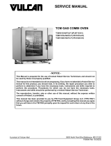
1) Remove thermostat knob. Maintain
thermostat setting during removal.
2) Hold thermostat stem to prevent
movement. Insert a flathead
screwdriver into thermostat stem (1,
Fig. 2) until it reaches the calibration
screw.
Fig. 2
3) Turn adjustment screw
counterclockwise to increase and
clockwise to decrease temperature.
NOTE: A 1/4 turn equals 35°F change.
7. Replace knob and repeat steps 4 to 6 until
average temperature is within 25°F of set
temperature.
8. Reseal adjustment screw to prevent movement.
9. If thermostat cannot be calibrated, replace
thermostat as outlined under OVEN
THERMOSTAT.
GRIDDLE THERMOSTAT
CALIBRATION
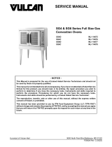
1. Clean temperature test area on griddle surface
then place temperature tester surface mount
probe at that location. See table for proper testing
locations according to griddle size.
NOTE: This procedure will need to be performed for
each testing location on the 24" and 36" griddles.
Griddle Size Distance(s) From Left
Edge of Griddle
12" 6"
24" 6", 18"
36" 6", 18", 30"
NOTE: All readings taken 12" from front of griddle.
2. Set thermostat to a temperature above 300°F.
3. Allow thermostat to cycle three times.
EV Series Electric Ranges - SERVICE PROCEDURES AND ADJUSTMENTS
F45586 Rev. A (1122) Page 8 of 35

4. Note tester reading when the indicator light turns
ON and OFF.
5. Add these two temperatures together then divide
the sum by 2 to obtain an average temperature.
A. If the average temperature is within 25°F of
the set temperature, the thermostat is
calibrated.
B. If the average temperature is not within 25°F
of the set temperature:
1) Remove thermostat knob. Maintain
thermostat setting during removal.
2) Hold thermostat stem to prevent
movement. Insert a flathead
screwdriver into thermostat stem until
it reaches the calibration screw.
Fig. 3
3) Turn adjustment screw clockwise to
increase and counterclockwise to
decrease temperature.
NOTE: A 1/4 turn equals 35°F change.
6. Replace knob and repeat steps 3 to 5 until
average temperature is within 25°F of set
temperature.
7. Reseal adjustment screw to prevent movement.
8. If thermostat cannot be calibrated, replace
thermostat as outlined under GRIDDLE AND
HOT TOP THERMOSTATS .
HOT TOP THERMOSTAT
CALIBRATION
1. Clean temperature test area surface in the center
of the Hot Top then place temperature tester
surface mount probe at that location.
2. Set thermostat to 350°F.
NOTE: The equivalent on the numbered dial is
approximately 5.
3. Allow the thermostat to cycle three times.
4. Note the tester reading when the indicator light
turns ON and OFF.
5. Add these two temperatures together, then
divide the sum by 2 to obtain an average
temperature.
A. If the average temperature is within 25°F of
the set temperature, the thermostat is
calibrated.
B. If the average temperature is not within 25°F
of the set temperature:
1) Remove thermostat knob. Maintain
thermostat setting during removal.
2) Hold thermostat stem to prevent
movement. Insert a flathead
screwdriver into thermostat dial stem
until it reaches the calibration screw.
Fig. 4
3) Turn adjustment screw clockwise to
increase and counterclockwise to
decrease temperature.
NOTE: A 1/4 turn equals 35°F change.
EV Series Electric Ranges - SERVICE PROCEDURES AND ADJUSTMENTS
Page 9 of 35 F45586 Rev. A (1122)

6. Replace knob and repeat steps 3 to 5 until
average temperature is within 25°F of set
temperature.
7. Reseal adjustment screw to prevent movement.
8. If thermostat cannot be calibrated, replace
thermostat as outlined under GRIDDLE AND
HOT TOP THERMOSTATS.
INFINITE SWITCH TEST (208V/
240V)
Certain procedures in this section
require electrical test or
measurements while power is
applied to the machine. Exercise
extreme caution at all times and
follow Arc Flash procedures. If test
points are not easily accessible,
disconnect power and follow
Lockout/Tagout procedures, attach
test equipment and reapply power to
test.
NOTE: Refer to AI4007 in WIRING DIAGRAMS for
switch terminal locations.
1. Lower the FRONT CONTROL PANEL to access
infinite switch for a French Plate.
A. If checking infinite switch for the oven,
remove OVEN CONTROL PANEL.
2. Connect a voltmeter to the output terminals H1
and H2.
3. Reconnect power to machine.
4. Turn knob to the desired setting.
5. Compare the percentage of ON time to OFF time.
NOTE: ±7.5% tolerance allowable.
Knob
Setting % on Time Seconds
on
Seconds
off
Hi 100 ALL 0
Med. 48 15 15
Low 37 8 14
Knob
Setting % on Time Seconds
on
Seconds
off
Med. Low 28 7 24
Very Low 7 3 33
6. If the percentage is not correct, replace the
switch as outlined under 3 HEAT SWITCH /
INFINITE SWITCH.
3 HEAT SWITCH TEST (480V)
Certain procedures in this section
require electrical test or
measurements while power is
applied to the machine. Exercise
extreme caution at all times and
follow Arc Flash procedures. If test
points are not easily accessible,
disconnect power and follow
Lockout/Tagout procedures, attach
test equipment and reapply power to
test.
NOTE: Refer to AI4008 in WIRING DIAGRAMS for
switch terminal locations.
1. Lower the FRONT CONTROL PANEL to access
3 heat switch for a French Plate.
2. Reconnect power to machine.
3. Check input voltage at L3 and L2 on the switch
terminals.
4. Check for the correct output voltage at the output
terminals for all knob settings of the switch.
Knob Settings
L3 Input -
Output at
Terminal(s)
L2 Input -
Output at
Terminal(s)
High 1 & 3 2
Med 1 2
Low 1 3
5. If the voltages are not correct, replace the switch
as outlined under 3 HEAT SWITCH / INFINITE
SWITCH.
EV Series Electric Ranges - SERVICE PROCEDURES AND ADJUSTMENTS
F45586 Rev. A (1122) Page 10 of 35

HEATING ELEMENT TEST
Certain procedures in this section require electrical test or measurements while power is
applied to the machine. Exercise extreme caution at all times and follow Arc Flash procedures.
If test points are not easily accessible, disconnect power and follow Lockout/Tagout
procedures, attach test equipment and reapply power to test.
NOTE: 208/240V - The standard oven uses and infinite switch to control the top element for browning and a
thermostat to control the bottom element for oven heating. The thermostat supplies power to the infinite switch and
must be ON for the top element to heat.
NOTE: 480V only - The standard oven uses a single thermostat to control the top element for browning and the
bottom element for oven heating.
1. Set temperature control to the highest setting for the heating element to test:
A. Standard oven - top and bottom elements.
B. Hot Top element.
C. French Plate element.
D. Griddle element.
2. Measure voltage at the heating element terminals and verify it against data plate voltage.
A. If voltage is incorrect, see TROUBLESHOOTING to help determine the possible cause. If voltage is
correct, check current draw (amps) through the heating element lead wires.
NOTE: Checking current draw is preferred over a resistance check when a clamp on type amp meter is
available.
B. If current draw is correct then heating element is functioning properly. See HEATING ELEMENT
TABLE for proper values. If current draw is not correct, turn temperature control OFF and disconnect the
electrical supply to the range. On ranges with two ovens, each section will have its own supply power
connection.
C. Replace heating element for the range as outlined under the appropriate procedure listed below then
proceed to step 3:
1) OVEN HEATING ELEMENTS
2) HOT TOP
3) FRENCH PLATE
4) GRIDDLE HEATING ELEMENT
D. If unable to check current draw, a resistance check may indicate a malfunctioning element.
1) Disconnect electrical supply to the range. On ranges with two ovens, each section will have its own
supply power connection.
2) Remove lead wires from the heating element and check resistance (ohms). See HEATING
ELEMENT TABLE for proper values.
E. If resistance is not correct, replace heating element for the range as outlined under the appropriate
procedure listed in step 2C.
3. Check for proper operation.
EV Series Electric Ranges - SERVICE PROCEDURES AND ADJUSTMENTS
Page 11 of 35 F45586 Rev. A (1122)

HEATING ELEMENT TABLE
Voltage Element KW per Element AMPS per Element
Lead OHMS per Element
208
Standard Oven (Top) 1.25 6.0 34.6
Standard Oven (Bottom) 3.75 18.0 11.5
Hot Top 5.00 24.0 8.7
French Plate 2.00 9.6 21.6
Griddle 3.40 16.3 12.7
240
Standard Oven (Top) 1.25 5.2 46.1
Standard Oven (Bottom) 3.75 15.6 15.4
Hot Top 5.00 20.8 11.5
French Plate 2.00 8.3 28.8
Griddle 3.40 14.2 16.9
480
Standard Oven (Top) 1.25 2.6 184.3
Standard Oven (Bottom) 3.75 7.8 61.4
Hot Top 5.00 10.4 46.1
French Plate 2.00 4.2 115.2
Griddle 3.40 7.1 67.8
NOTE:
1. Values in the table are nominal. Tolerance is +5/-10%.
2. Voltage values are @ 60Hz.
3. Resistance values (ohms) are @ 77° F.
EV Series Electric Ranges - SERVICE PROCEDURES AND ADJUSTMENTS
F45586 Rev. A (1122) Page 12 of 35

REMOVAL AND REPLACEMENT OF PARTS
FRONT CONTROL PANEL
Disconnect the electrical power to
the machine and follow lockout /
tagout procedures.
1. Pull out grease tray (1, Fig. 5) on models with
griddle.
2. Remove 4 screws (2, Fig. 5) from control panel.
NOTE: Control panel is hinged and will rotate down.
Fig. 5
3. Reverse procedure to install.
OVEN CONTROL PANEL
Disconnect the electrical power to
the machine and follow lockout /
tagout procedures.
1. Remove plug from the access hole in the oven
control panel.
Fig. 6
2. Remove screw securing oven control panel to
frame.
3. Pull the oven control panel outward at the top and
lift to remove from frame.
4. Note wire locations and disconnect from the
infinite switch (1, Fig. 7) thermostat (2, Fig. 7) and
oven light (3, Fig. 7).
Fig. 7
5. Reverse procedure to install.
EV Series Electric Ranges - REMOVAL AND REPLACEMENT OF PARTS
Page 13 of 35 F45586 Rev. A (1122)

KICK PANEL
Disconnect the electrical power to
the machine and follow lockout /
tagout procedures.
1. Lift kick panel to disengage from the mounting
bracket upper pin and allow panel to rotate down.
Fig. 8
2. Apply outward pressure on one of the panel
mounting ends to disengage from mounting
bracket lower pin.
3. Reverse procedure to install.
RANGE TOPS
Disconnect the electrical power to
the machine and follow lockout /
tagout procedures.
1. Remove screws (2, Fig. 9) securing backsplash
(1,Fig. 9) to frame.
Fig. 9
2. Lift backsplash to disengage the support tabs
from mounting slots in frame. Place backsplash
to the side until ready to install.
3. Open FRONT CONTROL PANEL.
4. Remove range top as described below:
Fig. 10
A. French Plate (1, Fig. 10) - Remove screws
securing French Plate (Fig. 11) to frame.
B. Hot Top (2, Fig. 10) - Remove screws
securing bull nose (1, Fig. 12) to frame then
lift bull nose off range.
C. Griddle (3, Fig. 10) - Remove screws
securing bull nose (1, Fig. 12) to frame then
lift bull nose off range.
Fig. 11
Fig. 12
EV Series Electric Ranges - REMOVAL AND REPLACEMENT OF PARTS
F45586 Rev. A (1122) Page 14 of 35

NOTE: On Hot Tops and griddles, the number of
screws securing bull nose to frame depends on bull
nose length.
5. Lift the range top being removed and position it
to access the electrical connections.
6. Disconnect the electrical connections.
7. Reverse procedure to install.
8. Check range top for proper operation.
OVEN DOOR
Removal
1. Remove OVEN CONTROL PANEL.
NOTE: Removal of the oven control panel is to
provide additional space on the right side of door to
ease door removal and installation.
2. Lower KICK PANEL.
3. Fully open the oven door.
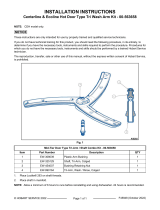
NOTE: Refer to Fig. 13 and the description table
below to identify components.
4. Insert a 1/4"-20 x 1" long bolt (as listed under
TOOLS) into each door hinge slot at the top of
the spring loaded hinge.
Fig. 13
Item Description
1 Bolt
2 Door
3 Swivel Hinge
4 Spring-Loaded Hinge
5 Bottom Edge of Door Hinge Stop
Item Description
6 Door Hinge Stop
7 Bar
5. Close door until it's close to the front control
panel. As the door approaches this position, you
should notice a decrease in the spring tension on
the door.
6. Remove door as follows:
A. Hold door at bottom corners then lift the door
up and out to disengage the swivel hinge
and spring-loaded hinge.
B. The notch on swivel hinge must release
from bottom edge of the door hinge stop to
remove door. As needed, lift up on the
swivel hinges using forefinger to aid in
releasing.
C. The spring-loaded hinge must release from
the roller inside the slot on door hinge stop
to remove door.
7. If replacing door or spring-loaded hinge, position
the door face down. Press down on hinge enough
to relieve spring force then remove bolt from door
hinge slot.
Installation
1. Compress each spring-loaded hinge enough to
insert the bolt into the slot at top of hinge.
2. Hold door at bottom corners while facing the oven
cavity. Place knee on the front of door to help
balance it as necessary during installation.
A. Using index fingers, lift swivel hinges until
they touch the spring-loaded hinges and
hold in place.
B. Tilt the top of door toward the oven so that
the swivel hinge is at a slightly downward
angle to pass between the bar and bottom
edge of door hinge stop.
C. Insert door hinges into the slots making sure
that the spring-loaded hinges go above the
bar to catch on the roller and the swivel
hinges go underneath the bar to catch on
the bottom edge of door hinge slot.
D. Lower the door and position it as necessary
to engage the swivel hinge slots with the
bottom edge of both door hinge slots. Refer
to Fig. 15 below.
EV Series Electric Ranges - REMOVAL AND REPLACEMENT OF PARTS
Page 15 of 35 F45586 Rev. A (1122)

Fig. 15
3. Fully open door to check operation. If bottom
edge of door rubs the front edge of cavity bottom,
then the swivel hinge is not engaged as
described.
A. To seat the swivel hinge, open door
approximately 30° and pull in the same
direction on the door handle. The hinge
should drop into place.
4. Open door and check operation. If okay, remove
bolts and close door. If not okay, remove door
and repeat installation procedure.
5. Reinstall oven control panel.
6. Raise kick panel.
OVEN HEATING ELEMENTS
Disconnect the electrical power to
the machine and follow lockout /
tagout procedures.
Top Element
NOTE: If the rear of range is accessible, remove rear
flue panel to access the top heating element terminals
and disconnect lead wires. Otherwise, access is
available through the oven cavity as outlined in
procedure.
1. Remove oven racks.
2. Loosen element mounting brackets (1, Fig. 16).
3. Remove element mounting screws (2, Fig. 16).
Fig. 16
4. Remove element from brackets.
NOTE: Some brackets may need to be removed if
turning them will not completely free the element.
5. If removing element through oven cavity,
disconnect lead wires from heating element
terminals.
6. Remove element from oven cavity.
7. Reverse procedure to install.
NOTE: Do not force element into holding brackets.
8. Check range for proper operation.
Bottom Element
NOTE: The bottom heating element terminals can
only be accessed from the rear of the range.
1. Remove the rear flue panel (1, Fig. 17).
2. Remove element cover (2, Fig. 17).
Fig. 17
3. Disconnect lead wires from element terminals (1,
Fig. 18).
EV Series Electric Ranges - REMOVAL AND REPLACEMENT OF PARTS
F45586 Rev. A (1122) Page 16 of 35

Fig. 18
4. Remove oven racks.
5. Remove oven bottom.
6. Loosen element mounting brackets (1, Fig. 19).
7. Remove element mounting screws (2, Fig. 19).
Fig. 19
8. Remove bottom element from mounting brackets
and lift out of the oven cavity.
9. Reverse procedure to install.
NOTE: Work mounting brackets around until element
is secured without force.
10. Check range for proper operation.
FRENCH PLATE
Disconnect the electrical power to
the machine and follow lockout /
tagout procedures.
1. Remove RANGE TOPS.
2. Remove electrical connections noting their
locations (1, Fig. 20).
Fig. 20
3. Support the French Plate (1, Fig. 21).
A. Remove the nut, spring washer, and locking
bracket (2, 3, 4 Fig. 21).
Fig. 21
4. Remove French Plate from range top.
5. Reverse procedure to install.
6. Check range for proper operation.
EV Series Electric Ranges - REMOVAL AND REPLACEMENT OF PARTS
Page 17 of 35 F45586 Rev. A (1122)

HOT TOP
Disconnect the electrical power to
the machine and follow lockout /
tagout procedures.
1. Remove RANGE TOPS.
2. Remove mounting nuts (1, Fig. 22) that hold
thermostat bulb clamp (2, Fig. 22) to the plate
assembly.
Fig. 22
3. Remove thermostat bulb clamp and thermostat
bulb from Hot Top.
4. Remove the inside terminal screws (1, Fig. 23)
from electrical connections.
Fig. 23
5. Bend hooks inward slightly (1, Fig. 24) then
remove electrical connections.
Fig. 24
6. Remove Hot Top.
7. Reverse procedure to install.
8. Check range for proper operation.
GRIDDLE HEATING ELEMENT
Disconnect the electrical power to
the machine and follow lockout /
tagout procedures.
NOTE: 24" wide griddle shown.
1. Remove RANGE TOPS.
2. Remove thermostat bulb from the angle iron
weldment (1, Fig. 25) on the bottom of griddle
plate.
3. Disconnect element wiring from heating element
terminals (2, Fig. 25).
Fig. 25
EV Series Electric Ranges - REMOVAL AND REPLACEMENT OF PARTS
F45586 Rev. A (1122) Page 18 of 35

4. Remove mounting nuts (3, Fig. 25) securing
griddle element cover to griddle plate.
5. Remove griddle element cover from griddle
plate.
6. Remove mounting nuts (1, Fig. 26) securing the
griddle element clamp (2, Fig. 26).
Fig. 26
7. Remove griddle element clamp (2, Fig. 26) from
the element and griddle plate.
8. Remove griddle element from griddle plate.
9. Reverse procedure to install.
A. Position the element clamp with the
downward bend along the sides of the
clamp toward the griddle plate.
B. Torque the griddle element clamp mounting
nuts to 30 to 35 inch-pounds.
NOTE: A torque wrench is the preferred method for
tightening the griddle element clamp mounting nuts.
However, if a torque wrench is not available, tighten
all griddle element clamp mounting nuts finger tight,
then 1/2 additional turn with a wrench.
10. Check range for proper operation.
OVEN THERMOSTAT
Disconnect the electrical power to
the machine and follow lockout /
tagout procedures.
1. Remove thermostat knob.
2. Remove thermostat mounting screws.
Fig. 27
3. Remove OVEN CONTROL PANEL.
4. Disconnect lead wires from thermostat noting
their locations.
Fig. 28
5. Remove thermostat bulb from the oven cavity
mounting clips.
A. Pull capillary tube and thermostat bulb
through the opening in sidewall of the oven
cavity.
EV Series Electric Ranges - REMOVAL AND REPLACEMENT OF PARTS
Page 19 of 35 F45586 Rev. A (1122)

Fig. 29
6. Remove thermostat from oven.
7. Reverse procedure to install.
When installing, do not bend and kink capillary tube or
damage to the control may occur.
8. Perform OVEN THERMOSTAT CALIBRATION.
9. Check range for proper operation.
GRIDDLE AND HOT TOP
THERMOSTATS
Disconnect the electrical power to
the machine and follow lockout /
tagout procedures.
1. Remove thermostat knob.
2. Remove thermostat mounting screws.
Fig. 30
3. Open FRONT CONTROL PANEL.
4. Disconnect lead wires from thermostat noting
their locations.
Fig. 31
5. Access the underside of RANGE TOPS. The
picture below shows the thermostat bulb and
clamp for a Hot Top.
A. To access the thermostat bulb and clamp for
a griddle, refer to GRIDDLE HEATING
ELEMENT.
6. Remove mounting nuts (1, Fig. 32) from
thermostat bulb clamp (2, Fig. 32).
EV Series Electric Ranges - REMOVAL AND REPLACEMENT OF PARTS
F45586 Rev. A (1122) Page 20 of 35
/