Page is loading ...

TCM GAS COMBI OVEN
TCM-61G-NAT/LP (VPJ071G-81)
TCM-101G-NAT/LP (VPJ101G-81)
TCM-102G-NAT/LP (VPJ102G-81)
- NOTICE -
This Manual is prepared for the use of trained Hobart Service Technicians and should not
be used by those not properly qualified.
This manual is not intended to be all encompassing. If you have not attended a Hobart Service
School for this product, you should read, in its entirety, the repair procedure you wish to
perform to determine if you have the necessary tools, instruments and skills required to
perform the procedure. Procedures for which you do not have the necessary tools,
instruments and skills should be performed by a trained Hobart Service Technician.
The reproduction, transfer, sale or other use of this manual, without the express written
consent of Hobart, is prohibited.
This manual has been provided to you by ITW Food Equipment Group LLC ("ITW FEG")
without charge and remains the property of ITW FEG, and by accepting this manual you agree
that you will return it to ITW FEG promptly upon its request for such return at any time in the
future.
SERVICE MANUAL
A product of Vulcan-Hart 3600 North Point Blvd Baltimore, MD 21222
F45909 Rev. B (0523)

TABLE OF CONTENTS
SERVICE UPDATES ....................................................................................... 4
SERVICE UPDATES ................................................................................... 4
GENERAL .................................................................................................. 5
INTRODUCTION ....................................................................................... 5
TOOLS ................................................................................................. 7
WATER QUALITY STATEMENT ........................................................................ 8
STAINLESS STEEL STATEMENT ...................................................................... 9
SPECIFICATIONS ...................................................................................... 9
REMOVAL AND REPLACEMENT OF PARTS .............................................................. 10
SIDE PANEL .......................................................................................... 10
BACK PANEL ......................................................................................... 10
DOOR PANEL ........................................................................................ 11
FRONT CONTROL PANEL ............................................................................ 11
STEAM AND WASH SOLENOID ASSEMBLY .......................................................... 11
FILTERED WATER PRESSURE RESTRICTOR ........................................................ 12
CONTROL PANEL BOARD ............................................................................ 12
ENCODER ............................................................................................ 14
BUZZER .............................................................................................. 15
HIGH LIMIT THERMOSTAT ........................................................................... 15
OUTPUT CONTROL ASSEMBLY ...................................................................... 16
OUTPUT CONTROL ASSEMBLY RELAY BOARD ..................................................... 19
FUSES ................................................................................................ 19
FAN .................................................................................................. 21
RECIRCULATING WASH PUMP CAPACITOR ......................................................... 22
DOOR ................................................................................................ 22
DOOR (LED STRIP) ................................................................................... 23
DOOR HANDLE AND LATCH ......................................................................... 24
DOOR CATCH ........................................................................................ 25
INTERNAL GLASS DOOR ............................................................................. 26
VENT MOTOR ........................................................................................ 26
FLOW METER ........................................................................................ 27
DETERGENT PUMP .................................................................................. 27
TEMPERATURE PROBE .............................................................................. 28
DESCALE / RINSE AID PUMP INTERNAL HOSE ...................................................... 28
DRAIN VALVE MOTOR ............................................................................... 29
CAVITY FAN MOTOR ................................................................................. 29
MOTOR SHAFT SEAL ................................................................................ 30
DOOR SEAL .......................................................................................... 30
COMBUSTION BLOWER .............................................................................. 31
GAS VALVE .......................................................................................... 31
GAS TRANSFORMER ................................................................................ 32
WIRING / FLUID DIAGRAMS .............................................................................. 33
DIAGRAMS ........................................................................................... 33
FLUID DIAGRAMS .................................................................................... 38
SERVICE PROCEDURES AND ADJUSTMENTS ........................................................... 40
CONVECTION MOTOR RESISTANCE ................................................................ 40
SOLENOID VALVES .................................................................................. 42
CHANGE TYPE OF GAS SUPPLY ..................................................................... 42
ORIFICE .............................................................................................. 45
ADJUST GAS VALVE ................................................................................. 47
ELECTRODES (GAS BURNER) ....................................................................... 49
GAS VALVE RESISTANCE ............................................................................ 50
TCM GAS COMBI OVEN
F45909 Rev. B (0523) Page 2 of 113

ELECTRICAL OPERATION ................................................................................ 51
GAS COMPONENTS .................................................................................. 51
COMPONENT FUNCTION ............................................................................ 52
OUTPUT CONTROL ASSEMBLY ...................................................................... 54
SOFTWARE .............................................................................................. 57
SOFTWARE VERSION HISTORY ..................................................................... 57
SOFTWARE UPDATE PROCEDURE .................................................................. 57
PROGRAMING ........................................................................................ 61
BOARDS .............................................................................................. 68
DISPLAY SCREEN CONTROLS AND INFORMATION ..................................................... 70
ACCESS MAINTENANCE SCREENS .................................................................. 70
AUTO SCREEN CONTROLS AND INFORMATION .................................................... 73
MANUAL SCREEN CONTROLS AND INFORMATION ................................................. 74
TOOL BOX SCREEN CONTROLS AND INFORMATION ............................................... 74
AUTO CLEANING SCREEN CONTROLS AND INFORMATION ........................................ 75
MANUAL CLEANING SCREEN CONTROLS AND INFORMATION ..................................... 76
USER MANUAL INFORMATION ....................................................................... 78
DATA EXCHANGE CONTROLS AND INFORMATION ................................................. 78
CLIENT PARAMETER SCREEN CONTROLS AND INFORMATION .................................... 80
INSTALLATION PARAMETERS SCREEN CONTROLS AND INFORMATION ........................... 83
TECHNICAL PARAMETERS SCREEN CONTROLS AND INFORMATION .............................. 84
WATER TREATMENT COUNTER ..................................................................... 88
DIAGNOSTICS ............................................................................................ 91
ERROR HISTORY / COUNTER SCREENS AND INFORMATION ....................................... 91
DIAGNOSTIC SCREENS .............................................................................. 92
TEMPERATURE PROBE TEST ....................................................................... 94
PT100 PROBE CHECK ................................................................................ 95
TROUBLESHOOTING ..................................................................................... 96
TROUBLESHOOTING ................................................................................. 96
ERROR CODES ...................................................................................... 97
TROUBLESHOOTING - GAS COMPONENTS ........................................................ 107
COMPONENT LOCATION ............................................................................... 111
TECHNICAL COMPONENTS ......................................................................... 111
TCM GAS COMBI OVEN
© VULCAN 2023
Page 3 of 113 F45909 Rev. B (0523)

SERVICE UPDATES
SERVICE UPDATES
May 2023
•Updated ACCESS MAINTENANCE SCREENS.
•Updated ERROR CODES.
•Updated TROUBLESHOOTING - GAS
COMPONENTS.
•Updated TECHNICAL COMPONENTS.
February 2023
•Updated TOOLS.
•Updated WATER QUALITY STATEMENT.
•Updated SPECIFICATIONS.
•Updated FILTERED WATER PRESSURE
RESTRICTOR.
•Updated CONTROL PANEL BOARD.
•Updated OUTPUT CONTROL ASSEMBLY .
•Updated GAS TRANSFORMER.
•Added diagrams in DIAGRAMS
•Updated CONVECTION MOTOR
RESISTANCE.
•Updated SOLENOID VALVES.
•Updated ORIFICE.
•Updated GAS COMPONENTS.
•Updated SOFTWARE VERSION HISTORY.
•Updated SOFTWARE UPDATE PROCEDURE.
•Updated PROGRAMING.
•Updated BOARDS.
•Updated TROUBLESHOOTING.
•Updated TROUBLESHOOTING - GAS
COMPONENTS.
TCM GAS COMBI OVEN - SERVICE UPDATES
F45909 Rev. B (0523) Page 4 of 113

GENERAL
INTRODUCTION
TCM GAS COMBI OVEN - GENERAL
Page 5 of 113 F45909 Rev. B (0523)
• Multiple cooking capabilities from one piece of equipment: Baking, Steaming, Roasting, Grilling, Air-Fry,
Rethermalization, Proofing, Finishing, Poaching, Stewing, Low Temp, Defrosting, Cook & Hold, and more.
• FastPAD® toughened glass control panel: comprising a large color LCD touch screen and coding turn/push
knob.
• Auto reverse fan, adjustable from 1 to 100%.
• Rapid product drying by opening the motorized vent, for a crispier exterior.
• Automatic adjustment of the oven power to suit the load being cooked, for results that are always to the precise
degree required.
• Automatically switches to energy saving mode after a period of inactivity (adjustable).
• Temperature with visual display of Set and Actual. User Interface including Manual displays for ABC, JET or
ECO operator functions. ABC automatically adjusts humidity after setting temperature. ABC and JET features
always on function, no start button to activate. JET for manual convection, steam and combi settings. ECO for
required start button activation providing maximum energy savings.
• Full Cleaning System»: Automatic cleaning.
COOKING MODES
• Convection from 32 to 480°F - Saturated steam: steam to 200°F.
• Combi from 85 to 480°F (with humidity adjustable from 0 to 99%) - Low temperature: steam from 85 to 207°F.
• High temperature steam: steam from 208 to 220 °F.
• Regeneration.
• Delta T.
AUTOMATIC COOKING MODE
• 80 preloaded recipes as standard with the option to adjust the degree of cooking and the coloration.
• It is possible to create entirely personalized recipes.
• Displayed as text or as pictures via the library within the oven.
• Recipes are classified by family and / or in « my recipes ».
SERVICE MODE
• Toolbox screen to access error logs and service diagnostics.
• Transfer recipes and photographs via a computer.
• Parameters can be modified to give maximum personalization.
• Visual Diagnostic System: interactive screen intended for technicians.

•FUNCTIONS
• Automatic oven cavity cooling, door closed: improved reactivity.
• Humidifier : provides instant steam (shot of vapor): ideal for bread.
• Hold function : temperature holding phase after cooking (semi static oven). Avoids the surface of the product
drying out.
• Automatic rinse possible between cooking operations.
• Timer: continuous up to 99:00 hours and minutes with set, remaining or count time displayed.
• Timer reloads for batch cooking after completion of timed cycle (ABC).
• Multi timer: cooking times can be programmed for each level : bringing greater flexibility during service.
• Flashing LED lights & audible alarm system alert user when cooking cycle finished.
EQUIPMENT
TCM GAS COMBI OVEN - GENERAL
F45909 Rev. B (0523) Page 6 of 113
• Cool touch athermic double glazed clipped door with left or right hand rotation of the handle to open, hinged
to the left and a simple push closure. Opens to 180° with hinged internal glass to make cleaning easier.
• Cavity illumination by a strip of LEDs in the door.
• Features electrical protection, a door safety and thermal overload protection.
STANDARD SUPPLY
• 1 set of side support runners and racks.
• Core probe socket allowing the use of a removable core probe.
• USB port.

TOOLS
Standard
• Standard set of hand tools.
• Metric set of hand tools.
• VOM with measuring micro amp current tester. Any VOM with minimum of CAT III 600V, CE certified. Sensitivity
of at least 20,000 ohms per volt can be used. Ability to measure uF microfarids. In addition, meter leads must
also be a minimum of CAT III 600V.
• Clamp on type amp meter with minimum of NFPA-70E CAT III 600V, UL/CSA/TUV listed.
• Temperature tester (thermocouple type).
• Field service grounding kit.
Special
• Gas combustion analyzer and manometer.
• Combustion analyzer Bacharach Fyrite Pro 125 Bacharach model# 24-8105 or Fyrite "Insight" Model
24-8251.
•Manometer U tube Part No. TL-84908 or equivalent.
• Set of jeweler's screwdrivers.
• Thumb drive.
• RECTORSEAL 5® or equivalent NSF rated thread sealant.
• Rod / Gauges
• Rod / gauge by 6mm diameter for electrode flame detection.
• Rod / gauge by 3mm and 4mm diameters for ignition electrodes.
• High Temperature Silicone.
• High Temperature Quality Grease.
• Hub Puller.
TCM GAS COMBI OVEN - GENERAL
Page 7 of 113 F45909 Rev. B (0523)

WATER QUALITY STATEMENT
The fact that a water supply is potable is no guarantee that it is suitable for steam generation. Proper water quality
can improve the taste of the food prepared in the oven, reduce scale build-up or corrosion, and extend equipment
life. Local water conditions vary from one location to another and can change throughout the year. The
recommended water treatment for effective and efficient use of this equipment will vary depending on the local
water conditions. Your water supply must be within the general guidelines outlined in the chart below at all times
during use of this machine or service issues not covered under warranty may result.
NOTE: Failure to properly maintain water quality or preventative procedures for water can lead to issues not
covered under warranty.
WATER SUPPLY GENERAL GUIDELINES CHART 1
Supply Pressure (dynamic flow) 30-60 psig
Hardness less than 3 grains (17.1 ppm = 1 grain of hardness)
Silica less than 13 ppm
Chloramines 2zero
Chlorides 2less than 30 ppm 3
Total Chlorine 4zero
PH range 7-8
Un-Dissolved Solids less than 5 microns
Drain Line Drain line pee trap must be installed at back of unit to
open gap floor sink.
1 Testing of water is always done AFTER water
filter or water treatment used. Water quality does
change with usage and should be checked
periodically to see if the condition worsens.
2 A carbon block filter system should always be
used to remove Chlorine and Chloramine. If a
water softener is used, a carbon block is still
required. Check with your local water treatment
specialist for proper sizing and replacement
intervals for the carbon block cartridge.
3 If the Chlorides exceed 30 ppm and the oven is
used more than 8 hours during the day in steam
or combination mode the cavity will require
rinsing every 8 hours. Failure to do so will result
in corrosion and rusting of the oven cavity and
interior parts. A Reverse Osmosis water treatment
system can be installed to eliminate chlorides
from the water and reduce the hardness.
Preventative washing and rinsing may be needed
more than once a day to prevent compounding of
contaminants inside cavity.
4 Total Chlorine of 4.0 ppm is the max limit for the
building water supply. A carbon block filter must
still be used to remove all Chlorine and
Chloramines from the water. Failure to do so will
result in corrosion and rust in the cooking cavity
which is not covered under warranty.
Water hardness should be treated by removing the
impurities (water softener with carbon block or
dechlorinator and/or in-line water treatment). Low
water hardness may also require a water treatment
system to reduce potential corrosion. Water treatment
has been shown to reduce costs associated with
machine cleaning, reduce deliming and reduce
corrosion of metallic surfaces.
Daily washing and rinsing of the cavity is required. In
some cases it may be needed more than once a day
to prevent compounding of contaminants deposited
inside cavity even with acceptable filtration. Failure to
wash and rinse down the cavity daily could result in
damage of the oven cavity and interior parts. A
Reverse Osmosis water treatment system can be
TCM GAS COMBI OVEN - GENERAL
F45909 Rev. B (0523) Page 8 of 113
installed to eliminate chlorides or other contaminates
from the water if needed.

STAINLESS STEEL STATEMENT
Stainless steel has a thin protective sheet formed on the metallic surface to protect it against corrosion. Anything
facilitating its partial destruction (food residues, overflow of liquids, stagnant liquids, etc.) reduces the resistance of
stainless steel to corrosion. While the composition of stainless steel enables it to withstand some chemical
aggression better than classical steels, it is not indestructible. Three main factors contributing to corrosion should
be watched for:
• Chemical environment.
• Temperature.
• Duration of contact.
The combination of these three factors may lead to the eventual destruction of parts of the equipment, even if they
have been made in very high-quality stainless steel. Generally, cleaning products, which are not appropriate or are
improperly used, lack of maintenance, or extreme conditions of use are often found to be the cause of damage.
SPECIFICATIONS
Electrical
Model Art Voltage kW Amps Natural Propane
VPJ071G TCM-61G-NAT/LP
120 0.4 3.3 55,959 54,253
208 0.4 1.9 55,959 54,253
240 0.4 1.7 55,959 54,253
VPJ101G TCM-101G-NAT/LP
120 0.4 3.3 93,151 90,080
208 0.4 1.9 93,151 90,080
240 0.4 1.7 93,151 90,080
VPJ102G TCM-102G-NAT/LP
120 0.6 5 155,594 150,810
208 0.6 2.9 155,594 150,810
240 0.6 2.5 155,594 150,810
Gas Pressure
Natural 6 - 10 WC
Propane 10 - 15 WC
TCM GAS COMBI OVEN - GENERAL
Page 9 of 113 F45909 Rev. B (0523)

REMOVAL AND REPLACEMENT OF PARTS
SIDE PANEL
Disconnect the electrical power to
the machine and follow lockout /
tagout procedures.
1. Remove side panel mounting screws.
NOTE: Two flat screws and three hex screws located
on bottom tabs.
Fig. 1
2. Angle panel to pull down lip on top of panel to pull
off.
3. Reverse procedure to install.
BACK PANEL
Disconnect the electrical power to
the machine and follow lockout /
tagout procedures.
1. Remove RIGHT SIDE PANEL .
2. Remove REAR LEFT SIDE PANEL.
3. Remove back panel mounting screws.
Fig. 2
4. Reverse procedure to install.
TCM GAS COMBI OVEN - REMOVAL AND REPLACEMENT OF PARTS
F45909 Rev. B (0523) Page 10 of 113

DOOR PANEL
1. Open door.
2. Remove door panel mounting screws on door
side and inside on panel.
Fig. 3
3. Carefully remove panel.
4. Reverse procedure to install.
FRONT CONTROL PANEL
Disconnect the electrical power to
the machine and follow lockout /
tagout procedures.
NOTE: Access encoder, display board, and some
connections to prevent right side panel removal.
1. Remove 7 mm bolt (1, Fig. 4) on bottom of front
control panel.
Fig. 4
2. Lift up on panel and turn right to open door.
3. Reverse procedure to install.
4. Verify proper operation.
STEAM AND WASH SOLENOID
ASSEMBLY
Disconnect the electrical power to
the machine and follow lockout /
tagout procedures.
1. Shut off filtered and unfiltered water supplies.
2. Remove RIGHT SIDE PANEL.
3. Remove BACK PANEL.
4. Note and disconnect wiring from solenoids.
Fig. 5
TCM GAS COMBI OVEN - REMOVAL AND REPLACEMENT OF PARTS
Page 11 of 113 F45909 Rev. B (0523)

5. Disconnect hoses fitting underneath bracket.
Fig. 6
6. Remove mounting screws.
7. Disconnect hoses on top.
8. Reverse procedure to install.
FILTERED WATER PRESSURE
RESTRICTOR
Disconnect the electrical power to
the machine and follow lockout /
tagout procedures.
1. Remove BACK PANEL.
2. Shut off filtered and unfiltered water supplies.
3. Disconnect filtered water supply from oven inlet
filter assembly.
Fig. 7
4. Unthread inlet filter assembly from filtered water
flow restrictor.
5. Disconnect hose from filtered water flow
restrictor.
6. Remove fasteners and filtered water flow
restrictor from frame.
7. Reverse procedure to install.
CONTROL PANEL BOARD
Disconnect the electrical power to
the machine and follow lockout /
tagout procedures.
1. Remove FRONT CONTROL PANEL.
2. Note and disconnect wiring (1, Fig. 8).
TCM GAS COMBI OVEN - REMOVAL AND REPLACEMENT OF PARTS
F45909 Rev. B (0523) Page 12 of 113

Fig. 8
3. Remove rubber stops (2, Fig. 8).
4. Remove nuts and spacers (1, Fig. 9).
Fig. 9
5. Remove board cover standoff screws.
6. Disconnect board (1, Fig. 10) buzzer (2, Fig. 10)
wiring connector.
Fig. 10
7. Remove jumper (1, Fig. 11) from board and instill
on new board.
Fig. 11
Fig. 12
8. Reverse procedure to install.
NOTE: Control panel board has a battery back-up to
restore memory.
TCM GAS COMBI OVEN - REMOVAL AND REPLACEMENT OF PARTS
Page 13 of 113 F45909 Rev. B (0523)

ENCODER
Disconnect the electrical power to
the machine and follow lockout /
tagout procedures.
1. Pull encoder knob (1, Fig. 13) off control panel.
Fig. 13
2. Remove nut and washer (Fig. 14).
Fig. 14
3. Remove FRONT CONTROL PANEL.
4. Remove encoder from panel.
Fig. 15
Fig. 16
5. Reverse procedure to install.
Verify flat edges on encoder align with flat edges on
mounting hole (Fig. 17) in panel.
TCM GAS COMBI OVEN - REMOVAL AND REPLACEMENT OF PARTS
F45909 Rev. B (0523) Page 14 of 113

Fig. 17
BUZZER
Disconnect the electrical power to
the machine and follow lockout /
tagout procedures.
1. Remove FRONT CONTROL PANEL.
2. Remove buzzer from control panel cover.
Fig. 18
3. Reverse procedure to install.
HIGH LIMIT THERMOSTAT
Disconnect the electrical power to
the machine and follow lockout /
tagout procedures.
1. Remove RIGHT SIDE PANEL.
2. Note and disconnect wiring from high limit
thermostat (1, Fig. 19).
Fig. 19
3. Remove .
4. Cut insulation and slide bulb out from center of
protective mounting bracket (1, Fig. 20).
Fig. 20
5. Disconnect wiring of capillary bulb.
TCM GAS COMBI OVEN - REMOVAL AND REPLACEMENT OF PARTS
Page 15 of 113 F45909 Rev. B (0523)

6. Connect wiring of bulb to re-install.
7. Apply silicone to end of capillary bulb (1, Fig.
20) to hold high limit in place on protective
bracket.
Fig. 21
8. Slide new capillary bulb into bracket in oven.
Fig. 22
9. Verify capillary bulb is flush against exterior top
cavity surface.
10. Secure installation with heat tape.
Make sure insulation blanket covers capillary bulb and
is sealed by high temperature tape.
11. Reverse procedure to install.
TCM GAS COMBI OVEN - REMOVAL AND REPLACEMENT OF PARTS
F45909 Rev. B (0523) Page 16 of 113

Disconnect the electrical power to the machine and follow lockout / tagout procedures.
1. Remove RIGHT SIDE PANEL.
2. Note and disconnect wiring from board.
Fig. 23
• 1 - Output connectors.
TCM GAS COMBI OVEN - REMOVAL AND REPLACEMENT OF PARTS
Page 17 of 113 F45909 Rev. B (0523)
OUTPUT CONTROL ASSEMBLY
• 2 - Door switch connector.
• 3 - Core probe connector.
• 4 - Supply connector.

3. Remove one screw from transformer. Pivot transformer up and to the right for board removal.
Fig. 24
4. Reverse procedure to install.
Verify configuration of the microswitches when installing new board.
Fig. 25
TCM GAS COMBI OVEN - REMOVAL AND REPLACEMENT OF PARTS
F45909 Rev. B (0523) Page 18 of 113

Fig. 26
OUTPUT CONTROL ASSEMBLY
RELAY BOARD
Disconnect the electrical power to
the machine and follow lockout /
tagout procedures.
1. Remove OUTPUT CONTROL ASSEMBLY .
2. Remove screws and control output assembly
back cover.
Fig. 27
3. Remove relay board from output control
assembly.
4. Reverse procedure to install.
Fig. 28
TCM GAS COMBI OVEN - REMOVAL AND REPLACEMENT OF PARTS
Page 19 of 113 F45909 Rev. B (0523)

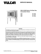
Disconnect the electrical power to the machine and follow lockout / tagout procedures.
1. Remove RIGHT SIDE PANEL.
2. Access fuses on side of output control assembly.
Fig. 29
• 1 - F3, 10 Amps, Time Delay
• 2 - F2, 1 Amp, Time Delay
• 3 - F1, 3.15 Amps, LED
TCM GAS COMBI OVEN - REMOVAL AND REPLACEMENT OF PARTS
F45909 Rev. B (0523) Page 20 of 113
• 4 - F5, 3.15 Amps, Status LED
• On bottom end, not shown - F4m 3.15 Amps, Status LED
3. Reverse procedure to install.
FUSES
/