Page is loading ...

HALF-SIZE CONVECTION OVENS
ELECTRIC ECO2D ML-114570
ECO2C ML-114572
GAS GCO2D ML-114573
GCO2C ML-114571
- NOTICE -
This Manual is prepared for the use of trained Hobart Service
Technicians and should not be used by those not properly
qualified.
This manual is not intended to be all encompassing. If you have
not attended a Hobart Service School for this product, you should
read, in its entirety, the repair procedure you wish to perform to
determine if you have the necessary tools, instruments and skills
required to perform the procedure. Procedures for which you do
not have the necessary tools, instruments and skills should be
performed by a trained Hobart Service Technician.
The reproduction, transfer, sale or other use of this manual,
without the express written consent of Hobart, is prohibited.
This manual has been provided to you by ITW Food Equipment
Group LLC ("ITW FEG") without charge and remains the property
of ITW FEG, and by accepting this manual you agree that you will
return it to ITW FEG promptly upon its request for such return at
any time in the future.
SERVICE MANUAL
A product of Vulcan-Hart 3600 North Point Blvd Baltimore, MD 21222
F24575 Rev. A (0620)

TABLE OF CONTENTS
SERVICE UPDATES ....................................................................................... 4
SERVICE UPDATES ................................................................................... 4
TIS DOCUMENT LIST - HALF SIZE CONVECTION OVENS ............................................. 4
GENERAL .................................................................................................. 6
INTRODUCTION ....................................................................................... 6
GENERAL .......................................................................................... 6
SPECIFICATIONS ...................................................................................... 6
TOOLS ................................................................................................. 6
REMOVAL AND REPLACEMENT OF PARTS ............................................................... 7
COVERS AND PANELS ................................................................................ 7
TOP FRONT COVER ............................................................................... 7
CONTROL PANEL ................................................................................. 7
RIGHT SIDE PANEL ................................................................................ 7
CONTROL PANEL COMPONENTS ..................................................................... 7
REMOVABLE COMPONENTS ...................................................................... 7
PROCEDURE ...................................................................................... 7
BLOWER AND/OR BLOWER MOTOR (UP TO S/N GAS: 481929306 ELECTRIC: 481929289) ........... 8
BLOWER AND/OR BLOWER MOTOR (AFTER S/N GAS: 481929307 ELECTRIC: 481929290) ........... 9
HEAT EXCHANGER (GAS OVENS) ................................................................... 10
BURNER (GAS OVENS UP TO S/N GAS: 481929306) ................................................. 11
BURNER (AFTER S/N GAS: 481929307) .............................................................. 12
GAS VALVE (SOLENOID) (GAS OVENS) .............................................................. 13
HEATING ELEMENTS (ELECTRIC OVENS) ........................................................... 13
TEMPERATURE PROBE .............................................................................. 14
OVEN DOOR (UP TO S/N GAS: 481929306 ELECTRIC: 481929289) ................................... 14
REMOVAL ........................................................................................ 14
DISASSEMBLY ................................................................................... 15
OVEN DOOR (AFTER S/N GAS: 481929307 ELECTRIC: 481929290) .................................. 15
DOOR CHAIN ADJUSTMENT (SIMULATANEOUS DOORS) ........................................... 16
DOOR SWITCH (UP TO S/N GAS: 481929306 ELECTRIC: 481929289) ................................ 16
DOOR SWITCH (AFTER S/N GAS: 481929307 ELECTRIC: 481929290) ................................ 17
SERVICE PROCEDURES AND ADJUSTMENTS ........................................................... 18
TEMPERATURE PROBE TEST (ALL MODELS) ....................................................... 18
VERIFICATION OF SPARK AT SPARK PROBE ........................................................ 18
GAS PRESSURE ADJUSTMENT ...................................................................... 19
SPARK IGNITION CONTROL TEST ................................................................... 19
NO GAS IGNITION & NO SPARKING .............................................................. 20
NO GAS IGNITION & NO SPARKING .............................................................. 20
SOLID STATE CONTROL TEST ....................................................................... 20
SOLID STATE CONTROL CALIBRATION .............................................................. 21
DOOR SWITCH ADJUSTMENT (UP TO S/N GAS: 481929306 ELECTRIC: 481929289) ................ 22
DOOR SWITCH ADJUSTMENT (AFTER S/N GAS: 481929307 ELECTRIC: 481929290) ................ 22
DOOR REVERSAL .................................................................................... 23
DOOR ADJUSTMENT (UP TO S/N GAS: 481929306 ELECTRIC: 481929289) .......................... 24
DOOR ADJUSTMENT (AFTER S/N GAS: 481929307 ELECTRIC: 481929290) ......................... 24
BLOWER ADJUSTMENT (UP TO S/N GAS: 481929306 ELECTRIC: 481929289) ....................... 25
BLOWER ADJUSTMENT (AFTER S/N GAS: 481929307 ELECTRIC: 481929290) ...................... 25
ELECTRONIC CONTROL ............................................................................. 25
HEATING ELEMENT TEST ............................................................................ 26
ELECTRICAL OPERATION ................................................................................ 27
COMPONENT FUNCTION ............................................................................ 27
COMPONENT LOCATION ............................................................................. 27
SEQUENCE OF OPERATION - GAS OVEN ........................................................... 29
HALF-SIZE CONVECTION OVENS
F24575 Rev. A (0620) Page 2 of 50

IGNITION MODULE ............................................................................... 29
SOLID STATE CONTROL ......................................................................... 29
ELECTRONIC CONTROL ......................................................................... 30
COOLDOWN ...................................................................................... 30
SEQUENCE OF OPERATION - ELECTRIC OVEN ..................................................... 31
SOLID STATE CONTROL ......................................................................... 31
ELECTRONIC CONTROL ......................................................................... 31
COOLDOWN ...................................................................................... 32
SCHEMATICS GAS OVENS ........................................................................... 33
WIRING DIAGRAM - GAS OVENS ..................................................................... 36
SCHEMATICS - ELECTRIC OVENS ................................................................... 41
WIRING DIAGRAM - ELECTRIC OVENS .............................................................. 44
TROUBLESHOOTING ..................................................................................... 49
ELECTRIC OVENS .................................................................................... 49
GAS OVENS .......................................................................................... 49
HALF-SIZE CONVECTION OVENS
© VULCAN 2020
Page 3 of 50 F24575 Rev. A (0620)

SERVICE UPDATES
SERVICE UPDATES
June 2019
• Updated SPECIFICATIONS.
• Added BLOWER AND/OR BLOWER MOTOR (AFTER S/N GAS: 481929307 ELECTRIC: 481929290)
• Added BURNER (AFTER S/N GAS: 481929307).
• Added OVEN DOOR (AFTER S/N GAS: 481929307 ELECTRIC: 481929290).
• Added DOOR SWITCH (AFTER S/N GAS: 481929307 ELECTRIC: 481929290).
• Added DOOR SWITCH ADJUSTMENT (AFTER S/N GAS: 481929307 ELECTRIC: 481929290).
• Added DOOR ADJUSTMENT (AFTER S/N GAS: 481929307 ELECTRIC: 481929290).
• Added BLOWER ADJUSTMENT (AFTER S/N GAS: 481929307 ELECTRIC: 481929290).
• Updated SCHEMATICS GAS OVENS.
• Updated WIRING DIAGRAM - GAS OVENS.
• Updated SCHEMATICS - ELECTRIC OVENS.
• Updated WIRING DIAGRAM - ELECTRIC OVENS.
TIS DOCUMENT LIST - HALF SIZE CONVECTION OVENS
SERVICE TAB
Document Title Document Type
Half Size Convection Ovens and Gas Service Manual Service Manual
Setting the Igniter Gap Service Kit Instructions (SKI)
Gas Connections & BTU Flow Capacity Technical Service Bulletin (TSB)
Machine Data Code Information Technical Service Bulletin (TSB)
SERVICE TAB (Multimedia)
Document Title Document Type
3700 Oven Quick Start Guide Operator
HCEC20 & HEC20D Electric Convection Ovens (ML's 114574 & 114576)
Instructions Instructions
Repair Flood-Damaged Equipment Misc
Convection Oven Computer Control Guide Operator
Convection Ovens Gas & Electric Service Instructions
Stand Instructions - Half Size Convection Oven Service Instructions
Rating Plate Locations on Current Vulcan-Hart/Wolf Range Equipment Technical Service Bulletin (TSB)
SB770R Door Latch Change on Full Size Convection Ovens (VC4, VC6,
SG, WKG, & WKE) Technical Service Bulletin (TSB)
HALF-SIZE CONVECTION OVENS - SERVICE UPDATES
F24575 Rev. A (0620) Page 4 of 50

SERVICE TAB (Multimedia)
SB880 Independent Door Handle Assembly for Convection Ovens Technical Service Bulletin (TSB)
TSB 1037A Hobart to Vulcan "Common" Model Cross Reference List Technical Service Bulletin (TSB)
TSB 0874 Full Size Convection Ovens - Lighting & Cooling Fan Technical Service Bulletin (TSB)
TSB 0930 Gas Convection Ovens, Blower Motor & Wheel Change Technical Service Bulletin (TSB)
TSB 1004E All Half Size & Full Size Unites w/Independent Opening Doors
-Enhanced Door Catch Info. Technical Service Bulletin (TSB)
TSB 1290 HEC. HGC, VEC, VGC Conveyor Ovens - New Temperature
Control Technical Service Bulletin (TSB)
PARTS TAB
Document Title Document Type
Half Size Electric Convection Ovens Parts Catalog Parts Catalog
HALF-SIZE CONVECTION OVENS - SERVICE UPDATES
Page 5 of 50 F24575 Rev. A (0620)

GENERAL
INTRODUCTION
General
This manual will cover half-size electric and gas
convection ovens that use either a solid state control
or an electronic control.
Procedures in this manual are applicable to both gas
and electric ovens unless specified.
SPECIFICATIONS
GAS OVENS
GAS DATA ELECTRICAL DATA
INPUT BTU/HR MANIFOLD PRESSURE LOAD (Watts) AMP/LINE
NATURAL PROPANE NATURAL PROPANE 120V
SINGLE OVEN 2500 2500 3.5" W.C. 10" W.C. 950 8
DOUBLE
OVEN 5000 5000 3.5" W.C. 10" W.C. 1900 16
ELECTRIC OVENS
TOTAL
KW
3-PHASE LOADING
(KW PER PHASE)
NOMINAL AMPS PER LINE WIRE
3 PHASE 1 PHASE
208V 240V 208V 240V
L1-L2 L2-L3 L1-L3 L1 L2 L3 L1 L2 L3
SINGLE
OVEN 5.5 2.5 0 3.0 22.9 10.4 12.5 19.9 9.0 10.9 26.5 23.0
DOUBLE
OVEN 11.0 5.0 0 6.0 45.8 20.8 25.0 39.7 18.0 21.7 52.9 45.9
TOOLS
Standard
• Standard set of hand tools.
• VOM with minimum of NFPA-70E CATIII 600V, UL/CSA/TUV listed. Sensitivity of at least 20,000 ohms per
volt and the ability to measure DC micro amps. Meter leads must also be rated at CAT III 600V.
• Clamp on type amp meter with minimum of NFPA-70E CAT III 600V,UL/CSA/TUV listed.
• Temperature tester (thermocouple type).
• ESD (Electrostatic discharge) Protection Kit.
Special
• Hazardous gas leak tester.
• Manometer (Gas Ovens).
HALF-SIZE CONVECTION OVENS - GENERAL
F24575 Rev. A (0620) Page 6 of 50

REMOVAL AND REPLACEMENT OF PARTS
COVERS AND PANELS
Disconnect the electrical power to
the machine and follow lockout /
tagout procedures.
Shut off the gas before servicing the
unit and follow lockout / tagout
procedures.
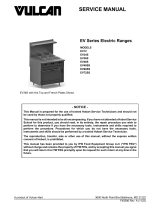
Top Front Cover
1. The top front cover is secured with four screws,
two on each side of cover. Remove these screws
then pull cover off unit.
Fig. 1
2. Reverse the procedure to install.
Bottom Front Cover
1. The bottom front cover is secured with four (4)
screws, two on each side of cover. Remove these
screws then remove the cover from the oven.
Fig. 2
2. Reverse the procedure to install.
Control Panel
1. On gas models, remove the handle from the
manual gas valve.
2. Remove the three screws from the left front and
loosen the three screws on the right side of the
control panel.
3. Pull the panel away from the oven.
Fig. 3
4. Unplug the lead wires to the control panel
components and disconnect the temperature
probe leads.
5. Reverse the procedure to install.
Right Side Panel
1. Remove the three screws which secure the right
side of the control panel.
2. Loosen the two screws on the right side of the top
front cover.
3. Remove the remaining eight screws securing the
right side panel.
Fig. 4
4. Pull the right side panel out at the bottom then
down to remove.
5. Reverse the procedure to install.
CONTROL PANEL COMPONENTS
Removable Components
Listed on the illustrations TSP1001C & TSP1046C
Procedure
1. Remove CONTROL PANEL COVER.
HALF-SIZE CONVECTION OVENS - REMOVAL AND REPLACEMENT OF PARTS
Page 7 of 50 F24575 Rev. A (0620)

Fig. 5
Fig. 6
2. Disconnect wire leads at the component to be
replaced.
3. Remove component.
4. Reverse procedure to install.
5. Verify proper oven operation.
BLOWER AND/OR BLOWER
MOTOR (UP TO S/N GAS:
481929306 ELECTRIC: 481929289)
Disconnect the electrical power to
the machine and follow lockout /
tagout procedures.
1. Remove racks and the right rack support.
2. Remove baffle panel by lifting up and out.
3. For gas ovens only, remove HEAT
EXCHANGER (GAS OVENS).
Fig. 7
4. Loosen set screws on blower hub.
HALF-SIZE CONVECTION OVENS - REMOVAL AND REPLACEMENT OF PARTS
F24575 Rev. A (0620) Page 8 of 50

Fig. 8
5. Remove blower from motor shaft.
NOTE: Bearing puller may be necessary.
If the blower only is to be replaced, reverse
procedure to install and perform BLOWER
ADJUSTMENT (UP TO S/N GAS: 481929306
ELECTRIC: 481929289).
6. Remove RIGHT SIDE PANEL.
7. Note and disconnect motor wires.
A. P1 (purple) to wire # 11.
B. Orange (low speed) to wire # 12.
C. Blue (high speed) to wire # 13.
D. Red wires connected together.
8. Remove motor mounting bolts securing motor to
mounting plate and remove from oven.
Fig. 9
9. Place new motor on mounting plage and route
wiring through grommet in component panel.
10. Install mounting pads and bolts. DO NOT tighten
mounting bolts.
11. Slide blower onto motor shaft until hub is flush
with end of shaft and tighten set screws .
12. Adjust motor position until blower is parallel to
oven cavity wall with a 1/4" spacing. Refer to:
BLOWER ADJUSTMENT (UP TO S/N GAS:
481929306 ELECTRIC: 481929289).
13. Tighten bolts.
14. Install baffle panel, rack guides and racks.
15. Verify proper oven operation.
BLOWER AND/OR BLOWER
MOTOR (AFTER S/N GAS:
481929307 ELECTRIC: 481929290)
Disconnect the electrical power to
the machine and follow lockout /
tagout procedures.
1. Remove racks and the right rack support.
2. Remove baffle panel by lifting up and out.
3. For gas ovens only, remove HEAT
EXCHANGER.
Fig. 10
4. Loosen set screws on blower hub.
HALF-SIZE CONVECTION OVENS - REMOVAL AND REPLACEMENT OF PARTS
Page 9 of 50 F24575 Rev. A (0620)

Fig. 11
5. Remove blower from motor shaft.
NOTE: Bearing puller may be nesscessary.
If the blower only is to be replaced, reverse
procedure to install and perform BLOWER
ADJUSTMENT (UP TO S/N GAS: 481929306
ELECTRIC: 481929289).
6. Remove RIGHT SIDE PANEL.
7. Note and disconnect motor wire connector.
8. Remove four nuts that secure motor to oven.
Fig. 12
9. Place new motor on studs and install nuts.
10. Install mounting pads and bolts. DO NOT tighten
mounting bolts.
11. Install blower with 1/4" spacing. Refer to
BLOWER ADJUSTMENT (UP TO S/N GAS:
481929306 ELECTRIC: 481929289).
12. Tighten bolts.
13. Install baffle panel, rack guides and racks.
HEAT EXCHANGER (GAS OVENS)
Disconnect the electrical power to
the machine and follow lockout /
tagout procedures.
Shut off the gas before servicing the
unit and follow lockout / tagout
procedures.
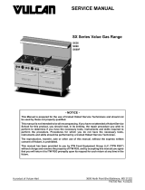
1. Remove racks and right rack support.
2. Remove baffle panel by lifting up and out.
3. Remove heat exchanger mounting screws and
remove from oven.
Fig. 13
4. Reverse procedure to install.
5. Verify proper oven operation.
HALF-SIZE CONVECTION OVENS - REMOVAL AND REPLACEMENT OF PARTS
F24575 Rev. A (0620) Page 10 of 50

BURNER (GAS OVENS UP TO S/N
GAS: 481929306)
Disconnect the electrical power to
the machine and follow lockout /
tagout procedures.
Shut off the gas before servicing the
unit and follow lockout / tagout
procedures.
1. Remove racks and the right rack support.
2. Remove baffle panel by lifting up and out.
3. Remove RIGHT SIDE PANEL.
4. Remove CONTROL PANEL.
5. Remove HEAT EXCHANGER.
6. Remove BLOWER AND/OR BLOWER MOTOR
(UP TO S/N GAS: 481929306 ELECTRIC:
481929289).
7. Remove motor mount cover (1, Fig. 14).
Fig. 14
8. Remove inner right hand side inside (1, Fig. 15)
and outer (2, Fig. 15) mounting screws.
Fig. 15
9. Remove inner right side.
Fig. 16
10. Remove burner.
HALF-SIZE CONVECTION OVENS - REMOVAL AND REPLACEMENT OF PARTS
Page 11 of 50 F24575 Rev. A (0620)

Fig. 17
11. Reverse procedure to install.
NOTE: When installed, the electrodes are positioned
toward the front of the oven.
Fig. 18
12. Verify proper oven operation.
BURNER (AFTER S/N GAS:
481929307)
Shut off the gas before servicing the
unit and follow lockout / tagout
procedures.
Disconnect the electrical power to
the machine and follow lockout /
tagout procedures.
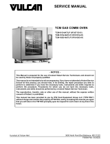
1. Remove RIGHT SIDE PANEL.
2. Remove nut holding orifice assembly (1, Fig.
19).
Fig. 19
3. Disconnect lead wires to electrode assembly (2,
Fig. 19).
4. Remove burner assembly (1, Fig. 20) mounting
screws.
Fig. 20
HALF-SIZE CONVECTION OVENS - REMOVAL AND REPLACEMENT OF PARTS
F24575 Rev. A (0620) Page 12 of 50

5. Pull burner assembly out.
6. Remove ignitor.
7. Reverse procedure to install.
8. Verify proper oven operation.
GAS VALVE (SOLENOID) (GAS
OVENS)
Disconnect the electrical power to
the machine and follow lockout /
tagout procedures.
Shut off the gas before servicing the
unit and follow lockout / tagout
procedures.
All gas joints disturbed during servicing must be
checked for leaks. Check with a soap and water
solution (bubbles). Do not use an open flame.
1. Remove RIGHT SIDE PANEL. .
2. Disconnect the lead wires at the gas valve.
3. Disconnect the gas line fitting going to the burner
at the top of the gas valve.
4. Remove the gas valve from the nipple between
the it and the manual gas valve.
Fig. 21
5. Reverse procedure to install.
6. Adjust the gas valve as outlined under “GAS
PRESSURE ADJUSTMENT”.
HEATING ELEMENTS (ELECTRIC
OVENS)
Disconnect the electrical power to
the machine and follow lockout /
tagout procedures.
1. Remove racks and the right rack support.
2. Remove baffle panel by lifting up and out.
3. Remove the Right Side Panel as outlined under
“COVERS AND PANELS”.
4. Disconnect the lead wires to the heating
elements.
5. Remove the screws from the clamps that secure
the heating element assembly.
HALF-SIZE CONVECTION OVENS - REMOVAL AND REPLACEMENT OF PARTS
Page 13 of 50 F24575 Rev. A (0620)

Fig. 22
6. Pull the top of the heating element assembly into
the oven cavity until the ends of the elements are
inside the oven cavity. Lift up and remove the
lower clamp from between the side wall and the
bottom of the oven cavity.
7. Remove the clamps from the heating element
assembly and replace the element(s).
8. Reverse procedure to install.
TEMPERATURE PROBE
Disconnect the electrical power to
the machine and follow lockout /
tagout procedures.
1. Remove the Control Panel as outlined under
"COVERS AND PANELS".
2. Disconnect the probe leads at the temperature
control.
3. Remove probe from the probe guard and push it
thru the oven wall into the control panel area.
NOTE: When installing, only the metal surface of the
probe should be inserted into the probe guard.
Fig. 23
NOTE: The probe may have to be inserted at an
angle. The hole in the inside oven cavity wall may not
line up straight with the oven cavity outer shell.
4. Reverse the procedure to install the new probe.
5. Adjust the temperature control as outlined under
SOLID STATE CONTROL CALIBRATION or
ELECTRONIC CONTROL in "SERVICE
PROCEDURES AND ADJUSTMENTS".
OVEN DOOR (UP TO S/N GAS:
481929306 ELECTRIC: 481929289)
Disconnect the electrical power to
the machine and follow lockout /
tagout procedures.
Removal
1. Remove TOP FRONT COVER.
2. Remove door switch lever from door shaft.
3. Remove door switch bracket.
Fig. 24
4. While supporting the door, remove bearing, door
plate and spacer.
HALF-SIZE CONVECTION OVENS - REMOVAL AND REPLACEMENT OF PARTS
F24575 Rev. A (0620) Page 14 of 50

Fig. 25
5. Lift door from the lower bearing.
6. Reverse procedure to install door assembly and
check DOOR ADJUSTMENT (UP TO S/N GAS:
481929306 ELECTRIC: 481929289).
Disassembly
1. Open door.
2. Remove door handle and latch plate.
3. Remove screws which secure the inner and outer
door panels to door frame.
Fig. 26
4. Remove inner and outer door panel.
5. Remove four screws and lift window assembly
out.
NOTE: Use high temperature silicone between the
window and the door panel.
Fig. 27
6. Reverse procedure to install the new window and
perform DOOR ADJUSTMENT (UP TO S/N
GAS: 481929306 ELECTRIC: 481929289).
OVEN DOOR (AFTER S/N GAS:
481929307 ELECTRIC: 481929290)
Disconnect the electrical power to
the machine and follow lockout /
tagout procedures.
1. Remove TOP FRONT COVER and BOTTOM
COVER.
2. Remove door switch lever arm from door shaft.
Fig. 28
3. With door closed, support door while carefully
removing upper door support mounting screws.
HALF-SIZE CONVECTION OVENS - REMOVAL AND REPLACEMENT OF PARTS
Page 15 of 50 F24575 Rev. A (0620)

Fig. 29
4. Slide upper door support bracket off door shaft.
5. Lift door out of lower door support.
6. Reverse procedure to install.
DOOR CHAIN ADJUSTMENT
(SIMULATANEOUS DOORS)
Introduction
When the oven doors are in proper adjustment,
as the doors come together, the right door will
lead the left door in closing by about 1/4 inch. The
doors will feel like they are self closing the last
1/2 inch of travel.
Procedure
1. Remove the lower sill cover.
2. Close doors and check door chain for factory
setting.
A. Turnbuckles should be 5 to 5 1/2 inches
apart.
B. Short eye bolt should be connected to the
end of the chain that goes to the front of the
sprocket.
C. 2 links of the chain should not be engaged
at the rear of the sprocket.
D. Chain must be tight enough that the doors
move simultaneously when opened or
closed.
E. When the doors are opened, the
turnbuckles will move away from each other.
F. The stop cable must be positioned where it
moves freely and does not get pinched.
3. Position door chain assembly to factory setting if
the conditions in step 2 are not met.
Fig. 30
4. If right door does not lead the left door in closing:
A. Loosen locknuts on both turnbuckles.
B. Loosen left turnbuckle.
C. Tighten right turnbuckle.
D. Tighten locknuts on both turnbuckles.
5. If the right door leads the left door by more than
3/8 inch:
A. Loosen locknuts on both turnbuckles.
B. Loosen right turnbuckle.
C. Tighten left turnbuckle.
D. Tighten locknuts on both turnbuckles.
6. Check door for proper operation.
NOTE: The locknuts must be tight during testing or
the adjustment will not hold.
A. If doors do not close properly, repeat step 4,
5 and 6.
B. If doors operate properly, continue to step 7.
7. Install the lower front cover.
DOOR SWITCH (UP TO S/N GAS:
481929306 ELECTRIC: 481929289)
Disconnect the electrical power to
the machine and follow lockout /
tagout procedures.
1. Remove TOP FRONT COVER.
2. Disconnect the leads to door switch.
3. Remove switch mounting screws.
HALF-SIZE CONVECTION OVENS - REMOVAL AND REPLACEMENT OF PARTS
F24575 Rev. A (0620) Page 16 of 50

4. Remove switch which is secured by two screws.
Fig. 31
5. Reverse the procedure to install.
6. Perform DOOR SWITCH ADJUSTMENT.
DOOR SWITCH (AFTER S/N GAS:
481929307 ELECTRIC: 481929290)
Disconnect the electrical power to
the machine and follow lockout /
tagout procedures.
1. Remove TOP FRONT COVER and BOTTOM
FRONT COVER.
2. Disconnect leads (1, Fig. 32) to door switch.
Fig. 32
3. Remove door switch bracket mounting screws
(2, Fig. 32).
4. Reverse the procedure to install new switch.
5. Perform DOOR SWITCH ADJUSTMENT.
6. Verify proper oven operation.
HALF-SIZE CONVECTION OVENS - REMOVAL AND REPLACEMENT OF PARTS
Page 17 of 50 F24575 Rev. A (0620)

SERVICE PROCEDURES AND ADJUSTMENTS
Certain procedures in this section require electrical test or measurements while power is
applied to the machine. Exercise extreme caution at all times and follow Arc Flash procedures.
If test points are not easily accessible, disconnect power and follow Lockout/Tagout
procedures, attach test equipment and reapply power to test.
TEMPERATURE PROBE TEST (ALL
MODELS)
Disconnect the electrical power to
the machine and follow lockout /
tagout procedures.
1. Remove the Right Side Panel as outlined under
"COVERS AND PANELS".
2. Remove the probe lead wires from the electronic
control.
3. Test the probe with an ohmmeter.
TEMPERATURE in °F RESISTANCE in Ω ±10%
77 90000
240 4077
260 3016
280 3266
300 1726
320 1332
340 1041
360 822
380 656
400 529
425 424
450 334
475 266
VERIFICATION OF SPARK AT
SPARK PROBE
Disconnect the electrical power to
the machine and follow lockout /
tagout procedures.
Shut off the gas before servicing the
unit and follow lockout / tagout
procedures.
1. Remove the Right Side Panel and Control
Panel as outlined under “COVERS AND
PANELS”.
2. Disconnect the high voltage lead from the
electrode.
DO NOT HOLD THE WIRE WITH YOUR HANDS
FOR THIS TEST. THE MANUAL GAS VALVE MUST
BE CLOSED
3. Clamp the wire in such a manner that the end of
the wire is 3/16" from the frame of the oven.
NOTE: It is critical that the wire be held 3/16" away
from the oven or sparking may not occur even though
the probe circuits are functioning properly.
HALF-SIZE CONVECTION OVENS - SERVICE PROCEDURES AND ADJUSTMENTS
F24575 Rev. A (0620) Page 18 of 50

Fig. 33
THE FOLLOWING STEPS REQUIRE POWER TO
BE APPLIED TO THE UNIT DURING THE TEST.
USE EXTREME CAUTION AT ALL TIMES.
4. Plug the unit in and set the temperature controller
to the maximum setting.
5. Turn the power switch on.
6. Sparking should occur after a 15 second purge
time. Arcing from the lead wire to the oven frame
should be observed at this time.
GAS PRESSURE ADJUSTMENT
Disconnect the electrical power to
the machine and follow lockout /
tagout procedures.
Shut off the gas before servicing the
unit and follow lockout / tagout
procedures.
1. Remove the Right Side Panel and Control
Panel as outlined under “COVERS AND
PANELS”.
2. Remove the plug from the test port and install the
manometer.
THE FOLLOWING STEPS REQUIRE POWER TO
BE APPLIED TO THE UNIT DURING THE TEST.
USE EXTREME CAUTION AT ALL TIMES.
3. Plug in the unit and turn on the gas.
4. Set the temperature control to the highest setting
and turn the power switch on. The burner must
be lit while adjusting the pressure.
5. Turn the adjustment screw to obtain the proper
gas pressure.
Fig. 34
• Turn screw clockwise to increase pressure.
• Turn screw counterclockwise to decrease
pressure.
GAS TYPE SETTING AT OUTPUT
OF GAS VALVE
Natural 3.5 inches W.C.
Propane 10 inches W.C.
NOTE: If input pressure is below 4.0 (Natural) or 10.5
(Propane) inches W.C., the desired output cannot be
obtained and the oven will overate at a lower BTU.
SPARK IGNITION CONTROL TEST
Disconnect the electrical power to
the machine and follow lockout /
tagout procedures.
NOTE: Verify that the ground terminal is connected
to the oven ground.
HALF-SIZE CONVECTION OVENS - SERVICE PROCEDURES AND ADJUSTMENTS
Page 19 of 50 F24575 Rev. A (0620)

No gas ignition & no sparking
1. Remove the Right Side Panel as outlined under
“COVERS AND PANELS”.
2. Plug in the unit and set the temperature controller
to 350°.
3. Turn the power switch on.
4. Check for 24 VAC between the power terminal
and ground terminal.
A. If 24 VAC is present, replace the spark
ignition control.
B. If 24 VAC is not present, check the
transformer, temperature controller, and
switches.
No gas ignition & no sparking
1. Remove the Right Side Panel as outlined under
“COVERS AND PANELS”.
2. Plug in the unit and set the temperature controller
to 350°.
3. Turn the power switch on.
4. Check for 24 VAC between the power terminal
and ground terminal. The voltage should be
present after the 15 second purge and during the
10 second ignition period.
A. If 24 VAC is present, replace the spark
ignition control.
B. If 24 VAC is not present, check the
transformer, temperature controller, and
switches.
SOLID STATE CONTROL TEST
Certain procedures in this section
require electrical test or
measurements while power is
applied to the machine. Exercise
extreme caution at all times and
follow Arc Flash procedures. If test
points are not easily accessible,
disconnect power and follow
Lockout/Tagout procedures, attach
test equipment and reapply power to
test.
1. Remove the RIGHT SIDE PANEL.
NOTE: If right side panel is not accessible, this
component can be serviced by removing CONTROL
PANEL.
2. Place a thermocouple in the geometric center of
the oven cavity.
NOTE: Oven temperature must be below 450°F.
NOTE: If oven is equipped with "Cook and Hold"
option, set to Cook (normal cooking) before
continuing.
3. Set the temperature control to the maximum
setting.
4. Check machine data plate for correct voltage to
oven. Refer to diagram below for proper terminal
locations and voltages before checking the
control. Use the correct terminals for the
corresponding voltage.
5. Turn the power switch to ON.
Fig. 35
6. Check for proper voltage across terminals COM
AC to 120VAC or COM AC to 208-240VAC for
power to the control.
A. If correct, proceed to step 7.
B. If incorrect, problem is not with the
temperature control. See
TROUBLESHOOTING.
7. Check relay voltages on the board:
A. For 120VAC controls - check across
OUTPUT RELAY terminal (left side) to 120
VAC terminal for input to the internal relay.
Check across OUTPUT RELAY terminal
(right side) to 120 VAC for output from the
internal relay.
HALF-SIZE CONVECTION OVENS - SERVICE PROCEDURES AND ADJUSTMENTS
F24575 Rev. A (0620) Page 20 of 50
/