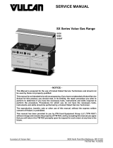
Vulcan-Hart VCBB36C User manual

Type
User manual

This manual is also suitable for

V SERIES HDR GAS RANGES
TOPS Open Top
Hot Top
Griddle Top
Work Surface
BASES Standard Oven
Convection Oven
Cabinet Base
- NOTICE -
This Manual is prepared for the use of trained Hobart Service
Technicians and should not be used by those not properly
qualified.
This manual is not intended to be all encompassing. If you have
not attended a Hobart Service School for this product, you should
read, in its entirety, the repair procedure you wish to perform to
determine if you have the necessary tools, instruments and skills
required to perform the procedure. Procedures for which you do
not have the necessary tools, instruments and skills should be
performed by a trained Hobart Service Technician.
The reproduction, transfer, sale or other use of this manual,
without the express written consent of Hobart, is prohibited.
This manual has been provided to you by ITW Food Equipment
Group LLC ("ITW FEG") without charge and remains the property
of ITW FEG, and by accepting this manual you agree that you will
return it to ITW FEG promptly upon its request for such return at
any time in the future.
SERVICE MANUAL
A product of Vulcan-Hart 3600 North Point Blvd Baltimore, MD 21222
F37418 Rev. A (0619)
TABLE OF CONTENTS
SERVICE UPDATES ....................................................................................... 4
SERVICE UPDATES ................................................................................... 4
TIS DOCUMENT LIST - V SERIES HDR GAS RANGES ................................................. 4
GENERAL .................................................................................................. 6
INTRODUCTION ....................................................................................... 6
INSTALLATION, OPERATION AND CLEANING ......................................................... 6
TOOLS ................................................................................................. 6
SPECIFICATIONS ...................................................................................... 6
REMOVAL AND REPLACEMENT OF PARTS ............................................................... 8
PILOT SAFETY VALVE AND TEMPERATURE CONTROL ASSEMBLY (S MODEL) ...................... 8
MANIFOLD COVER ................................................................................... 10
BULL NOSE .......................................................................................... 11
KICK PANEL .......................................................................................... 12
OVEN CAVITY BOTTOM PANEL (S MODEL) .......................................................... 12
OVEN CONTROL PANEL COVER ..................................................................... 13
PILOT SAFETY VALVE (S MODEL) ................................................................... 15
SOLENOID, PILOT SAFETY AND GAS SHUT-OFF VALVE ASSEMBLY (C MODEL) ................... 16
PILOT SAFETY VALVE (C MODEL) ................................................................... 18
TEMPERATURE CONTROL (THERMOSTAT) (S MODEL) ............................................. 19
TEMPERATURE CONTROL (THERMOSTAT) C MODEL) .............................................. 20
SOLENOID (C MODEL) ............................................................................... 23
MANUAL GAS SHUT-OFF VALVE (C MODEL) ......................................................... 23
OVEN PILOT ASSEMBLY (C MODEL) ................................................................. 24
OVEN PILOT ASSEMBLY (S MODELS) ............................................................... 25
OVEN BURNER ASSEMBLY .......................................................................... 26
PILOT QUICK DISCONNECT VALVE .................................................................. 28
TOP SECTION BURNER (OPEN TOP) ................................................................ 29
TOP SECTION BURNER (CHAR BROILER) ........................................................... 31
CHARBROILER PILOT ................................................................................ 33
TOP SECTION BURNER (FRENCH/HOT TOP) ........................................................ 34
TOP SECTION BURNER CONTROL VALVE ........................................................... 35
CONVECTION MOTOR FAN CONTROL SWITCH (C MODEL) ......................................... 35
CONVECTION MOTOR (C MODEL) ................................................................... 36
OVEN DOOR ......................................................................................... 37
OVEN DOOR COUNTER WEIGHT AND BEARING BLOCK ............................................ 38
OVEN DOOR MICROSWITCH (C MODEL) ............................................................ 40
GRIDDLE THERMOSTAT-COMBO VALVE ............................................................ 41
GRIDDLE PILOT ASSEMBLY ......................................................................... 43
GRIDDLE BURNER ORIFICE ......................................................................... 43
SERVICE PROCEDURES AND ADJUSTMENTS ........................................................... 45
GAS LEAK CHECK .................................................................................... 45
GAS PRESSURE CHECK ............................................................................. 45
GAS PRESSURE REGULATOR ADJUSTMENT (OPTIONAL) .......................................... 45
OVEN PILOT FLAME CHECK AND ADJUSTMENT .................................................... 46
TOP BURNER PILOT ................................................................................. 46
OVEN BURNER NOZZLE AND GAS ORIFICE CHECK ................................................. 47
AIR SHUTTER ADJUSTMENT ......................................................................... 47
TOP BURNER ADJUSTMENT ......................................................................... 47
OVEN BURNER ADJUSTMENT ....................................................................... 48
OVEN DOOR MICROSWITCH TEST (C MODEL) ...................................................... 48
FAN CONTROL SWITCH (C MODEL) ................................................................. 49
SOLENOID TEST (C MODEL) ......................................................................... 49
BURNER AIR SHUTTER ADJUSTMENT ............................................................... 50
CHARBROILER PILOT ADJUSTMENT ................................................................ 51
V SERIES HDR GAS RANGES
F37418 Rev. A (0619) Page 2 of 58
GRIDDLE THERMOSTAT-COMBO VALVE CALIBRATION ............................................. 51
OPERATION ...................................................................................... 51
CALIBRATION .................................................................................... 51
BY-PASS FLAME ADJUSTMENT ...................................................................... 52
TEMPERATURE CONTROL CALIBRATION ........................................................... 53
ELECTRICAL OPERATION ................................................................................ 55
COMPONENT FUNCTION ............................................................................ 55
SEQUENCE OF OPERATION (C MODEL) ............................................................. 55
WIRING DIAGRAM .................................................................................... 57
TROUBLESHOOTING ..................................................................................... 58
TROUBLESHOOTING CHART ........................................................................ 58
V SERIES HDR GAS RANGES
© VULCAN 2019
Page 3 of 58 F37418 Rev. A (0619)
SERVICE UPDATES
SERVICE UPDATES
February, 2019
• Service Manual moved into TIS from Multimedia at Rev 2 (12/09). Photos added to service manual. Up to
revision C.
TIS DOCUMENT LIST - V SERIES HDR GAS RANGES
SERVICE TAB
Document Title Document Type
V SERIES HDR GAS RANGES Service Manual Service Manual
V SERIES HEAVY DUTY GAS RANGES WITH OPEN
TOP BURNERS - PILOT ASSEMBLY CHANGE
Technical Service Bulletin (TSB)
SERVICE TAB (Multimedia)
Document Title Document Type
Wolf Heavy Duty Gas Operated Taco Range Instruction Manual Instructions
FD-0 Field Information Bulletin Misc
Repair Flood-Damaged Equipment Misc
V Series Gas Ranges Operator
HDR Top Section Removal & Installation Instructions Service Instructions
Pilot and Burner Problems on Units Without Powered Burners Service
Information
Vulcan Ranges (Gas) Service Information Service Instructions
Rating Plate Locations on Current Vulcan-Hart/Wolf Range Equipment
Fundamentals of Gas Technical Service Bulletin (TSB)
SB 1027 V Series HD Ranges Oven Pilot Baffle Installation Technical Service Bulletin (TSB)
SB 1028 V Series Heavy Duty Ranges Griddle Bulb Placement Technical Service Bulletin (TSB)
SB 1039 D300 & V1401 Splash Guard & Latch Assembly Enhancement Technical Service Bulletin (TSB)
SB750 Endurance Range Oven Control Valve Pel Valve Calibration Test
Procedure
Technical Service Bulletin (TSB)
TSB 0842 4 Position/3 Heat Switch - Ranges, Ovens, Broilers Technical Service Bulletin (TSB)
TSB 1037A Hobart to Vulcan "Common" Model Cross Reference List Technical Service Bulletin (TSB)
TSB 1240 HOBART AND VULCAN GAS RANGES - SAFETY SHUTOFF
VALVE CHANGE
Technical Service Bulletin (TSB)
TSB 1311 Hobart & Vulcan Medium Gas Ranges with Electronic Ignition -
Enhanced Ignition Modules
Technical Service Bulletin (TSB)
TSB 1328A Hobart & Vulcan Medium Gas Ranges - BASO Safety Shutoff
Valve Changes
Technical Service Bulletin (TSB)
V SERIES HDR GAS RANGES - SERVICE UPDATES
F37418 Rev. A (0619) Page 4 of 58
SERVICE TAB (Multimedia)
RobertShaw FS Flane Switch Recall Vulcan & Wolf Equipment Effected -
PN 713933
Temporary Service Instructions (TSI)
Thermostat Capillary Installation Video Instructions
PARTS TAB
Document Title Document Type
V Series HDR Gas Ranges Parts Catalog Parts Catalog
V SERIES HDR GAS RANGES - SERVICE UPDATES
Page 5 of 58 F37418 Rev. A (0619)
GENERAL
INTRODUCTION
Procedures in this manual will apply to all models unless specified. Pictures and illustrations can be of any model
unless the picture or illustration needs to be model-specific. Before performing maintenance on the equipment,
thoroughly read this manual and carefully follow the instructions in the order given.
INSTALLATION, OPERATION AND CLEANING
For detailed installation, operation and cleaning instructions, refer to Installation and Operation Manual available
online at www.vulcanequipment.com.
TOOLS
Standard
• Standard set of hand tools.
• VOM with minimum of NFPA-70E CATIII 600V, UL/CSA/TUV listed. Sensitivity of at least 20,000 ohms per
volt and the ability to measure DC micro amps. Meter leads must also be rated at CAT III 600V.
• Clamp on type amp meter with minimum of NFPA-70E CAT III 600V,UL/CSA/TUV listed.
• Temperature tester (thermocouple type).
• ESD (Electrostatic discharge) Protection Kit.
Special
• Hazardous gas leak tester.
• Manometer.
• Thermocouple Adaptor (Closed circuit DC voltages (purchased locally) Adaptors vary between manufacturers.
SPECIFICATIONS
ELECTRICAL
Models Voltage Amps Frequency
Convection Models
120/60/1
OR
208/60/1
(Optional)
15 50/60
V SERIES HDR GAS RANGES - GENERAL
F37418 Rev. A (0619) Page 6 of 58
GAS LINE PRESSURES
Pressure Natural (in W.C.) Propane (in W.C.)
Inlet Supply 7.0 min. 11.0 min.
Operating 6.0 min. 10.0 min.
V SERIES HDR GAS RANGES - GENERAL
Page 7 of 58 F37418 Rev. A (0619)
REMOVAL AND REPLACEMENT OF PARTS
PILOT SAFETY VALVE AND
TEMPERATURE CONTROL
ASSEMBLY (S MODEL)
Disconnect the electrical power to
the machine and follow lockout /
tagout procedures.
Shut off the gas before servicing the
unit and follow lockout / tagout
procedures.
1. Disconnect supply power and gas.
2. Remove OVEN CONTROL PANEL COVER.
3. Remove thermocouple (1, Fig. 1).
Fig. 1
4. Disconnect flex lines (2, Fig. 1) from pilot safety
valve.
5. Disconnect flex line (1, Fig. 2) from top of
temperature control.
Fig. 2
6. Remove screws (Fig. 3) securing gas mount
bracket to oven.
V SERIES HDR GAS RANGES - REMOVAL AND REPLACEMENT OF PARTS
F37418 Rev. A (0619) Page 8 of 58
Fig. 3
7. Lift up gas mount bracket to release hook (1, Fig.
4) off inner tab (1, Fig. 5). Pull out pilot safety
valve and temperature control bracket assembly
from oven.
Fig. 4
Fig. 5
V SERIES HDR GAS RANGES - REMOVAL AND REPLACEMENT OF PARTS
Page 9 of 58 F37418 Rev. A (0619)
Clean pipe threads and apply thread sealant that
is suitable for use with propane gases.
All gas joints disturbed during servicing must be
checked for leaks. Check with a soap and water
solution (bubbles). Do not use an open flame.
8. Reverse procedure to install.
9. Verify proper oven operation.
MANIFOLD COVER
Disconnect the electrical power to
the machine and follow lockout /
tagout procedures.
Shut off the gas before servicing the
unit and follow lockout / tagout
procedures.
1. Disconnect supply power and gas.
2. Loosen setscrews (1, Fig. 6) in burner control
knobs and remove knobs.
Fig. 6
3. Remove drive screws (1, Fig. 7) on both sides
securing manifold cover in place and remove
cover.
Fig. 7
4. Remove end caps (2, Fig. 7), if applicable.
5. Remove both front ledge support screws on
angled brackets.
Fig. 8
6. Remove screws along bottom under crumb tray.
V SERIES HDR GAS RANGES - REMOVAL AND REPLACEMENT OF PARTS
F37418 Rev. A (0619) Page 10 of 58
Fig. 9
7. Reverse procedure to install.
BULL NOSE
Disconnect the electrical power to
the machine and follow lockout /
tagout procedures.
Shut off the gas before servicing the
unit and follow lockout / tagout
procedures.
1. Turn top burners and griddle off.
2. Remove front row of top burner grates on ranges
with open top burners.
3. Remove all screws securing bull nose to range.
Fig. 10
Fig. 11
NOTE: Fig. 11 Each side.
4. Lift bull nose off range.
5. Reverse procedure to install.
V SERIES HDR GAS RANGES - REMOVAL AND REPLACEMENT OF PARTS
Page 11 of 58 F37418 Rev. A (0619)
KICK PANEL
Disconnect the electrical power to
the machine and follow lockout /
tagout procedures.
Shut off the gas before servicing the
unit and follow lockout / tagout
procedures.
1. Disconnect supply power and gas.
2. Lift up and tilt kick panel forward to open.
Fig. 12
3. Remove bottom screw and loosen screw on top,
on one side.
Fig. 13
4. Slide kick panel to other side to disengage pin
from hinge to remove kick panel from range.
Fig. 14
5. Reverse procedure to install.
OVEN CAVITY BOTTOM PANEL (S
MODEL)
Disconnect the electrical power to
the machine and follow lockout /
tagout procedures.
Shut off the gas before servicing the
unit and follow lockout / tagout
procedures.
1. Disconnect supply power and gas.
2. Open oven door.
3. Remove racks (1, Fig. 15).
V SERIES HDR GAS RANGES - REMOVAL AND REPLACEMENT OF PARTS
F37418 Rev. A (0619) Page 12 of 58
Fig. 15
4. Lift and pull out rack guides (1, Fig. 16).
Fig. 16
5. Slide retaining latches around so they rest
against setscrew.
Fig. 17
6. Lift bottom panel up slightly and pull forward to
remove.
7. Reverse procedure to install.
8. Verify proper oven operation.
OVEN CONTROL PANEL COVER
Disconnect the electrical power to
the machine and follow lockout /
tagout procedures.
Shut off the gas before servicing the
unit and follow lockout / tagout
procedures.
1. Disconnect supply power and gas.
2. Open kick panel.
3. Loosen setscrews (5/32 allen wrench) from gas
shut-off knob (1, STANDARD MODEL,
CONVECTION MODEL) and temperature
control knob (2, STANDARD CONVECTION)
and remove.
V SERIES HDR GAS RANGES - REMOVAL AND REPLACEMENT OF PARTS
Page 13 of 58 F37418 Rev. A (0619)
Fig. 18
Fig. 19
4. Remove control panel mounting screw (1, Fig.
20).
V SERIES HDR GAS RANGES - REMOVAL AND REPLACEMENT OF PARTS
F37418 Rev. A (0619) Page 14 of 58
Fig. 20
5. Remove control panel by lifting up bottom and
releasing from tab (1, Fig. 21) on top of panel.
CONVECTION MODELS
: Carefully remove cover,
wiring connections exist between back of panel and
control panel bracket.
Fig. 21
6. Reverse procedure to install.
7. Verify proper oven operation.
PILOT SAFETY VALVE (S MODEL)
Disconnect the electrical power to
the machine and follow lockout /
tagout procedures.
Shut off the gas before servicing the
unit and follow lockout / tagout
procedures.
1. Disconnect supply power and gas.
2. Remove PILOT SAFETY VALVE AND
TEMPERATURE CONTROL ASSEMBLY (S
MODEL).
3. Remove union fitting (1, Fig. 22) and pipe fitting
(2, Fig. 22) from top and bottom of pilot safety
valve.
V SERIES HDR GAS RANGES - REMOVAL AND REPLACEMENT OF PARTS
Page 15 of 58 F37418 Rev. A (0619)
Fig. 22
4. Remove pilot safety valve from gas mount
bracket.
Fig. 23
5. Remove residual tape from fitting and pipe
nipple.
6. Apply new gas-rated Teflon tape to pipe nipple
and fitting.
Clean pipe threads and apply thread sealant that
is suitable for use with propane gases.
All gas joints disturbed during servicing must be
checked for leaks. Check with a soap and water
solution (bubbles). Do not use an open flame.
7. Reverse procedure to install.
8. Verify proper oven operation.
SOLENOID, PILOT SAFETY AND
GAS SHUT-OFF VALVE ASSEMBLY
(C MODEL)
Disconnect the electrical power to
the machine and follow lockout /
tagout procedures.
Shut off the gas before servicing the
unit and follow lockout / tagout
procedures.
1. Disconnect supply power and gas.
2. Remove OVEN CONTROL PANEL COVER.
3. Disconnect flex line from tee fitting (1, Fig. 24)
below manual gas shut-off valve.
PREVIOUS PRODUCTION
V SERIES HDR GAS RANGES - REMOVAL AND REPLACEMENT OF PARTS
F37418 Rev. A (0619) Page 16 of 58
Fig. 24
Fig. 25
CURRENT PRODUCTION
4. Disconnect flex line (2, Fig. 24) from top of
solenoid.
5. Remove screws (3, Fig. 24) securing gas mount
bracket.
V SERIES HDR GAS RANGES - REMOVAL AND REPLACEMENT OF PARTS
Page 17 of 58 F37418 Rev. A (0619)
6. Remove gas mount bracket with solenoid, pilot
safety and manual gas shut-off valve assembly
from oven.
7. Remove residual tape from fittings and pipe
nipples.
8. Apply new gas-rated thread sealant to pipe
nipples and fittings.
All gas joints disturbed during servicing must be
checked for leaks. Check with a soap and water
solution (bubbles). Do not use an open flame.
Clean pipe threads and apply thread sealant that
is suitable for use with propane gases.
9. Reverse procedure to install.
10. Verify proper oven operation.
PILOT SAFETY VALVE (C MODEL)
Disconnect the electrical power to
the machine and follow lockout /
tagout procedures.
Shut off the gas before servicing the
unit and follow lockout / tagout
procedures.
1. Disconnect supply power and gas.
2. Remove SOLENOID, PILOT SAFETY AND GAS
SHUT-OFF VALVE ASSEMBLY (C MODEL).
3. Remove fitting (1, Fig. 26) and flex line (2, Fig.
26) from pilot safety valve.
Fig. 26
4. Remove pilot safety valve from gas mount
bracket.
Fig. 27
5. Remove pipe nipple and manual gas shut-off
valve from pilot safety valve.
6. Remove residual tape from fittings and pipe
nipples.
7. Apply new gas-rated thread sealant to pipe
nipples and fittings.
All gas joints disturbed during servicing must be
checked for leaks. Check with a soap and water
solution (bubbles). Do not use an open flame.
8. Reverse procedure to install.
V SERIES HDR GAS RANGES - REMOVAL AND REPLACEMENT OF PARTS
F37418 Rev. A (0619) Page 18 of 58
9. Verify proper oven operation.
TEMPERATURE CONTROL
(THERMOSTAT) (S MODEL)
Disconnect the electrical power to
the machine and follow lockout /
tagout procedures.
All gas joints disturbed during servicing must be
checked for leaks. Check with a soap and water
solution (bubbles). Do not use an open flame.
1. Disconnect supply power and gas.
2. Remove PILOT SAFETY VALVE AND
TEMPERATURE CONTROL ASSEMBLY (S
MODEL).
3. Remove screw (1, Fig. 28) securing temperature
control to gas mount bracket.
Fig. 28
Remove capillary (2, Fig. 28).
4. Remove temperature control from pipe nipple.
Fig. 29
5. Remove residual tape from fitting and pipe
nipple.
6. Remove capillary.
A. Remove capillary bracket in oven cavity.
Fig. 30
B. Route capillary through oven cavity wall.
C. Reverse Step 6 to replace capillary.
7. Apply new gas-rated thread sealant to pipe
nipple and fitting.
V SERIES HDR GAS RANGES - REMOVAL AND REPLACEMENT OF PARTS
Page 19 of 58 F37418 Rev. A (0619)
Clean pipe threads and apply thread sealant that
is suitable for use with propane gases.
All gas joints disturbed during servicing must be
checked for leaks. Check with a soap and water
solution (bubbles). Do not use an open flame.
8. Reverse procedure to install.
9. Verify proper oven operation.
TEMPERATURE CONTROL
(THERMOSTAT) C MODEL)
Disconnect the electrical power to
the machine and follow lockout /
tagout procedures.
Shut off the gas before servicing the
unit and follow lockout / tagout
procedures.
1. Disconnect supply power and gas.
2. Remove OVEN CONTROL PANEL COVER.
3. Remove temperature control from mount
bracket.
Fig. 31
4. Remove electrical cover (1, Fig. 32). Note and
disconnect temperature control electrical
connectors (2, Fig. 32).
NOTE: Shield (1, Fig. 32) is installed on previous
production units, not on current production.
Fig. 32
5. Remove screws securing gas mount bracket to
oven.
V SERIES HDR GAS RANGES - REMOVAL AND REPLACEMENT OF PARTS
F37418 Rev. A (0619) Page 20 of 58
  • Page 1 1
  • Page 2 2
  • Page 3 3
  • Page 4 4
  • Page 5 5
  • Page 6 6
  • Page 7 7
  • Page 8 8
  • Page 9 9
  • Page 10 10
  • Page 11 11
  • Page 12 12
  • Page 13 13
  • Page 14 14
  • Page 15 15
  • Page 16 16
  • Page 17 17
  • Page 18 18
  • Page 19 19
  • Page 20 20
  • Page 21 21
  • Page 22 22
  • Page 23 23
  • Page 24 24
  • Page 25 25
  • Page 26 26
  • Page 27 27
  • Page 28 28
  • Page 29 29
  • Page 30 30
  • Page 31 31
  • Page 32 32
  • Page 33 33
  • Page 34 34
  • Page 35 35
  • Page 36 36
  • Page 37 37
  • Page 38 38
  • Page 39 39
  • Page 40 40
  • Page 41 41
  • Page 42 42
  • Page 43 43
  • Page 44 44
  • Page 45 45
  • Page 46 46
  • Page 47 47
  • Page 48 48
  • Page 49 49
  • Page 50 50
  • Page 51 51
  • Page 52 52
  • Page 53 53
  • Page 54 54
  • Page 55 55
  • Page 56 56
  • Page 57 57
  • Page 58 58

Vulcan-Hart VCBB36C User manual

Type
User manual
This manual is also suitable for

Ask a question and I''ll find the answer in the document

Finding information in a document is now easier with AI