VULCAN & WOLF VC5GD Full Size Gas Convection Oven User manual
- Type
- User manual

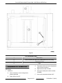
FULL SIZE GAS CONVECTION
OVEN
VC5GD
- NOTICE -
This Manual is prepared for the use of trained Hobart Service Technicians and should not
be used by those not properly qualified.
This manual is not intended to be all encompassing. If you have not attended a Hobart Service
School for this product, you should read, in its entirety, the repair procedure you wish to
perform to determine if you have the necessary tools, instruments and skills required to
perform the procedure. Procedures for which you do not have the necessary tools,
instruments and skills should be performed by a trained Hobart Service Technician.
The reproduction, transfer, sale or other use of this manual, without the express written
consent of Hobart, is prohibited.
This manual has been provided to you by ITW Food Equipment Group LLC ("ITW FEG")
without charge and remains the property of ITW FEG, and by accepting this manual you agree
that you will return it to ITW FEG promptly upon its request for such return at any time in the
future.
SERVICE MANUAL
A product of Vulcan-Hart 3600 North Point Blvd Baltimore, MD 21222
F45598 Rev. F (0323)

TABLE OF CONTENTS
SERVICE UPDATES ....................................................................................... 3
SERVICE UPDATES ................................................................................... 3
GENERAL .................................................................................................. 4
INTRODUCTION ....................................................................................... 4
OPERATION ........................................................................................... 4
INSTALLATION ........................................................................................ 4
LUBRICATION ......................................................................................... 4
CLEANING ............................................................................................. 4
SPECIFICATIONS ...................................................................................... 4
TOOLS ................................................................................................. 5
REMOVAL AND REPLACEMENT OF PARTS ............................................................... 6
COVERS AND PANELS ................................................................................ 6
CONTROL PANEL COMPONENTS ..................................................................... 7
COMPONENT PANEL COMPONENTS ................................................................. 8
TEMPERATURE PROBE ............................................................................... 8
GAS BURNER ......................................................................................... 9
GAS ORIFICE ......................................................................................... 10
GAS SOLENOID VALVE .............................................................................. 10
IGNITION CONTROL MODULE ....................................................................... 11
SPARK IGNITER AND FLAME SENSE ................................................................ 11
BLOWER ............................................................................................. 12
MOTOR ............................................................................................... 13
DOOR SWITCH ....................................................................................... 15
ROLLER LATCH ASSEMBLY (INDEPENDENT DOORS) ............................................... 16
DOOR REMOVAL ..................................................................................... 16
HIGH LIMIT THERMOSTAT ........................................................................... 19
INTERIOR LIGHTS .................................................................................... 19
COOLING FAN ........................................................................................ 20
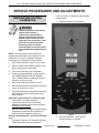
SERVICE PROCEDURES AND ADJUSTMENTS ........................................................... 21
TEMPERATURE CONTROL CALIBRATION ........................................................... 21
SOLID STATE TEMPERATURE CONTROL TEST ..................................................... 22
TEMPERATURE CONTROL BOARD FAULT INDICATOR .............................................. 22
TEMPERATURE PROBE TEST ....................................................................... 23
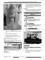
GAS VALVE PRESSURE CHECK ..................................................................... 23
VERIFICATION OF SPARK AT IGNITOR .............................................................. 24
BLOWER ADJUSTMENT .............................................................................. 25
DOOR STRIKE ADJUSTMENT INDEPENDENT DOORS) .............................................. 25
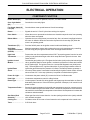
ELECTRICAL OPERATION ................................................................................ 27
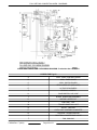
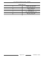
COMPONENT FUNCTION ............................................................................ 27
COMPONENT LOCATION ............................................................................. 28
SEQUENCE OF OPERATION ......................................................................... 33
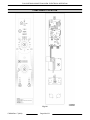
DIAGRAMS ............................................................................................... 36
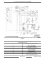
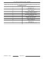
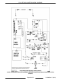
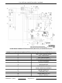
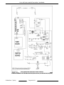
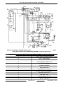
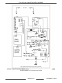
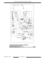
WIRING DIAGRAM AND SCHEMATIC ................................................................. 36
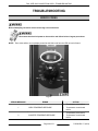
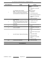
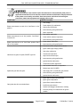
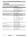
TROUBLESHOOTING ..................................................................................... 49
ERROR CODES ...................................................................................... 49
ALL MODELS ......................................................................................... 50
FULL SIZE GAS CONVECTION OVEN
© VULCAN 2023
F45598 Rev. F (0323) Page 2 of 52

SERVICE UPDATES
SERVICE UPDATES
March 2023
• Updated DOOR REMOVAL.
February 2022
• Updated BLOWER.
• Updated DOOR SWITCH.
• Updated INTERIOR LIGHTS.
• Updated WIRING DIAGRAM AND
SCHEMATIC.
April 2020
• Added new error code. ERROR CODES
December 2019
• Added ERROR CODES.
April 2018
• Updated WIRING DIAGRAM AND
SCHEMATIC.
FULL SIZE GAS CONVECTION OVEN - SERVICE UPDATES
Page 3 of 52 F45598 Rev. F (0323)

GENERAL
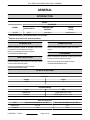
INTRODUCTION
Models
MODEL
FEATURES
CAVITY DEPTH TEMPERATURE
CONTROL
DOORS
(50/50)
VC5GD 26.5" Solid State Independent 1 2
1 Simultaneous doors are optional (with or w/o window).
2 Stainless steel doors with window (standard).
OPERATION
Refer to Operator's manual for operation instructions
(), located on Vulcan Resource Center.
https://my.vulcanfeg.com/resourcecenter/
vulcanwolfberkel/default.aspx
INSTALLATION
Detailed installation instructions (F31123) are located
on the Vulcan resource center.
https://my.vulcanfeg.com/resourcecenter/
vulcanwolfberkel/default.aspx
LUBRICATION
Refer to Lubrications Manual F20067 for current
values.
CLEANING
Refer to Operator's manual for cleaning instructions,
located on Vulcan Resource Center.
https://my.vulcanfeg.com/resourcecenter/
vulcanwolfberkel/default.aspx
SPECIFICATIONS
Electrical
Voltage Amps
120/60/1 8.0
Input BTU Rating
Fuel BTU
Natural Gas 50,000 input at 5 in. W.C.
Propane 50,000 input at 10.0 in. W.C.
Gas Line Pressures
Fuel Recommended Minimum (in. W.C.) Recommended Maximum (in. W.C.)
Natural Gas 8.0, 6.0 14.0
Propane 11.0 14.0
FULL SIZE GAS CONVECTION OVEN - GENERAL
F45598 Rev. F (0323) Page 4 of 52

TOOLS
Standard
• Standard set of Hand Tools.
• VOM with minimum of NFPA-70E CATIII 600V,
UL/CSA/TUV listed. Sensitivity of at least 20,000
ohms per volt and the ability to measure DC
micro amps. Meter leads must also be rated at
CAT III 600V.
• Clamp on type amp meter with minimum of
NFPA-70E CAT III 600V,UL/CSA/TUV listed.
Special
• Temperature Tester (Thermocouple Type).
• Manometer.
FULL SIZE GAS CONVECTION OVEN - GENERAL
Page 5 of 52 F45598 Rev. F (0323)

REMOVAL AND REPLACEMENT OF PARTS
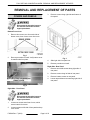
COVERS AND PANELS
Disconnect the electrical power to
the machine and follow lockout /
tagout procedures.
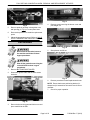
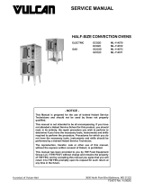
Bottom Front Cover
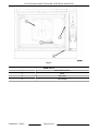
1. Remove four screws, two from each side of
bottom cover, then remove cover from oven.
Fig. 1
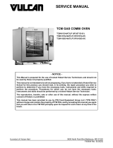
2. Reverse procedure to install. Verify bottom cover
is seated under front plate.
Fig. 2
Right Side - Front Panel
Disconnect the electrical power to
the machine and follow lockout /
tagout procedures.
1. Loosen two screws near front of oven, which
secure bottom front cover.
2. Loosen screws on left side of front panel and top
cover screw.
3. Remove screws along right side and bottom of
front panel.
Fig. 3
4. Slide right side front panel out.
5. Reverse procedure to install.
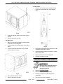
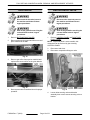
Right Side - Rear Panel
1. Remove two middle screws along right side of
rear panel.
2. Remove screws along left side of rear panel.
3. Remove bottom screws on rear panel.
4. Loosen top and bottom screw along right side of
rear panel.
FULL SIZE GAS CONVECTION OVEN - REMOVAL AND REPLACEMENT OF PARTS
F45598 Rev. F (0323) Page 6 of 52

Fig. 4
5. Slide right side rear panel up and to the right to
remove.
6. Reverse procedure to install.
Left Side Panel
1. Remove screws along right side, middle left side,
and bottom on left side panel.
2. Loosen screws on top and bottom on left side of
panel.
3. Loosen two screws near front of oven, which
secure bottom front cover.
Fig. 5
4. Lift up and pull away to remove.
5. Reverse procedure to install.
Control Panel
1. Remove three screws on the right side which
secure the control panel then lift up and pull
away.
Fig. 6
2. Disconnect the temperature probe leads from the
solid-state temperature control.
3. Unplug the wire harnesses connector to control
panel components.
4. Unplug Ground wire from control panel.
5. Reverse procedure to install.
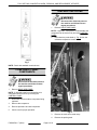
CONTROL PANEL COMPONENTS
Disconnect the electrical power to
the machine and follow lockout /
tagout procedures.
1. Remove CONTROL PANEL.
2. Remove component being replaced.
3. Reverse procedure to install replacement
component.
4. Check oven for proper operation.
FULL SIZE GAS CONVECTION OVEN - REMOVAL AND REPLACEMENT OF PARTS
Page 7 of 52 F45598 Rev. F (0323)

Fig. 7
NOTE: Panel with standard controls shown.
COMPONENT PANEL
COMPONENTS
Disconnect the electrical power to
the machine and follow lockout /
tagout procedures.
1. Remove RIGHT SIDE PANEL.
NOTE: If right side panel is not accessible, this
component can be service by removing the
CONTROL PANEL.
2. Disconnect the wire leads to component being
replaced.
3. Remove the component.
4. Reverse procedure to install component.
5. Check oven for proper operation.
TEMPERATURE PROBE
Disconnect the electrical power to
the machine and follow lockout /
tagout procedures.
1. Remove RIGHT SIDE PANEL.
NOTE: If right side - front panel is not accessible, this
component can be serviced by removing CONTROL
PANEL.
2. Disconnect the probe leads (1, Fig. 8) from the
solid state temperature control.
Fig. 8
3. Remove the racks from inside cavity.
4. Remove the probe guard.
FULL SIZE GAS CONVECTION OVEN - REMOVAL AND REPLACEMENT OF PARTS
F45598 Rev. F (0323) Page 8 of 52

Fig. 9
5. Remove probe by pushing it through the oven
wall opening (2, Fig. 8) in control panel area.
6. Reverse the procedure to install the replacement
probe.
7. Adjust the temperature control. Refer to: SOLID
STATE TEMPERATURE CONTROL TEST .
GAS BURNER
Disconnect the electrical power to
the machine and follow lockout /
tagout procedures.
Shut off the gas before servicing the
unit and follow lockout / tagout
procedures.
1. Remove BOTTOM FRONT COVER.
2. Disconnect ignition cable and the flame sense
lead wire.
Fig. 10
3. Remove bolts securing gas manifold to oven and
place manifold to the side.
Fig. 11
4. Remove screws securing the burner cover and
pull straight out.
Fig. 12
5. Grasp burner and lift out.
Fig. 13
6. Reverse procedure to install replacement burner.
NOTE: Ensure that burner positioning bracket (U-
shaped end) is inserted into slot at the rear of burner
chamber.
7. Check for proper operation.
FULL SIZE GAS CONVECTION OVEN - REMOVAL AND REPLACEMENT OF PARTS
Page 9 of 52 F45598 Rev. F (0323)

GAS ORIFICE
Disconnect the electrical power to
the machine and follow lockout /
tagout procedures.
Shut off the gas before servicing the
unit and follow lockout / tagout
procedures.
1. Remove BOTTOM FRONT COVER.
2. Remove bolts securing gas manifold to oven and
place manifold to the side.
Fig. 14
3. Remove gas orifice from spud on manifold and
replace with correct orifice for the given altitude.
Fig. 15
4. Reverse procedure to install and check for proper
operation.
GAS SOLENOID VALVE
Disconnect the electrical power to
the machine and follow lockout /
tagout procedures.
Shut off the gas before servicing the
unit and follow lockout / tagout
procedures.
1. Remove CONTROL PANEL and RIGHT SIDE
FRONT PANEL.
NOTE: if right side panel is not accessible, this
component can be serviced by just removing
CONTROL PANEL.
2. Disconnect lead wires.
3. Disconnect compression fittings to valve.
Fig. 16
4. Loosen bolts securing valve and bracket
assembly then remove screws securing valve to
bracket.
FULL SIZE GAS CONVECTION OVEN - REMOVAL AND REPLACEMENT OF PARTS
F45598 Rev. F (0323) Page 10 of 52

Fig. 17
5. Reverse procedure to install replacement gas
valve.
NOTE: Clean pipe threads and apply pipe joint
compound to threads. Any pipe joint compound used,
must be resistant to the action of propane gases.
All gas joints disturbed during servicing must be
checked for leaks. Check with a soap and water
solution (bubbles). Do not use an open flame.
6. Verify gas pressure as outlined under GAS
PRESSURE ADJUSTMENT.
7. Check for proper operation.
IGNITION CONTROL MODULE
Disconnect the electrical power to
the machine and follow lockout /
tagout procedures.
Shut off the gas before servicing the
unit and follow lockout / tagout
procedures.
1. Remove RIGHT SIDE FRONT PANEL.
NOTE: If right side panel is not accessible, this
component can be serviced by removing CONTROL
PANEL.
2. Disconnect lead wires (1, Fig. 18) and igniter
cable (2, Fig. 18) from ignition module board.
Fig. 18
3. Remove the ignition module board from the
mounting bracket.
4. Reverse the procedure to install replacement
ignition module board.
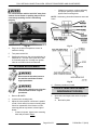
SPARK IGNITER AND FLAME
SENSE
Disconnect the electrical power to
the machine and follow lockout /
tagout procedures.
Shut off the gas before servicing the
unit and follow lockout / tagout
procedures.
1. Remove GAS BURNER.
2. Remove screws securing ignitor and flame sense
to burner, then remove assembly.
Fig. 19
FULL SIZE GAS CONVECTION OVEN - REMOVAL AND REPLACEMENT OF PARTS
Page 11 of 52 F45598 Rev. F (0323)

3. Reverse procedure to install assembly and check
for proper operation.
NOTE: Check to ensure spark gap distance is
approximately 1/8". If gap appears to be excessive or
poor sparking is occurring, then adjust.
Fig. 20
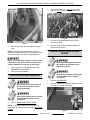
BLOWER
Disconnect the electrical power to
the machine and follow lockout /
tagout procedures.
Shut off the gas before servicing the
unit and follow lockout / tagout
procedures.
Removal
1. Remove racks.
2. Lay cardboard on bottom of oven cavity to protect
surface.
3. Remove snorkel (1, Fig. 21) and baffle panel (2,
Fig. 21) mounting screws.
Fig. 21
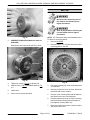
4. Loosen set screws on blower hub.
Fig. 22
5. Remove blower from motor shaft using a bearing
puller.
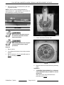
Installation
1. 1st GENERATION SHOWN IN Fig. 23 SN break
ends at 482010857 (Skip to Step 2 for current
production)
Slide blower onto motor shaft until hub is
protruding 1/8" (Fig. 23).
FULL SIZE GAS CONVECTION OVEN - REMOVAL AND REPLACEMENT OF PARTS
F45598 Rev. F (0323) Page 12 of 52

Fig. 23
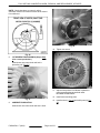
2. CURRENT PRODUCTION SN break starts at
482010858
Slide blower onto motor shaft until hub is flush.
Fig. 24
3. Tighten set screws ( Fig. 22) on blower hub.
4. Install snorkel (1, Fig. 21) and baffle panel (2, Fig.
21).
5. Install racks.
6. Check oven for proper operation.
MOTOR
Disconnect the electrical power to
the machine and follow lockout /
tagout procedures.
Shut off the gas before servicing the
unit and follow lockout / tagout
procedures.
NOTE: 1ST Generation motor is the Marathon motor.
Fir Motor is current production.
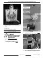
1. Remove BLOWER.
2. Remove bolts (1, Fig. 25) that secure the motor
mounting plate to rear wall.
Fig. 25
3. Pull motor assembly into oven cavity and place it
on cardboard.
4. Remove junction box cover on motor, disconnect
lead wires and remove conduit.
5. Remove motor mounting bolts and flat washers
then lift the motor from mounting plate.
6. Position replacement motor on motor mounting
plate and install mounting bolts and washers.
Hand tighten mounting bolts only.
7. Reconnect lead wires at motor, replace conduit
and junction box cover.
FULL SIZE GAS CONVECTION OVEN - REMOVAL AND REPLACEMENT OF PARTS
Page 13 of 52 F45598 Rev. F (0323)

NOTE: Check data plate on motor for wiring
schematic. Motor must rotate clockwise when viewed
from shaft end.
Fig. 26
8. 1ST GENERATION SHOWN IN (Skip to Step
9 for current production.)
Slide blower onto motor shaft until hub is
protruding 1/8" (Fig. 27).
Fig. 27
9. CURRENT PRODUCTION
Slide blower onto motor shaft until hub is flush.
Fig. 28
10. Tighten set screws.
11. Adjust motor position until blower is parallel to
motor mounting plate as outlined under
BLOWER ADJUSTMENT.
12. Install motor mounting plate.
13. Install snorkel (1, Fig. 30) and baffle panel (2, Fig.
30).
FULL SIZE GAS CONVECTION OVEN - REMOVAL AND REPLACEMENT OF PARTS
F45598 Rev. F (0323) Page 14 of 52

Fig. 30
14. Remove cardboard from the bottom of the oven
cavity.
15. Install racks.
16. Check oven for proper operation.
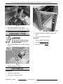
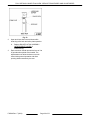
DOOR SWITCH
Disconnect the electrical power to
the machine and follow lockout /
tagout procedures.
1. Remove BOTTOM FRONT COVER.
2. Remove door switch mounting hardware.
1st GENERATION SHOWN IN Fig. 31
Fig. 31
CURRENT PRODUCTION SHOWN IN Fig. 32
Fig. 32
3. Pull door switch and washer out through bottom
panel opening.
FULL SIZE GAS CONVECTION OVEN - REMOVAL AND REPLACEMENT OF PARTS
Page 15 of 52 F45598 Rev. F (0323)

Fig. 33
4. Disconnect lead wires to door switch.
5. Reverse procedure to install replacement switch.
ROLLER LATCH ASSEMBLY
(INDEPENDENT DOORS)
Disconnect the electrical power to
the machine and follow lockout /
tagout procedures.
1. Remove screws that attach roller latch assembly
to door.
Fig. 34
2. Reverse procedure to install.
DOOR REMOVAL
Left Side Door
1. Open door to a 90° angle.
2. Lift door up off hinges to remove.
Fig. 35
3. Reverse procedure to install the replacement
door.
4. Check oven for proper operation.
Right Side
1. Remove RIGHT SIDE PANEL.
2. Remove CONTROL PANEL.
3. Remove panel trim (Fig. 36).
FULL SIZE GAS CONVECTION OVEN - REMOVAL AND REPLACEMENT OF PARTS
F45598 Rev. F (0323) Page 16 of 52

Fig. 36
4. Remove two component panel mounting screws
(Fig. 37).
Fig. 37
5. Remove two fan conduit plate mounting screws
(Fig. 38).
Fig. 38
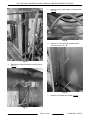
6. Remove four front and rear insulation panel
mounting screws (Fig. 39).
Fig. 39
7. Remove door switch wire conduit (Fig. 40).
FULL SIZE GAS CONVECTION OVEN - REMOVAL AND REPLACEMENT OF PARTS
Page 17 of 52 F45598 Rev. F (0323)

Fig. 40
8. Pull conduit (1, Fig. 41) back out of way.
Fig. 41
9. Remove five front right side insulation panel
screws (Fig. 42).
Fig. 42
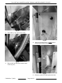
10. Slide front insulation panel (1, Fig. 43) back to
access hinge screws to remove hinge.
Fig. 43
11. Reverse procedure to install replacement door.
FULL SIZE GAS CONVECTION OVEN - REMOVAL AND REPLACEMENT OF PARTS
F45598 Rev. F (0323) Page 18 of 52

12. Check oven for proper operation.
HIGH LIMIT THERMOSTAT
Disconnect the electrical power to
the machine and follow lockout /
tagout procedures.
1. Remove racks.
2. Remove high limit thermostat cover/mounting
plate from inside oven cavity at the top.
Fig. 44
3. Disconnect lead wires from high limit thermostat.
NOTE: Remove old RTV sealer from cover and
mating surfaces inside oven cavity and apply new high
temperature RTV sealer before installing.
4. Reverse procedure to install.
INTERIOR LIGHTS
Disconnect the electrical power to
the machine and follow lockout /
tagout procedures.
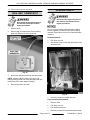
Do not touch the Halogen lamp with bare hands. If
lamp is exposed to oil from the skin, the life will be
reduced. Ensure lamp is free from oil and dirt before
replacing.
Bulb Replacement
1. Pull lamp cover off.
2. Grasp lamp using a clean cloth and remove from
lamp assembly.
Fig. 45
3. Reverse procedure to install new bulb.
Lamp Assembly Replacement
1. Remove racks.
2. Pull lamp cover off.
3. Pull lamp assembly out.
4. Reverse procedure to install new lamp assembly.
FULL SIZE GAS CONVECTION OVEN - REMOVAL AND REPLACEMENT OF PARTS
Page 19 of 52 F45598 Rev. F (0323)

COOLING FAN
Disconnect the electrical power to
the machine and follow lockout /
tagout procedures.
1. Remove RIGHT SIDE FRONT PANEL.
NOTE: If right side - front panel is not accessible, this
component can be serviced by removing CONTROL
PANEL.
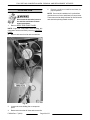
2. Remove wire nuts from fan wire connections.
Fig. 46
3. Loosen tab screw holding fan to component
panel.
4. Rotate tab so that fan will clear and remove fan.
5. Reverse procedure to install fan and check for
proper operation.
NOTE: Fan must be installed so air is pulled from
outside the rear of oven and blown into control area.
The arrow on the fan body indicates "air flow" direction
and should be pointing toward controls.
FULL SIZE GAS CONVECTION OVEN - REMOVAL AND REPLACEMENT OF PARTS
F45598 Rev. F (0323) Page 20 of 52
Page is loading ...
Page is loading ...
Page is loading ...
Page is loading ...
Page is loading ...
Page is loading ...
Page is loading ...
Page is loading ...
Page is loading ...
Page is loading ...
Page is loading ...
Page is loading ...
Page is loading ...
Page is loading ...
Page is loading ...
Page is loading ...
Page is loading ...
Page is loading ...
Page is loading ...
Page is loading ...
Page is loading ...
Page is loading ...
Page is loading ...
Page is loading ...
Page is loading ...
Page is loading ...
Page is loading ...
Page is loading ...
Page is loading ...
Page is loading ...
Page is loading ...
Page is loading ...
-
 1
1
-
 2
2
-
 3
3
-
 4
4
-
 5
5
-
 6
6
-
 7
7
-
 8
8
-
 9
9
-
 10
10
-
 11
11
-
 12
12
-
 13
13
-
 14
14
-
 15
15
-
 16
16
-
 17
17
-
 18
18
-
 19
19
-
 20
20
-
 21
21
-
 22
22
-
 23
23
-
 24
24
-
 25
25
-
 26
26
-
 27
27
-
 28
28
-
 29
29
-
 30
30
-
 31
31
-
 32
32
-
 33
33
-
 34
34
-
 35
35
-
 36
36
-
 37
37
-
 38
38
-
 39
39
-
 40
40
-
 41
41
-
 42
42
-
 43
43
-
 44
44
-
 45
45
-
 46
46
-
 47
47
-
 48
48
-
 49
49
-
 50
50
-
 51
51
-
 52
52


VULCAN & WOLF VC5GD Full Size Gas Convection Oven User manual
- Type
- User manual
Ask a question and I''ll find the answer in the document
Finding information in a document is now easier with AI
Related papers
-
 VULCAN & WOLF VC5ED Full Size Electric Convection Oven User manual
-
 VULCAN & WOLF SG4 SG6 Oven User manual
-
 VULCAN & WOLF ECO2, GCO2 Half-Size Convection Ovens User manual
-
 VULCAN & WOLF TCM Gas Combi Oven User manual
-
 VULCAN & WOLF SX Series Value Range User manual
-
 VULCAN & WOLF Mini Jet Combi Oven User manual
-
 VULCAN & WOLF C24EA Steamer User manual
-
 VULCAN & WOLF EV Range User manual
-
 VULCAN & WOLF Daily Operating instructions
-
 VULCAN & WOLF VHU18 Series Proofer Cab User manual


