VCS Series Multifunction Cooker
Heavy Duty Range
VCS18 ML-137003-000
18
VCS36 ML-137003-000
36
VCS36D ML-137003-003
6D
- NOTICE -
This Manual is prepared for the use of trained Hobart Service Technicians and should not
be used by those not properly qualified.
This manual is not intended to be all encompassing. If you have not attended a Hobart Service
School for this product, you should read, in its entirety, the repair procedure you wish to
perform to determine if you have the necessary tools, instruments and skills required to
perform the procedure. Procedures for which you do not have the necessary tools,
instruments and skills should be performed by a trained Hobart Service Technician.
The reproduction, transfer, sale or other use of this manual, without the express written
consent of Hobart, is prohibited.
This manual has been provided to you by ITW Food Equipment Group LLC ("ITW FEG")
without charge and remains the property of ITW FEG, and by accepting this manual you agree
that you will return it to ITW FEG promptly upon its request for such return at any time in the
future.
SERVICE MANUAL
A product of Vulcan-Hart 3600 North Point Blvd Baltimore, MD 21222
F45718 Rev. C (0223)

TABLE OF CONTENTS
SERVICES UPDATES ...................................................................................... 3
SERVICE UPDATES ................................................................................... 3
TIS DOCUMENT LIST - VCS SERIES MULTIFUNCTION COOKER ...................................... 3
GENERAL .................................................................................................. 4
INTRODUCTION ....................................................................................... 4
INSTALLATION, OPERATION AND CLEANING ......................................................... 4
TOOLS ................................................................................................. 4
SPECIFICATIONS ...................................................................................... 4
REMOVAL AND REPLACEMENT OF PARTS ............................................................... 6
COVERS AND PANELS ................................................................................ 6
FACIA (DISPLAY) BOARD .............................................................................. 8
WATER FILL BUTTON ................................................................................. 8
CONTACTOR AND RELAY BOARD .................................................................... 9
DATA CABLE .......................................................................................... 9
FUSES AND POWER SUPPLY CONNECTION ........................................................ 10
COOLING FAN & SOLENOID VALVE .................................................................. 10
HEATING ELEMENT REPLACEMENT ................................................................. 11
INTERIOR ACCESS TO HEATING ELEMENT (PREFERRED METHOD) ............................... 12
TANK REMOVAL ...................................................................................... 13
IN-TANK TEMPERATURE PROBE .................................................................... 14
SERVICE PROCEDURES AND ADJUSTMENTS ........................................................... 18
CHECKING TEMPERATURE PROBES ................................................................ 18
HEATING ELEMENT RESISTANCE ................................................................... 20
ELECTRICAL OPERATION ................................................................................ 21
SEQUENCE OF OPERATION ......................................................................... 21
WIRING DIAGRAM .................................................................................... 22
COMPONENT LOCATION ............................................................................. 23
CONTROL PANEL .................................................................................... 24
FACIA (DISPLAY) BOARD ............................................................................ 25
RELAY BOARD ....................................................................................... 26
SOFTWARE .............................................................................................. 27
CHECKING SOFTWARE VERSION ................................................................... 27
UPDATING SOFTWARE .............................................................................. 27
DATA LOGGERS ..................................................................................... 28
CONFIGURE FAHRENHEIT/ CELSIUS DISPLAY ...................................................... 29
TROUBLESHOOTING ..................................................................................... 31
TROUBLESHOOTING CHART ........................................................................ 31
ERROR CODES ...................................................................................... 33
VCS Series Multifunction Cooker Heavy Duty Range
© VULCAN 2023
F45718 Rev. C (0223) Page 2 of 35

SERVICES UPDATES
SERVICE UPDATES
November 2021
• Added IN-TANK TEMPERATURE PROBE.
January 2021
• Added CONFIGURE FAHRENHEIT/ CELSIUS
DISPLAY.
• Updated ERROR CODES.
• Updated TROUBLESHOOTING CHART.
November, 2018
• Added TIS Document List.
TIS DOCUMENT LIST - VCS Series Multifunction Cooker
SERVICE TAB
Document Title Document Type
VCS Series Multifunction Cooker Heavy Duty Range
Service Manual Service Manual
SERVICE TAB (Multimedia)
Document Title Document Type
Repair Flood-Damaged Equipment Misc
VCS Series Multifunction Cooker Installation and Operation Operator
VCS Multifunction Cooker Specifications Specification Sheet
Rating Plate Locations on Current Vulcan-Hart Technical Service Bulletin (TSB)
TSB 1037A Hobart to Vulcan "Common" Model Cross Reference List Technical Service Bulletin (TSB)
PARTS TAB
Document Title Document Type
VCS Series Multifunction Cooker Heavy Duty Range
Parts Catalog Parts Catalog
VCS Series Multifunction Cooker Heavy Duty Range - SERVICES UPDATES
Page 3 of 35 F45718 Rev. C (0223)

GENERAL
INTRODUCTION
This manual is applicable only to models listed on the cover page. Procedures in this manual will apply to all models
unless specified. Pictures and illustrations can be of any model unless they need to be model specific.
INSTALLATION, OPERATION AND CLEANING
For detailed installation, operation and cleaning instructions, refer to VCS Multifunction Cooker Installation and
Operation Manual. The manual is also available online at www.vulcanequipment.com.
TOOLS
Standard
• Standard set of hand tools.
• Metric set of hand tools.
• VOM with measuring micro amp current tester. Any VOM with minimum of CAT III 600V, CE certified. Sensitivity
of at least 20,000 ohms per volt can be used. In addition, meter leads must also be a minimum of CAT III 600V.
• Clamp on type amp meter with minimum of NFPA-70E CAT III 600V, UL/CSA/TUV listed.
• Temperature tester (thermocouple type).
• Field service grounding kit.
• Torque wrench with 3.7 ft. lbs (5 Nm) capacity.
• High temperature silicone caulk.
SPECIFICATIONS
Refer to VCS Multifunction Cooker Specifications
Electrical
MODEL DESCRIPTION VOLTAGE TOTAL KW KW PER PHASE AMPS PER LINE WIRE
X-Y Y-Z X-Z X Y Z
VCS18
18" Wide /
Single Tank
(front to back) 208 / 240V
9.0
3000 3000 3000 25 25 25
VCS36
36" Wide /
Single Tank
(left to right)
9.0
VCS Series Multifunction Cooker Heavy Duty Range - GENERAL
F45718 Rev. C (0223) Page 4 of 35

Electrical
MODEL DESCRIPTION VOLTAGE TOTAL KW KW PER PHASE AMPS PER LINE WIRE
X-Y Y-Z X-Z X Y Z
VCS36
D
36" Wide /
Double Tank
(front to back)
208 / 240V LH Tank -
9.0 3000 3000 3000 25 25 25
208 / 240V RH Tank -
9.0 3000 3000 3000 25 25 25
Water
• Cold water only.
• Pressure between 60-80psi.
VCS Series Multifunction Cooker Heavy Duty Range - GENERAL
Page 5 of 35 F45718 Rev. C (0223)

REMOVAL AND REPLACEMENT OF PARTS
COVERS AND PANELS
Disconnect the electrical power to
the machine and follow lockout /
tagout procedures.
Control Panel
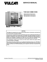
1. Open lower cabinet door.
2. Remove side (1), top (2) and inner (3) mounting
screws (Fig. 1).
Fig. 1
3. Disconnect wiring to remove control panel.
4. Reverse procedure to install.
Inside Splash Cover
1. Lift tabs out of slot in front of inside splash cover.
Fig. 2
2. Tilt to release and lift out of slots to remove.
3. Reverse procedure to install.
Lower Access Panel (Fuses, Terminal Block)
1. Open lower cabinet door.
2. Remove drain tube (1, Fig. 3) by turning to align
tabs (2, Fig. 3) with slots. Tube will drop free.
Fig. 3
3. Remove INSIDE SPLASH COVER.
4. Remove screws to lower access panel.
Fig. 4
5. Grasp bottom edge of panel, lift up to clear lip and
tilt forward to remove.
Fig. 5
VCS Series Multifunction Cooker Heavy Duty Range - REMOVAL AND REPLACEMENT OF PARTS
F45718 Rev. C (0223) Page 6 of 35

6. Reverse procedure to install.
Upper Access Panel (Contactor, Relay Board)
1. Open lower cabinet door.
2. Remove drain tube (1, Fig. 6) by turning to align
tabs (2, Fig. 6) with slots. Tube will drop free.
Fig. 6
3. Remove INSIDE SPLASH COVER.
4. Remove screws from upper access panel (1, Fig.
7).
Fig. 7
5. Lift from bottom and tilt forward to remove panel.
6. Reverse procedure to install.
Back Panel Access
1. Remove right and left side trim covers (1, Fig.
8).
Fig. 8
2. Remove right and left side riser brackets (2, Fig.
8).
3. Remove back panel mounting screws.
VCS Series Multifunction Cooker Heavy Duty Range - REMOVAL AND REPLACEMENT OF PARTS
Page 7 of 35 F45718 Rev. C (0223)

Fig. 9
4. Lift panel up and off unit.
5. Reverse procedure to install.
Reseal top edge with high temperature silicone before
replacing brackets.
FACIA (DISPLAY) BOARD
Disconnect the electrical power to
the machine and follow lockout /
tagout procedures.
1. Remove CONTROL PANEL.
2. Press release tab and pull down to disconnect
the RJ45 data cable from facia board (1, Fig.
10).
Fig. 10
3. Pull connector plug (2, Fig. 10) straight back to
disconnect selector switch (3, Fig. 10) from Facia
Board.
4. Pull plug (4, Fig. 10) up and slightly sideways to
disengage potentiometer (5, Fig. 10) retention
clip.
5. Remove facia board lock nuts to release.
6. Reverse procedure to install.
7. Verify operation.
WATER FILL BUTTON
Disconnect the electrical power to
the machine and follow lockout /
tagout procedures.
1. Remove CONTROL PANEL.
2. Disconnect water fill button (1, Fig. 11) control
wires.
Fig. 11
3. Remove water fill button from control panel.
A. Remove plastic nut.
VCS Series Multifunction Cooker Heavy Duty Range - REMOVAL AND REPLACEMENT OF PARTS
F45718 Rev. C (0223) Page 8 of 35

Retain rubber O-ring.
B. Remove button from the front of control
panel.
4. Reverse procedure to install.
Verify rubber O-ring is in place to keep moisture out.
5. Verify operation
CONTACTOR AND RELAY BOARD
Disconnect the electrical power to
the machine and follow lockout /
tagout procedures.
1. Remove UPPER ACCESS PANEL.
2. Remove retention screw (3, Fig. 12) to
disconnect enclosure from support brackets.
Fig. 12
3. Pull enclosure forward to disconnect or test
contactor (1, Fig. 12) and or relay board (2, Fig.
12).
If disconnecting relay board, do not disconnect wire
connections at the board. Instead, unplug wires from
heating elements and fuse block to remove entire
assembly. Replacement relay boards will include wire
harnesses already attached.
NOTE: If relay board needs to be removed from
enclosure do Step 4.
4. Disconnect heat sink (4, Fig. 12) attached to
radiator bar on outside of enclosure, by removing
three screws and lock nuts.
5. Reverse procedure to install
6. Verify operation.
DATA CABLE
Disconnect the electrical power to
the machine and follow lockout /
tagout procedures.
The RJ45 fiber optic patch, high temperature data
cable can be damaged by pinching, tight bending, and
excessive heat. In all of these cases, communication
will be lost between the relay and facia boards,
resulting in the unit not operating. Refer to
TROUBLESHOOTING CHART for symptoms.
1. Remove CONTROL PANEL.
2. Remove UPPER ACCESS PANEL.
3. Remove data cable heat shield mounting screws.
Fig. 13
4. Unplug data cable from facia board and relay
board.
5. Remove data cable from unit.
VCS Series Multifunction Cooker Heavy Duty Range - REMOVAL AND REPLACEMENT OF PARTS
Page 9 of 35 F45718 Rev. C (0223)

6. Route new data cable through forward bulkhead
bushing, down left hand raceway, and left hand
interior cable bushings into relay board
enclosure.
Fig. 14
7. Leave enough length of cable protruding from
forward bulkhead bushing to maneuver control
panel. Pull excess data cable into relay board
enclosure.
8. Plug data cable into relay board and facia board.
9. Verify proper operation of unit.
10. Replace covers.
11. Verify proper operation of unit.
FUSES AND POWER SUPPLY
CONNECTION
Disconnect the electrical power to
the machine and follow lockout /
tagout procedures.
1. Remove LOWER ACCESS PANEL.
2. Fuses (1, Fig. 15) and power supply connection
(2, Fig. 15) is located under the lower access
panel.
Fig. 15
3. Disconnect fuses to replace.
4. Reverse procedure to install.
5. Verify operation.
COOLING FAN & SOLENOID VALVE
Disconnect the electrical power to
the machine and follow lockout /
tagout procedures.
1. Remove BACK PANEL.
2. Cooling fan and solenoid are both accessible
with back panel removed.
NOTE: If back of unit is not accessible, fan and
solenoid can be accessed from the front by first
moving CONTACTOR AND RELAY BOARD
ENCLOSURE forward and out of the way.
VCS Series Multifunction Cooker Heavy Duty Range - REMOVAL AND REPLACEMENT OF PARTS
F45718 Rev. C (0223) Page 10 of 35

HEATING ELEMENT
REPLACEMENT
Disconnect the electrical power to
the machine and follow lockout /
tagout procedures.
1. Access heating elements.
There are two methods to access heating elements.
Interior access is the preferred method. In certain
circumstances, it may be necessary to access the
heating elements by removing the entire tank
assembly, either because of a catastrophic failure of
the material or inaccessibility through normal means.
• INTERIOR ACCESS TO HEATING
ELEMENT (PREFERRED METHOD)
• EXTERIOR ACCESS - TANK REMOVAL
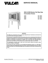
Change Heating Element
1. Disconnect power wires from porcelain block (1,
Fig. 17).
Fig. 17
The printed heating elements rely on perfect contact
across their entire surface to operate. It is vital to use
proper torque on all hardware and replace the graphite
pad and mica washers whenever an element is
removed. Rapid failure of the element will result if this
is not done.
2. Remove porcelain block (1, Fig. 17) by removing
two nuts and lowering entire block. Be careful to
retain tension spring from thermocouple.
3. Remove heating element.
A. Remove eight nuts.
B. Remove four steel washers.
C. Remove four mica washers (2, Fig. 17).
Discard and replace with new.
D. Remove graphite pad (3, Fig. 17). Discard
and replace with new.
4. Reverse procedure to install. Torque all nuts to
3.7 ft-lb (5 Nm).
VCS Series Multifunction Cooker Heavy Duty Range - REMOVAL AND REPLACEMENT OF PARTS
Page 11 of 35 F45718 Rev. C (0223)

Verify graphite pad is flat and element has complete
contact across entire surface.
Verify thermocouple is seated and held firmly against
tank bottom by spring. If not, error code ESx will result
(Refer to ERROR CODES).
Heating elements are position sensitive and must be
hooked up in order. Power supply wires and
temperature probes are marked for the element they
belong to and must correspond or unit will not function
and error codes will appear on display. Element
positions are as noted in Fig. 18.
Fig. 18
INTERIOR ACCESS TO HEATING
ELEMENT (PREFERRED METHOD)
Disconnect the electrical power to
the machine and follow lockout /
tagout procedures.
There are two methods to access heating elements,
INTERIOR ACCESS and TANK REMOVAL.
INTERIOR ACCESS is the preferred method. In
certain circumstances, it may be necessary to access
the heating elements by removing the entire tank
assembly, either because of a catastrophic failure of
the material or inaccessibility through normal means.
Interior Access to Heating Element (Preferred
Method)
1. Remove drain tube (1, Fig. 19) by turning to align
tabs (2, Fig. 19) with slots. Tube will drop free.
Fig. 19
2. Remove splash cover mounting screws (1, Fig.
20). Slide cover forward to remove.
Fig. 20
3. Refer to HEATING ELEMENT RESISTANCE or
HEATING ELEMENT REPLACEMENT.
VCS Series Multifunction Cooker Heavy Duty Range - REMOVAL AND REPLACEMENT OF PARTS
F45718 Rev. C (0223) Page 12 of 35

TANK REMOVAL
Disconnect the electrical power to
the machine and follow lockout /
tagout procedures.
In certain circumstances, it may be necessary to
remove or change the entire tank assembly, either
because of a catastrophic failure of the material or
inaccessibility through normal means. In this case, the
following steps must be followed to ensure proper
operation and to avoid damage of components.
To prevent water incursion into electronics, entire top
frame is sealed at the factory with high temperature
silicone caulk. This seal must be broken before tank
can be removed.
1. Remove CONTROL PANEL, UPPER ACCESS
PANEL, and LOWER ACCESS PANEL.
2. Mark and disconnect hi-limit wires.
Fig. 21
3. Remove retention screws under front ledge.
Fig. 22
4. Remove riser and spigot bracket, if accessible.
NOTE: Hose does not need to be disconnected.
Fig. 23
5. Break top frame seal by running a utility knife or
other short blade through all seams.
6. Lift tank and top frame straight up off unit frame.
Wiring has enough slack to allow tank to be lifted and
turned over onto an adjacent surface. Use care to
ensure no snags occur, especially with thermocouple
wires as damage can cause unit to fail to operate.
Bottom of tank can now be freely accessed to assess
heating elements and wiring.
Fig. 24
VCS Series Multifunction Cooker Heavy Duty Range - REMOVAL AND REPLACEMENT OF PARTS
Page 13 of 35 F45718 Rev. C (0223)

Heating elements are position sensitive and must be
hooked up in order. Power supply wires and
temperature probes are marked for the element they
belong to and must correspond or unit will not function
and error codes will appear on display. Element
positions are as noted in Fig. 25.
Fig. 25
7. Reverse procedure to install.
If replacing tank assembly:
A. Disconnect wiring, nuts and break seal to lift
tank from top frame.
B. Install new tank with (15) 1/4-20 lock nuts.
C. Seal tank to top frame with high temperature
silicone sealant.
It is critical that all seams are resealed with high
temperature silicone. Failure to do so will result in
water incursion into electronics and failure of unit.
IN-TANK TEMPERATURE PROBE
Disconnect the electrical power to
the machine and follow lockout /
tagout procedures.
NOTE: Temperature probe kit will be needed for
replacement which includes temperature probe, two
silicone washer and M5 nut.
Removal
1. Open door.
2. Remove CONTROL PANEL.
3. Remove UPPER ACCESS PANEL.
4. Note and disconnect temperature probe wiring
(1, Fig. 26) from relay board.
Fig. 26
5. Pull probe wiring through grommet.
VCS Series Multifunction Cooker Heavy Duty Range - REMOVAL AND REPLACEMENT OF PARTS
F45718 Rev. C (0223) Page 14 of 35

Fig. 27
6. Remove brass probe mounting nut (1, Fig. 28).
NOTE: 8 MM wrench needed.
NOTE: Probe located straight up on outside of tank.
Fig. 28
7. Remove temperature probe from flange.
Installation
1. Align silicone washer (1, Fig. 29) on each side of
temperature probe (2, Fig. 29).
VCS Series Multifunction Cooker Heavy Duty Range - REMOVAL AND REPLACEMENT OF PARTS
Page 15 of 35 F45718 Rev. C (0223)

Fig. 29
2. Insert probe into flange against tank.
A. Tighten first brass nut (1, Fig. 30) (8 MM
wrench).
B. Perform leak test.
1) Fill tank just above probe location.
2) Lay a paper towel inside unit.
Verify no drips on paper towel or leaks around brass
nut.
Fig. 30
3. Tighten second brass nut to lock in place.
4. Route wiring through grommet.
VCS Series Multifunction Cooker Heavy Duty Range - REMOVAL AND REPLACEMENT OF PARTS
F45718 Rev. C (0223) Page 16 of 35


SERVICE PROCEDURES AND ADJUSTMENTS
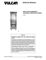
CHECKING TEMPERATURE PROBES
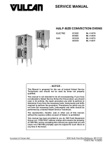
Temperature probes are resistance sensors with the value of 100 ohms for a temperature of 0°F and 138.5 ohms
for a temperature of 212°F. The variation of the resistance to temperature relationship is linear. The resistance
reading is directly proportional to the measured temperature. The sensor is not polarized. The sensor can be
extended using copper wire.
How to Read the Chart (Example) -
To find the resistance corresponding to a temperature of 372°F.
• Find row corresponding to 370°F and column corresponding to 2.
The intersection shows resistance of 171.76 Ohms.
Check Resistance
Disconnect the electrical power to the machine and follow lockout / tagout procedures.
1. Check resistance with an ohmmeter set to 200 ohms (less than 107 ohms for 68°F).
2. Check insulation between one of the leads and the metal part with ohmmeter set at 20 mega ohms (a value
over 15 mega ohms).
3. Check continuity between the feed and the metal part of sensor. Refer to chart below for readings (CHECKING
TEMPERATURE PROBES).
Fig. 33
Temperature in °F relative to Resistance in Ohms for PT100 sensor
°F 0 1 2 3 4 5 6 7 8 9 10
50 103.90 104.12 104.34 104.55 104.77 104.98 105.20 105.42 105.36 105.85 106.07
60 106.07 106.28 106.50 106.71 106.93 107.15 107.36 107.58 107.79 108.01 108.23
70 108.23 108.44 108.66 108.87 109.09 109.30 109.52 109.73 109.95 110.17 110.38
80 110.38 110.60 110.81 111.03 111.24 111.46 111.67 111.89 112.10 112.32 112.53
90 112.53 112.75 112.96 113.18 113.39 113.61 113.82 114.04 114.25 114.47 114.68
100 114.68 114.90 115.11 115.33 115.54 115.76 115.97 116.18 116.40 116.61 116.83
VCS Series Multifunction Cooker Heavy Duty Range - SERVICE PROCEDURES AND ADJUSTMENTS
F45718 Rev. C (0223) Page 18 of 35

Temperature in °F relative to Resistance in Ohms for PT100 sensor
°F 0 1 2 3 4 5 6 7 8 9 10
110 116.83 117.04 117.26 117.68 117.68 117.68 118.11 118.33 118.54 118.76 118.97
120 118.97 119.18 119.40 119.61 119.82 120.04 120.25 120.47 120.68 120.89 121.11
130 121.11 121.32 121.53 121.75 121.96 122.18 122.39 122.60 122.82 123.03 123.24
140 123.24 123.67 123.67 123.88 124.09 124.31 124.52 124.73 124.95 125.16 125.37
150 125.37 125.59 125.80 126.01 126.22 126.44 126.65 126.86 127.08 127.29 127.50
160 127.50 127.71 127.93 128.14 128.35 128.56 128.78 128.99 129.20 129.41 129.62
170 129.62 129.84 130.05 130.26 130.47 130.68 130.90 131.11 131.32 131.53 131.74
180 131.74 131.96 132.17 132.38 132.59 132.80 133.01 133.23 133.44 133.65 133.86
190 133.86 134.07 134.28 134.50 134.71 134.92 135.13 135.34 135.55 135.76 135.97
200 135.97 136.19 136.40 136.61 136.82 137.03 137.24 137.45 137.66 137.87 138.08
210 138.08 138.29 138.51 138.72 139.14 139.14 139.35 139.56 139.77 139.98 140.19
220 140.19 140.40 140.61 140.82 141.03 141.24 141.45 141.66 141.87 142.08 142.29
230 142.29 142.50 142.71 142.92 143.13 143.34 143.55 143.76 143.97 144.18 144.39
240 144.39 144.60 144.81 145.02 145.44 145.44 145.65 145.86 146.07 146.28 146.49
250 146.49 146.70 146.91 147.11 147.32 147.53 147.74 147.95 148.16 148.37 148.58
260 148.58 148.79 149.00 149.21 147.32 149.41 149.83 150.04 150.25 150.46 150.67
270 150.67 150.88 151.08 151.29 151.50 151.71 151.92 152.13 152.33 152.54 152.75
280 152.75 152.96 153.17 153.38 153.58 153.79 154.00 154.21 154.42 154.62 154.83
290 154.83 155.04 155.25 155.46 155.66 155.87 156.08 156.29 156.49 156.70 156.91
300 156.91 157.12 157.33 157.53 157.74 157.95 158.15 158.36 158.57 158.78 158.98
310 158.98 159.19 159.40 159.61 159.81 160.02 160.23 160.43 160.64 160.85 161.05
320 161.05 161.26 161.47 161.67 161.88 160.09 162.29 162.50 162.71 162.91 163.12
330 163.12 163.33 163.53 163.74 163.95 164.15 164.36 164.57 164.77 164.98 165.18
340 163.18 165.39 165.60 165.80 166.01 166.21 166.42 166.63 166.83 167.04 167.24
350 167.24 167.45 167.66 167.86 168.07 168.27 168.48 168.68 168.89 169.09 169.30
360 169.30 169.51 169.71 169.92 170.12 170.33 170.53 170.74 170.94 171.15 171.35
370 171.35 171.76 171.76 171.97 172.17 172.38 172.58 172.79 172.99 173.20 173.40
380 173.40 173.61 173.81 174.02 174.22 174.43 174.63 174.83 175.04 175.24 175.45
390 175.45 175.65 175.86 196.06 176.26 176.47 176.67 176.88 177.08 177.29 177.49
400 177.49 177.69 177.90 178.10 178.30 178.51 178.71 178.92 179.12 179.32 179.53
410 179.53 179.73 179.93 180.14 180.34 180.55 180.75 180.95 181.16 181.36 181.56
420 181.56 181.77 181.97 182.17 182.38 182.58 182.78 182.98 183.19 183.39 183.59
430 183.59 183.80 184.00 184.20 184.40 184.61 184.81 185.01 185.22 185.42 185.62
440 185.62 185.82 186.03 186.23 186.43 186.63 186.84 187.04 187.24 187.44 187.65
450 187.65 187.85 188.05 188.25 188.45 188.66 188.86 189.06 189.26 189.46 189.67
VCS Series Multifunction Cooker Heavy Duty Range - SERVICE PROCEDURES AND ADJUSTMENTS
Page 19 of 35 F45718 Rev. C (0223)

HEATING ELEMENT RESISTANCE
Disconnect the electrical power to
the machine and follow lockout /
tagout procedures.
Resistance cannot be checked at the relay board due
to wire routing. Readings will not be correct.
1. Access heating elements.
There are two methods to access heating elements.
Interior access is the preferred method. In certain
circumstances, it may be necessary to access the
heating elements by removing the entire tank
assembly, either because of a catastrophic failure of
the material or inaccessibility through normal means.
• INTERIOR ACCESS TO HEATING
ELEMENT (PREFERRED METHOD)
• TANK REMOVAL
2. Check resistance directly at terminals on
porcelain block after removing wires as shown in
Fig. 34.
Fig. 34
NOTE: Depending on the manufacturer, element
resistance will either be 27 - 29 ohms, or 35 - 37 ohms.
Heating elements are position sensitive and must be
hooked up in order. Power supply wires and
temperature probes are marked for the element they
belong to and must correspond or unit will not function
and error codes will appear on display. Element
positions are as noted in Fig. 35.
Fig. 35
VCS Series Multifunction Cooker Heavy Duty Range - SERVICE PROCEDURES AND ADJUSTMENTS
F45718 Rev. C (0223) Page 20 of 35
Page is loading ...
Page is loading ...
Page is loading ...
Page is loading ...
Page is loading ...
Page is loading ...
Page is loading ...
Page is loading ...
Page is loading ...
Page is loading ...
Page is loading ...
Page is loading ...
Page is loading ...
Page is loading ...
Page is loading ...
/