Page is loading ...

3. Feed the power supply wires through the center hole and secure backplate to the junction box with screws
provided.
4. Electrical connections should be made inside junction box
as follows.
White - Common/Neutral
Black - 120V-277V
Green - Ground
Cap any unused leads to prevent shorting. This fixture
auto adjusts for voltages between 120VAC - 277VAC (Fig. 3)
5. Return connected wires back into junction box
then replace the front cover to backplate.
INSTALLATION INSTRUCTIONS
800.533.3948 • www.barronltg.com
1
SLW
20070101 REV 7 - 03/19
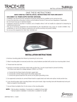
Open fixture Insert and rotate
screwdriver
Fig. 1
Knock out center
hole along the
groove
Fig. 2
Backplate
Black 120-277V AC
White Common/Neutral
Green Ground
Backplate
Front
Cover
IMPORTANT SAFEGUARDS
READ AND FOLLOW ALL SAFETY INSTRUCTIONS.
When using electrical equipment, basic safety precautions should always be followed including the following:
• DISCONNECT AC POWER SUPPLY BEFORE SERVICING.
• Installation and servicing of this equipment should be performed by qualified service personnel only.
• Ensure that the electrical wiring conforms to the National Electrical Code NEC® and local regulations if applicable.
• Do not mount near gas or electric heaters.
• Equipment should be mounted in locations and at heights where it will not be readily subjected to tampering by
unauthorized personnel.
• The use of accessory equipment not recommended by the manufacturer may cause an unsafe condition.
• Any modification or use of non-original components will void the warranty and product liability.
• Do not use this equipment for other than intended use.
SAVE THESE INSTRUCTIONS!
Wall Mount
1. Use a flat blade screwdriver to remove the front cover
from the backplate. (Fig. 1)
2. Remove appropriate knockouts on the backplate
for mounting. (Fig. 2)
Fig. 3
Conduit Plug

800.533.3948 • www.barronltg.com
2
20070101 REV 7 - 03/19
Conduit Mounting
1. Use a flat blade screw driver to remove the front cover from the backplate. (Fig. 1)
2. Remove the conduit plug from the top of the fixture. (Fig. 2)
3. Install the fixture to the surface and secure conduit to fixture.
4. Electrical connections should be made inside the junction box as follows.
White - Common/Neutral
Black - 120V-277V
Green - Ground
Cap any unused leads to prevent shorting.
This fixture auto adjusts for voltages between 120VAC - 277VAC (Fig. 3)
5. Replace the front cover to the backplate.
Luminaire ON / OFF Controls
There are 2 default ON/OFF controls settings:
1. Standard setting ON/OFF controlled by photo-sensor.
a. If ambient illumination is less than 10Lx it will turn on automatically.
b. If illumination is greater than 30Lx, the luminaire will turn off.
2. Unit wall switch control conversion. (See below)
Once unit has been converted to wall switch controls, this will bypass the photo-sensor.
Convert Unit Control from Photo-sensor to Wall Switch
1. Slide the switch away from the driver to convert photo-sensor to wall switch. (Fig. 4)
2. Connect external wall switch to hot wire. (Fig. 5)
Note: Switch not available with motion sensor models. Switch control only available with SLW-NS models.
Motion sensor models cannot have photocontrol nor motion sensor disabled.
IMPORTANT: To weather-proof your fixture, be sure to seal all holes in housing (mounting, conduit, plugs, etc.)
with silicone sealant. Apply sealant across top edge to prevent water from reaching the back of the housing.
INSTALLATION INSTRUCTIONS
SLW
Photo-sensor Wall Switch Position
Fig. 4 Fig. 5

3. Feed the power supply wires through the center hole and
secure the backplate to the junction box with screws provided.
4. Electrical connections should be made inside the junction box
as follows.
White - Common/Neutral
Black - 120V-277V
Green - Ground
Cap any unused leads to prevent shorting. This fixture
auto adjusts for voltages between 120VAC - 277VAC (Fig. 3)
INSTALLATION INSTRUCTIONS
800.533.3948 • www.barronltg.com
1
SLW w/EM
20070105 REV 6 - 05/18
IMPORTANT SAFEGUARDS
READ AND FOLLOW ALL SAFETY INSTRUCTIONS.
When using electrical equipment, basic safety precautions should always be followed including the following:
• DISCONNECT AC POWER SUPPLY BEFORE SERVICING.
• Installation and servicing of this equipment should be performed by qualified service personnel only.
• Ensure that the electrical wiring conforms to the National Electrical Code NEC® and local regulations if applicable.
• Do not mount near gas or electrical heaters.
• Equipment should be mounted in locations and at heights where it will not be readily subjected to tampering by
unauthorized personnel.
• The use of accessory equipment not recommended by the manufacturer may cause an unsafe condition.
• Any modification or use of non-original components will void the warranty and product liability.
• Do not use this equipment for other than intended use.
SAVE THESE INSTRUCTIONS!
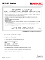
Backplate
Front
Cover
LED driver
Battery
connector
Black 120-277VAC
White Common/Neutral
Green Ground
Open fixture Insert and rotate
screwdriver
Fig. 1
Knock out center
hole along the
groove
Fig. 2
Backplate
Conduit Plug
Wall Mount
1. Use a flat blade screwdriver to remove the front cover
from the backplate. (Fig. 1)
2. Remove appropriate knockouts on the backplate for
mounting. (Fig. 2)
Fig. 3
Fig. 3a
AC input
Neutral (White)
Hot wire (120-277V)
Black Jumper
cable
Switchable Live
Ground (Green) Back plate grounding
Output to driver
Terminal block
Wiring Diagram

800.533.3948 • www.barronltg.com
2
5. Connect the male battery connector to the female connector on the LED driver. (Fig. 3a)
6. Connect the heater pad and ensure proper wiring, refer to the Heater Pad Connections.
7. Replace the front cover to the backplate and test the unit, refer to the Self-test/Self-diagnostics section.
Note: If AC power is lost, the unit will come on for 90 minutes in emergency mode, refer to the Self-test/
Self-diagnostics section. The PIR/motion detector operation cannot be overridden.
Conduit Mounting
1. Use a flat blade screw driver to remove the front cover from the backplate. (Fig. 1)
2. Remove the conduit plug from the top of the fixture. (Fig. 2)
3. Install the fixture to the surface and secure conduit to fixture.
4. Electrical connections should be made inside the junction box as follows.
White - Common/Neutral
Black - 120V-277V
Green - Ground
Cap any unused leads to prevent shorting. This fixture auto adjusts for voltages between 120VAC - 277VAC (Fig. 3)
5. Replace the front cover to the backplate and test the unit, refer to the Self-test/Self-diagnostics section.
Note: If AC power is lost, the unit will come on for 90 minutes in emergency mode, refer to the Self-test/ Self-
diagnostics section. The PIR/motion detector operation cannot be overridden.
Luminaire ON/OFF Controls
There are 2 default ON/OFF controls settings:
1. Standard setting ON/OFF controlled by photo-sensor.
a. If ambient illumination is less than 10Lx it will turn on automatically.
b. If illumination is greater than 30Lx. the luminaire will turn off.
2. Luminaire controlled by photo-sensor and passive Infrared (PIR) motion detection mode.
a. If ambient illumination is less than 10Lx and the PIR sensor detects human movement, luminaires will turn on
automatically.
b. If ambient illumination is greater than 30Lx the luminaires stay off.
Note: If AC power is lost, the unit will come on for 90 minutes in emergency mode.
PIR/motion detector operation cannot be overridden.
Heater Pad Connections
If the unit has a heater pad option for cold weather, refer to the wiring diagrams.
1. For 120VAC factory wiring, no change or rewiring is required. (Fig. 4)
2. For 277VAC heater pad, connect red to blue wire and cap black wire. Refer to 277V wiring diagram. (Fig. 5)
INSTALLATION INSTRUCTIONS
SLW w/EM
20070105 REV 6 - 05/18
LN
KSD301
RED
RED
O
0 C
KSD301
O
0 C
BLACK
BLUE
YELLOW
277VAC supply from LED driver
L
N
Thermal P rotecto r
277VAC
(Wiring requirements)
L N
RED
RED
Fig. 5
L
N
KSD301
O
0 C
KSD301
O
0 C
BLACK
BLUE
YELLOW
120VAC supply from LED driver
L
N
Thermal P rotecto r
RED
RED
120VAC
(Factory wiring)
L N
RED
RED
Fig. 4

Self-test/Self-diagnostics Option
1. When AC power is supplied to fixture, the unit will automatically initiate a Self-test/Self-diagnostic
as follows:
• It will test for battery disconnection, charger board failure, lamps failure and transformer failure at every 5 seconds.
• Run a 3 minute self-test once a month.
• Run a 90 minute self-test every 12 months after installation.
2. Dual color LED lamp indicator shows the following status:
• Green color: ON/ Ready
Blinking: Testing
• Red color (Service Alert)
• Service Alert LED Code (Red color LED lamp indicator)
CAUTION:
After solving the fault of emergency equipment, please press test button for 2 seconds without releasing to reset.
LED indicator will show green.
3. For manual test, press test button as follows:
IMPORTANT: To weather-proof your fixture, be sure to seal all holes in housing (mounting, conduit, plugs, etc.)
with silicone sealant. Apply sealant across top edge to prevent water from reaching the back of the housing.
800.533.3948 • www.barronltg.com
3
INSTALLATION INSTRUCTIONS
SLW w/EM
One blink ON/pause (4 seconds) Battery is not connected
Two blinks ON/pause (4 seconds) Battery is shorted or battery voltage drops below acceptable level
Three blinks ON/pause (4 seconds) Charger board circuit fault
Four blinks ON/pause (4 seconds) Transfer fault
Five blinks ON/pause (4 seconds) Emergency lamp fault
Press test button once (within 2 seconds)
30 second test
Press test button twice (within 2 seconds) 3 minutes test
Press test button 3 times (within 2 seconds) 30 minutes test
Press test button 4 times (within 2 seconds) 90 minutes test
20070105 REV 6 - 05/18
/