Page is loading ...

R
S P E C I F I C AT I O N S U B M I T TA L Page
Job Name:
Job Number:
Model Numbers:
QS System QSE-CI-NWK-E Control Interface
369373b 1 06.21.12
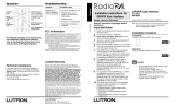
QSE-CI-NWK-E Control Interface
The QSE-CI-NWK-E is a versatile integration access
point for Lutron’s QS-based systems. Through either
RS232 or TCP/IP over Ethernet, third-party devices
can control and/or monitor a QS system.
Key Features
•Easilyintegratewithtouchscreens,PCs,A/Vsystems,
or other digital systems and devices.
•ControlandmonitorGRAFIKEye
® QS, Sivoia® QS,
Energi Savr Node
TM,andotherproductsonthewired
QS link.
•Monitorlightingscenes,levels,andshadepositions
•Uptoten(10)QSE-CI-NWK-Econtrolinterfacesare
allowedperQSlink.
•TheQSE-CI-NWK-EisQuantum
® compatible. Refer to
the Quantum
® System Specification Sheet for
compatibility details.
Compatible Components
ThefollowingdevicesarecompatiblewiththeQSlink.
Formoreinformationoneach,referto
www.lutron.com/qs.
•GRAFIKEye
® QS control units.
•seeTouch
®QSwallstations.
•Sivoia
® QS shades.
•QSInterfaces(contactclosure,Ethernet/RS232).
•Quantum
® system.
•EnergiSavrNode
TM units.
•QSSensorModule.
•QSKeyswitch.
Requirements
•QSLinkPowerSupply,suchasa:
-GRAFIKEye
® QS.
-QSLinkpowersupply,suchastheQSPS-P1-1-50.
- Energi Savr Node
TM QS.
•QSCommunicationLink(IECPELV/NEC
®Class2)
(seeQSLinkWireSizestable).
Protocol
•ProtocoldocumentP/N040-249includedona
CD accompanying the packaged QSE-CI-NWK-E.
•Alsoavailablefordownloadatwww.lutron.com/qs.
1

R
S P E C I F I C AT I O N S U B M I T TA L Page
Job Name:
Job Number:
Model Numbers:
QS System QSE-CI-NWK-E Control Interface
369373b 2 06.21.12
Specifications
Power
•IECPELV/NEC
® Class 2
•Operatingvoltage:12–24V
65mA
QS Link Limits
•TheQSwiredcommunicationslinkislimitedto
100devicesand100zones.EachQSE-CI-NWK-E
controlinterfacecountsas2devicesand2zones.
•EachQSE-CI-NWK-Econtrolinterfaceconsumes
2powerdrawunits(PDU)ontheQSlink.Refer
totheQSLinkPowerDrawUnitsSpecication
Submittal(LutronPN369405,atwww.lutron.com)
for more information.
•ThemaximumwiringlengthfortheQSlinkis2000ft
(610m).
Environment
•32to104°F(0to40°C).
•Relativehumiditylessthan90%non-condensing.
Integration Features
•Monitoring:Currentscene,zonelevel,button
presses, shade group levels.
•Control:Sceneselection,scenelockout,zone
lockout,sequencing,zoneraise/lower,masterraise/
lower,setshadegrouplevel,simulatebuttonpress/
release.
Forthefulllistoffeaturesandcommands,please
refer to the protocol document on the
accompanying CD, also available at
www.lutron.com.
RS232 Connection
•Standard9-pinfemaleserialconnectoroninterface.
•50ft(15m)maximumserialcablelength.
•Dipswitchesaresetatfactory,allOff.
•DipswitchesareusedtosetRS232baudrate:
DIP Switch Settings for RS232 Baud Rate
115200(default)
38400
19200
9600
Ethernet Connection
•StandardCAT5(orbetter)cable,328ft(100m)
maximum,connectstheQSE-CI-NWK-Einterfacetoa
PC or other Ethernet source.
•SupportsMDI/MDIXauto-crossover(nocrossover
cableneeded).
•Auto-negotiationof10or100Mbpsspeedandfull-or
half-duplexoperation.
•DefaultIPaddressis192.168.250.1.Canbechanged
using the Lutron DeviceIP tool located on the
accompanying CD.
Note: Either the RS232 or the Ethernet can be used,
but not both.
115200
38400
19200
9600
1 2 3 4 5 6 7 8
1 2 3 4 5 6 7 8
1 2 3 4 5 6 7 8
1 2 3 4 5 6 7 8
115200
38400
19200
9600
1 2 3 4 5 6 7 8
1 2 3 4 5 6 7 8
1 2 3 4 5 6 7 8
1 2 3 4 5 6 7 8
115200
38400
19200
9600
1 2 3 4 5 6 7 8
1 2 3 4 5 6 7 8
1 2 3 4 5 6 7 8
1 2 3 4 5 6 7 8
115200
38400
19200
9600
1 2 3 4 5 6 7 8
1 2 3 4 5 6 7 8
1 2 3 4 5 6 7 8
1 2 3 4 5 6 7 8
2

R
S P E C I F I C AT I O N S U B M I T TA L Page
Job Name:
Job Number:
Model Numbers:
QS System QSE-CI-NWK-E Control Interface
369373b 3 06.21.12
2.47
(62.7)
3.75
(95.3)
4.26
(108.2)
5.26
(133.6)
1.06
(26.9)
Mounting holes
Terminal
blocks
on this side
LEDs and addressing
switchesonthisside
Dimensions
Dimensionsareininches(mm)
0.34
(8.6)dia.
0.18
(4.6)dia.
0.18
(4.6)dia.
0.25
(6.4)
#6or#8(M3orM4)
screwrecommended
Mounting Hole Detail
Mounting Options
Mounting Methods
Mountwhereterminalblocks,switches,andLEDsare
accessible. Strip 4in(10mm)ofinsulationfrom
wires.Eachdatalinkterminalwillacceptuptotwo
18AWG(1.0mm
2
)wires.Connectwiringasshown
ontheWiringpage.Choosefromthefollowing
mountingmethods:
1: Direct Wall Mounting
Mountthecontrolinterfacedirectlyonawall,as
showninMountingMethodsatright,usingscrews
(notincluded).Whenmounting,providesufcient
space for connecting cables.
2: Rack Mounting
PlacetheunitcanintheLUT-19AV-1UAVrackusing
screws(notincluded).TheLUT-19AV-1Uwillholdup
to four units.
3: Enclosed Wall Mounting
Ifconduitisdesiredforwiring,usethe
LUT-5x10-ENCtomountoneunit.
LUT-19AV-1U
2
LUT-5x10-ENC
5.26
4.263.75
2.50
1.06
Control Interface
Wall
1
3
3

R
S P E C I F I C AT I O N S U B M I T TA L Page
Job Name:
Job Number:
Model Numbers:
QS System QSE-CI-NWK-E Control Interface
369373b 4 06.21.12
Terminal Locations
LED and DIP Switch Locations
Ethernet Link
(toPCorAV
Equipment
Female9-pin
RS232Link(to
PCorAV
Equipment)
QS Link to
otherwired
QS system
Devices
Toexternal
powersupply
DIPSwitches
LED1:Power
LED2:EthernetActivity
LED3:Unused
LED4:RS232LinkTx
LED5:RS232LinkRx
LED6:QSLinkTx
LED7:QSLinkRx
1 2 3 4 5 6 7
4

R
S P E C I F I C AT I O N S U B M I T TA L Page
Job Name:
Job Number:
Model Numbers:
QS System QSE-CI-NWK-E Control Interface
369373b 5 06.21.12
Wiring
RS232 Link
•Standard9-pinserialconnectorplugsintoRS232
equipment,andtoQSE-CI-NWK-E.
•Mustbe50ft(15m)orless.
RS232 Signals
Signals Pin on 9-Pin Cable
Com 5
TxD 3
RxD 2
1 2 3 4
1 2
A B C
1 2 3 4 5 6 L N
4 3 2 1
To additional QS devices
RS232 Cable
50ft(15m)
max.
EthernetLink:CAT5Cable:328ft(100m)max.
COM
TxD
RxD
RS232 Link
ToPCorAV
Equipment
RearViewofGRAFIKEye®QSControlUnit
Toexternalpowersupply
QSLink:
1:Common
2:Power
3:MUX
4:MUX
Seenextpage.
Do not connect Pin 2 if using
externalpowersupply.
QS Link
Ethernet Link Wiring
•StandardCAT5cableconnectsQSE-CI-NWK-E
Interface to PC, router, or other Ethernet source.
•Nocrossovercableneeded.
•Mustbe328ft(100m)orless.
•Ethernetnetworkandcableprovidedbyothers.
5

R
S P E C I F I C AT I O N S U B M I T TA L Page
Job Name:
Job Number:
Model Numbers:
QS System QSE-CI-NWK-E Control Interface
369373b 6 06.21.12
Wiring (continued): QS Link Wiring Methods (choose one)
Powered by GRAFIK Eye® QS Control Unit
Powered by a QS Link Power Supply
1 2 3 4
1 2
A B C
1 2 3 4 5 6 L N
4 3 2 1
Toadditionalwallstations/
control interfaces
Toadditionalwallstations/
control interfaces
RearViewofGRAFIKEye
® QS
ControlUnit
RearViewof
GRAFIKEye
® QS
ControlUnit
QS
Link
QS
Link
QS Link
1:Common
2:Power
3:MUX
4:MUX
DataLink:
4:MUX
3:MUX
See QS Link
WireSizestable
IECPELV/NEC®Class2Powerwiring:
2:Power
1:Common
SeeQSLinkWireSizestable
•SystemcommunicationusesIECPELV/NEC® Class 2
wiring.
•Followalllocalandnationalelectricalcodeswhen
installingIECPELV/NEC
®Class2wiringwithline
voltage/mainswiring.
•Eachterminalacceptsuptotwo18AWG(1.0mm²)
wires.
•Totallengthofcontrollinkmustnotexceed2000ft
(610m).
•TypicalWireSizes:SeeQSLinkWireSizestable.
•Connecttheterminal1,3,and4connectionstoall
controlunits,wallstations,andcontrolinterfacesinthe
QSsystem.Forterminal2connectivity,seebelow.
4 3 2 1
Lutron Cable
SeeQSLinkWireSizestable
QSPS-P1-1-50
(providesupto8
powerdrawunits)
Topowersource
(1)18AWG
(1.0mm
2
)
Common
(1)twistedpair
22AWG
(0.5mm
2
)
QS Link Wire Sizes (check compatibility in your area)
QS Link Wiring Length Wire Gauge Lutron Cable Part Number
<500ft(153m)
Power(terminals1and2)
1pair18AWG(1.0mm
2
)
GRX-CBL-346S(non-plenum)
GRX-PCBL-346S(plenum)
Data(terminals3and4)
1twisted,shieldedpair22AWG(0.5mm
2
)
500–2000ft
(153–610m)
Power(terminals1and2)
1pair12AWG(4.0mm
2
)
GRX-CBL-46L
(non-plenum)
GRX-PCBL-46L(plenum)
Data(terminals3and4)
1twisted,shieldedpair22AWG(0.5mm
2
)
Do not use
external
powersupply
if connecting
Pin 2
Donotuseexternalpower
supply if connecting Pin 2
6
/