Page is loading ...

Four Mounting Holes
Diameter - 0.25 in. (6mm) Four Screws
Secure Cover
6.10 in.
(155 mm)
3.30 in.
(84 mm)
12.50 in.
(318 mm) Wall
11.75 in.
(298 mm)
4.0 in.
(102 mm)
COOPERSBURG, PA 18036 U.S.A.
G 2 CB
144-317 Rev. 1.9
0-10V INTERFACE CONTROL
Control Input:
100-120V, 220-240V 50/60Hz
Switched Output: 100-277
GRX-TVI
Incandescent 16A
Fluorescent 5A
Magnetic Low-voltage 16A
Electronic Low-voltage 16A
Neon/Cold Cathode 16A
Motor 1/4 HP@120V
1/2 HP@277V
®
Control
GRX-TVI Input Rating
IH20.02A
IDH20.1A
Load Type Switched
Ratings ®
10A
5AX
10A
10A
10A
Control
GRX-TVI Input Rating
IH20.02A
IDH20.1A
Load Type Switched
Ratings ✔ACN
003 715 277
0-10V Output Rating
Max. 0.3A PELV
0-10V Output Rating
Max. 0.3A Class 2
Switched µ
Installation and Operation Instructions
Read Before Installing
Occupant Copy
GRX-TVI Control Interface
Phase Control to 0-10V
Description
The GRX-TVI provides 0-10V control and ballast switching capabili-
ties in one enclosure. The GRX-TVI gives GRAFIK Eye 3000 Series
Control Units the ability to control any 0-10V ballasts powered by
100V-277V (ballast must provide 0-10V sourcing of current)
and provides switching relays that can handle the in-rush current for a
circuit of ballasts. The GRX-TVI gives a GRAFIK Eye 3000 Series
Control Unit the ability to both dim and switch electronic ballasts,
such as Lutron's Eco-10™(TVE models). The GRX-TVI can also be
used to switch any of the load types listed below.
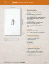
Note: When using a Control Unit, a GRX-TVI is required for each 0-10V
fluorescent zone. (A 3-zone Control Unit with two fluorescent zones
and one incandescent zone is shown as an example.)
Mounting
Find a suitable location for mounting.
nDecide on the proper location for the GRX-TVI (NEMA Type 1
enclosure, indoor use only). See System Wiring Layout below.
nThe environment where the GRX-TVI is placed must have an
ambient temperature range of 32—104 °F (0—40 °C).
nMount the enclosure vertically on a wall (screws not provided). See
Mounting Diagram below.
nMounting method must be able to support weight and forces
applied during installation.
nIinternal relays will click while in operation — mount where
audible noise is acceptable.
System Wiring Layout
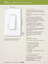
Mounting Diagram
Product Specifications
Four Mounting Holes
Diameter: 0.25 in. (6 mm) Four Screws Secure Cover
12.5 in.
(318 mm)
3.30 in.
(84 mm)
6.10 in.
(155 mm)
LUTRON LUTRON
LUTRON
0-10V Control Fluorescent Zone/Load 1
0-10V Control Fluorescent Zone/Load 1
0-10V Ballast
Power from
Distribution
Panel
GRX-
TVI GRX-
TVI
Ballast
Switched Fluorescent Zone/Load 2
Incandescent Zone/Load 3
Control Unit Class 2/PELV Accessory Controls
0-10V Ballast
COOPERSBURG, PA 18036 U.S.A.
G 2 CB
144-317 Rev. 1.9
0-10V INTERFACE CONTROL
Control Input:
100-120V, 220-240V 50/60Hz
Switched Output: 100-277
GRX-TVI
Incandescent 16A
Fluorescent 5A
Magnetic Low-voltage 16A
Electronic Low-voltage 16A
Neon/Cold Cathode 16A
Motor 1/4 HP@120V
1/2 HP@277V
®
Control
GRX-TVI Input Rating
IH20.02A
IDH20.1A
Load Type Switched
Ratings ®
10A
5AX
10A
10A
10A
Control
GRX-TVI Input Rating
IH20.02A
IDH20.1A
Load Type Switched
Ratings ✔ACN
003 715 277
0-10V Output Rating
Max. 0.3A PELV
0-10V Output Rating
Max. 0.3A Class 2
Switched µ
4.0 in.
(102 mm)
11.75 in.
(298 mm) WALL
100-127V/
200-277V
230V (CE)
FEATURES.....................Provides a Class 2/PELV isolated 0-10V output signal that
conforms to EN60929 and IEC60929
Accepts a constant-gate drive fluorescent signal (100-127V,
220-240V, 50/60Hz)
INPUT POWER RATING................100-127/220-240V, 50/60Hz
H2/L2 TERMINAL.........................20mA
INPUT RATING
DH2/DL2 TERMINAL.....................100mA
INPUT RATING
0-10V OUTPUT RATING...............10µA-300mA - Sinks current only (maximum 150
ballasts)
Source/Load Type
Fluorescent:
Lutron Eco-10T
(TVE Series)
Electronic Capacitive
Non-Dim
Other Manufacturer’s 0-10V
Ballasts (0-10V source only)
Incandescent
Low-Voltage
Metal Halide
Neon/Cold Cathode
16A
16A
16A
16A
16A
16A
16A
—
10A
10A
10A
10A
10A
10A
Motors 1/4HP @ 100-120V
1/2HP @ 200-277V
1/2HP @ 230V CE
TERMINALS Two #12-20AWG (0.5-2.5 mm2) conductors per terminal.
MOUNTING NEMA Type 1 enclosure, indoor use only.
ENVIRONMENTAL 32—104 ˚F (0—40 ˚C).
WEIGHT 4.25 lb. (2kg)
100-127V and 220-240V/CE
English Italiano

2
220-240V/CE Control Interface
Important Installation Information
Install in accordance with all national and local electrical codes.
Check for short circuited loads during new installations before wiring the GRX-TVI.
Caution: Multiple feeds may enter this enclosure. Locate and lock each feed circuit breaker/MCB in the OFF position
before wiring the Interface.
Proper short circuit and overload protection must be provided at the distribution panel. You can use up to a 20A (16A for CE)
maximum circuit breaker/MCB or equivalent (tripping curve C according to IEC 898/EN60898 is recommended) with adequate
short circuit breaking capacity for your installation.
Terminal blocks are rated for two #12-22 AWG (0.5-2.5 mm2) wires per terminal.
Strip 3/8 in. (10 mm) of insulation from wires.
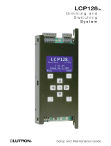
Wiring Diagram A shows a GRX-TVI wired from one distribution panel. If the
power requirement of the complete system is less than an MCB/circuit
breaker rating, one feed can be jumpered inside the enclosure (as shown).
Wiring Diagram B shows a GRX-TVI wired from two separate distribution panels that may be different phases or voltages.
Use the internal terminal block label to see where to land wires.
—The label shows two separate Hot/Live terminals (L1/H1& L2/H2).
L1/H1is the Hot/Live feed to power the lighting load.
L2/H2is the Hot/Live feed that powers internal circuitry of the GRX-
TVI.
L2/H2has a 100-127V connection and a 220-240V connection - use
only the one corresponding to line voltage for your application.
Note 1: Not all terminal blocks receive a connection.
Note 2: The power feed to the Control Unit and L2/H2of the GRX-
TVI must be the same phase!
Class 2/PELV, 0-10V wiring from a ballast to the GRX-TVI-
CE must be separated from the power wiring. Enter the
Class 2/PELV wires through the knockout adjacent to the 0-10V terminal blocks. The Nomex®barrier ensures
separation and is flexible to allow access to the terminals. The barrier must be in place when installation is
complete.
GRX-TVI Internal Terminal Block Label Definitions
Use only one input according to Input Voltage:
L2/H2240V Power input for GRX-TVI control (line/mains voltage must be 220-240V)
L2/H2127V Power input for GRX-TVI control (line/mains voltage must be 100-127V)
N2 Neutral for GRX-TVI control
DL2/DH GRAFIK Eye 3000 Series Control Unit Lighting Zone connection (Phase Control Input to GRX-TVI)
L1/H1Power input for lighting load
N1Neutral for lighting load (2 terminals provided and internally tied together — one for input neutral and one
for load neutral)
SL1/SH1Switched output to power lighting load
+ - 0-10V control signal wires (ballast must provide a 0-10V source only)
10mm
(3/8in.)
L2/H2 100-127V
N2
DL2/DH2
L1/H1 100-277V
N1
N1
SL1/SH1
0-10 Volt
L
2
/H
2
220-240V/CE
Use only if
your
line/mains
voltage is
220-240V.
Use only if your line/mains voltage is
120-127V.
Input from distribution
panel.

100-
127V
220-
240V
N2
DL2/DH2
L1/H1
N
1
N
1
SL1/SH1 + –
Max 0.3A
0-10V
Control Inputs Load Switched
L2/H2 100-
277V
EARTH/GROUND
CONNECTIONS
L2/H2 100-120V
N2
DL2/DH2
L1/H1
N1
N1
SL1/SH1
0-10 Volt
NEUTRAL
L2/H2 220-240V
L2/H2 100-127V
N2
DL2/DH2
L1/H1 100-277V
N1
N1
SL1/SH1
0-10 Volt
L
2
/H
2
220-240V/CE
–
+
SL1/SH1
N1
–
+
SL1/SH1
N1
N
LUTRON
3
Wiring Diagram A: 220-240V/CE GRX-TVI — 1 Distribution Panel
Earth/Ground
GRX-3000
Distribution
Panel
0-10V Ballast
0-10V Ballast
Dimmed Hot/Live
Neutral
Neutral
Neutral
Hot/Live
Switched Hot/Live
Hot/Live
Use 20A (16A CE) maximum
circuit breaker/MCB
To additional ballasts
GRX-TVI
0-10V Control Signal Wires - DO NOT
CONNECT TO LINE VOLTAGE. Lutron is not
liable for damage due to miswiring.
Earth/Ground
Earth/Ground
Wiring Diagram B: 220-240V/CE GRX-TVI — 2 Distribution Panels
EARTH/GROUND
CONNNECTIONS
100-
127V
220-
240V
N2
DL2/DH2
L1/H1
N
1
N
1
SL1/SH1 + –
Max 0.3A
0-10V
Control Inputs Load Switched
L2/H2 100-
277V
EARTH/GROUND
CONNECTIONS
L2/H2 100-120V
N2
DL2/DH2
L1/H1
N1
N1
SL1/SH1
0-10 Volt
NEUTRAL
L2/H2 220-240V
L2/H2 100-127V
N2
DL2/DH2
L1/H1 100-277V
N1
N1
SL1/SH1
0-10 Volt
L
2
/H
2
220-240V/CE
–
+
SL1/SH1
N1
–
+
SL1/SH1
N1
N
LUTRON
N
Earth/Ground
Distribution
Panel
0-10V Ballast
0-10V Ballast
Dimmed Hot/Live
Neutral
Neutral
Neutral
Hot/Live
Switched Hot/Live
Hot/Live
Use 20A (16A CE) maximum
circuit breaker/MCB
To additional ballasts
Note: Ballast must provide a 0-10V
source only!
0-10V Control Signal Wires - DO NOT
CONNECT TO LINE VOLTAGE. Lutron is not
liable for damage due to miswiring.
Earth/Ground
Earth/Ground
EARTH/GROUND
CONNNECTIONS
Earth/Ground
Distribution
Panel Neutral
Hot/Live
GRX-3000
GRX-TVI
Line/Mains Voltage:
220-240V
Line/Mains Voltage:
220-240V
220-240V
220-240V
L2/H2is the Hot/Live feed that powers
the internal circuitry of the GRX-TVI.
Use L2/H2220-240V/CE only if your
line/mains voltage is 220-240V.
L2/H2is the Hot/Live feed that powers
the internal circuitry of the GRX-TVI.
Use L2/H2220-240V/CE only if your
line/mains voltage is 220-240V.

4
100-127V Control Interface
Important Installation Information
Install in accordance with all national and local electrical codes.
Check for short circuited loads during new installations before wiring the GRX-TVI.
Caution: Multiple feeds may enter this enclosure. Locate and lock each feed circuit breaker/MCB in the OFF position
before wiring the Interface.
Proper short circuit and overload protection must be provided at the distribution panel. You can use up to a 20A (16A for CE)
maximum circuit breaker/MCB or equivalent (tripping curve C according to IEC 898/EN60898 is recommended) with adequate
short circuit breaking capacity for your installation.
Terminal blocks are rated for two #12-22 AWG (0.5-2.5 mm2) wires per terminal.
Strip 3/8 in. (10 mm) of insulation from wires.
Wiring Diagram C shows a GRX-TVI wired from one distribution panel. If the
power requirement of the complete system is less than an MCB/circuit
breaker rating, one feed can be jumpered inside the enclosure (as shown).
Wiring Diagram D shows a GRX-TVI wired from two separate distribution panels that may be different phases or voltages.
Use the internal terminal block label to see where to land wires.
—The label shows two separate Hot/Live terminals (L1/H1& L2/H2).
L1/H1is the Hot/Live feed to power the lighting load.
L2/H2is the Hot/Live feed that powers internal circuitry of the GRX-
TVI.
L2/H2has a 100-127V connection and a 220-240V connection - use
only the one corresponding to line voltage for your application.
Note 1: Not all terminal blocks receive a connection.
Note 2: The power feed to the Control Unit and L2/H2of the GRX-
TVI must be the same phase!
Class 2/PELV, 0-10V wiring from a ballast to the GRX-TVI-
CE must be separated from the power wiring. Enter the
Class 2/PELV wires through the knockout adjacent to the 0-10V terminal blocks. The Nomex®barrier ensures
separation and is flexible to allow access to the terminals. The barrier must be in place when installation is
complete.
GRX-TVI Internal Terminal Block Label Definitions
Use only one input according to Input Voltage:
L2/H2240V Power input for GRX-TVI control (line/mains voltage must be 220-240V)
L2/H2127V Power input for GRX-TVI control (line/mains voltage must be 100-127V)
N2 Neutral for GRX-TVI control
DL2/DH GRAFIK Eye 3000 Series Control Unit Lighting Zone connection (Phase Control Input to GRX-TVI)
L1/H1Power input for lighting load
N1Neutral for lighting load (2 terminals provided and internally tied together — one for input neutral and one
for load neutral)
SL1/SH1Switched output to power lighting load
+ - 0-10V control signal wires (ballast must provide a 0-10V source only)
10mm
(3/8in.)
L2/H2 100-127V
N2
DL2/DH2
L1/H1 100-277V
N1
N1
SL1/SH1
0-10 Volt
L
2
/H
2
220-240V/CE
Use only if
your
line/mains
voltage is
220-240V.
Use only if your line/mains voltage is
120-127V.
Input from distribution
panel.

5
Wiring Diagram C: 100-127V GRX-TVI — 1 Distribution Panel
100-
127V
220-
240V
N2
DL2/DH2
L1/H1
N
1
N
1
SL1/SH1 + –
Max 0.3A
0-10V
Control Inputs Load Switched
L2/H2 100-
277V
EARTH/GROUND
CONNECTIONS
L2/H2 100-120V
N2
DL2/DH2
L1/H1
N1
N1
SL1/SH1
0-10 Volt
NEUTRAL
L2/H2 220-240V
L2/H2 100-127V
N2
DL2/DH2
L1/H1 100-277V
N1
N1
SL1/SH1
0-10 Volt
L
2
/H
2
220-240V/CE
–
+
SL1/SH1
N1
–
+
SL1/SH1
N1
N
LUTRON
Earth/Ground
GRX-3000
Distribution
Panel
0-10V Ballast
0-10V Ballast
Dimmed Hot/Live
Neutral
Neutral
Neutral
Hot/Live
Switched Hot/Live
Hot/Live
Use 20A (16A CE) maximum
circuit breaker/MCB
To additional ballasts
Note: Ballast must provide a 0-10V
source only!
GRX-TVI
0-10V Control Signal Wires - DO NOT
CONNECT TO LINE VOLTAGE. Lutron is not
liable for damage due to miswiring.
Earth/Ground
Earth/Ground
Wiring Diagram D: 100-127V GRX-TVI — 2 Distribution Panels
EARTH/GROUND
CONNNECTIONS
100-
127V
220-
240V
N2
DL2/DH2
L1/H1
N
1
N
1
SL1/SH1 + –
Max 0.3A
0-10V
Control Inputs Load Switched
L2/H2 100-
277V
EARTH/GROUND
CONNECTIONS
L2/H2 100-120V
N2
DL2/DH2
L1/H1
N1
N1
SL1/SH1
0-10 Volt
NEUTRAL
L2/H2 220-240V
L2/H2 100-127V
N2
DL2/DH2
L1/H1 100-277V
N1
N1
SL1/SH1
0-10 Volt
L
2
/H
2
220-240V/CE
–
+
SL1/SH1
N1
–
+
SL1/SH1
N1
N
LUTRON
N
Earth/Ground
Distribution
Panel
0-10V Ballast
0-10V Ballast
Dimmed Hot/Live
Neutral
Neutral
Neutral
Hot/Live
Switched Hot/Live
Hot/Live
Use 20A (16A CE) maximum
circuit breaker/MCB
To additional ballasts
0-10V Control Signal Wires - DO NOT
CONNECT TO LINE VOLTAGE. Lutron is not
liable for damage due to miswiring.
Earth/Ground
Earth/Ground
EARTH/GROUND
CONNNECTIONS
Earth/Ground
Distribution
Panel Neutral
Hot/Live
GRX-3000
GRX-TVI
120-127V
120-127V
Line/Mains Voltage:
120-127V
Line/Mains Voltage:
120-127V
L2/H2is the Hot/Live feed that powers
the internal circuitry of the GRX-TVI.
Use L2/H2100-127V only if your
line/mains voltage is 120-127V.
L2/H2is the Hot/Live feed that powers
the internal circuitry of the GRX-TVI.
Use L2/H2100-127V only if your
line/mains voltage is 120-127V.
Chinese

Operation
After wiring is complete, supply power to the GRX-TVI to check for proper operation.
■With the cover removed, an LED will provide visual feedback about the operation of the system.
■When power is first applied, the LED will turn on for 8 seconds to indicate start-up mode and then start to flash in one of two ways to
indicate the status of the system:
1. Standard Operation
■The LED will flash at a rate of twice per second to signify proper communication between the Control Unit and the Interface.
2. Incorrect Operation - No Active Input
■The LED will repeatedly turn on for 1 second then off for 1 second to indicate that there is not an active phase control input to the GRX-
TVI. Make sure that the phase control dimmer is ON and connected to the GRX-TVI at the terminal block marked DL2/DH2. Check that
the corresponding zone for the DL2/DH2terminal is ON and the light level is not set at the minimum output.
■When the LED indicates proper input of a phase control signal, then the output can be checked by looking at the load and checking operation
from the Control Unit.
■For non-dimming ballasts, select non-dim load type on the GRAFIK Eye Control Unit and do not connect ballasts to 0-10V terminals.
Make sure that the Control Unit is set for Fluorescent Load Type. (Refer to GRAFIK Eye 3000 Series Installer's Guide.) If the load
type is not set correctly, proper dimming will not occur.
Lutron Electronics Co., Inc.
Made and printed in U.S.A. 8/03
P/N 032-119 Rev. B
FRANCE
Lutron LTC
International +33-1-44-70-72-00
Int’l Fax: +33-1-44-70-00-19
ASIAN HEADQUARTERS
Lutron Asuka Corporation (Japan)
Tel:(03)-5575-8411;
International (03)-5575-8411
Fax: +(03) -5575-8420;
International +81-3-5575-8420
HONG KONG SALES OFFICE
Lutron GL (Hong Kong)
Tel: 2104-7733;
International +852-2104-7733
Fax: 2104-7633;
International +852-2104-7633
SINGAPORE
Lutron GL (Singapore)
Tel: +65-6220-4666
Fax: +65-6220-4333
Internet: www.lutron.com
E-mail: [email protected]
WORLD HEADQUARTERS
Lutron Electronics Co. Inc.,
TOLL FREE: (800) 523-9466
(U.S.A., Canada, Caribbean)
Tel: (610) 282-3800;
International +1- 610-282-3800
Fax: (610) 282-1243;
International +1-610-282-1243
EUROPEAN HEADQUARTERS
Lutron EA Ltd.,
Tel: (207) 702-0657;
International +44-207-702-0657
Fax: (207) 480-6899;
International +44-207-480-6899
GERMANY
Lutron Electronics GmbH
Tel: (309) 710-4590;
International +49-309-710-4590
Fax: (309) 710-4591;
International +49-309-710-4591
LIMITED WARRANTY
Lutron will, at its option, repair or replace any unit that is defective in materials or
manufacture within one year after purchase. For warranty service, return unit to place of
purchase or mail to Lutron at 7200 Suter Rd., Coopersburg, PA 18036-1299, postage pre-
paid.
This warranty is in lieu of all other express warranties, and the implied
warranty of merchantability is limited to one year from purchase. This
warranty does not cover the cost of installation, removal or reinstallation, or
damage resulting from misuse, abuse, or improper or incorrect repair, or
damage from improper wiring or installation. This warranty does not cover
incidental or consequential damages. Lutron’s liability on any claim for
damages arising out of or in connection with the manufacture, sale,
installation, delivery, or use of the unit shall never exceed the purchase price
of the unit.
This warranty gives you specific legal rights, and you may also have other rights which vary
from state to state. Some states do not allow limitations on how long an implied warranty
lasts, so the above limitation may not apply to you. Some states do not allow the exclusion or
limitation of incidental or consequential damages, so the above limitation or exclusion may
not apply to you.
Nomex is a registered trademark of E.I. Du Pont de Nemours and Company.
Lutron and GRAFIK Eye are registered trademarks; Eco-10 is a trademark of Lutron
Electronics Co., Inc.
© 2003 Lutron Electronics Co., Inc.
Solution
Verify that LED pulses twice per second. If not, check wiring from phase control unit to the Interface.
Make sure that the GRAFIK Eye 3000 Series Control Unit is ON.
Check for proper polarity of 0-10V signals at terminal blocks. Does it match what is at every ballast? A
miswire at any ballast will cause all ballasts to go to the low end.
GRAFIK Eye 3000 Series Control Unit is not configured for fluorescent load type.
Check that the SL1/SH1connection goes to the ballasts.
Check that the DL2/DH2connection is actually wired to a phase control input.
Load is not connected to SH (SL) terminal.
Check that the DL2/DH2connection is actually wired to a phase control input.
Check that power is applied to the Interface.
Symptom
0-10V Ballast does not dim or control
unit to the Interface.
Light does not switch on
Light does not switch off
LED is not illuminated
Possible Cause
Miswire
Power is OFF
Miswire
Incorrect Control Setup
Miswire
Miswire
Miswire
Miswire
No Power Input
Troubleshooting
/