Page is loading ...

Español Français Português Deutsch Italiano Nederlands
中文
www.lutron.com1
English
Installation and Operation Instructions
Please Read Before Installing
Occupant Copy
GRX-TVI Control Interface
Phase Control to 0-10 V-
100-277 V~ 50 / 60 Hz
Description
The GRX-TVI provides 0-10 V- control and ballast/driver switching
capabilities in one enclosure. The GRX-TVI gives a 100-277 V~
dimmer the ability to control current sourcing 0-10 V- ballasts
or LED drivers (loads) powered by 100-277 V~. The dimmer can
be forward phase,reverse phase, or center phase (for a sample of
approved dimmers, see the list on spec sheet P/N 369247). The
GRX-TVI provides switching relays that can handle the in-rush
current for a circuit of ballasts/drivers. The GRX-TVI can also be
used to switch any of the load types listed below.
Product Specifi cations
Features.............................. Provides a IEC PELV/NECR Class 2
isolated 0-10 V- output signal that
conforms to EN60929 and IEC60929;
Accepts any phase control signal;
Accepts a constant-gate drive
fl uorescent signal (Control unit should
be confi gured for fl uorescent load type)
Input Power Rating............100-277 V~ 50/60 Hz
H2/L2 Terminal................... 20 mA
Input Rating
DH2/DL2 Terminal..............100 mA
Input Rating
0-10 V- Output Rating..... 10 μA-300 mA - Sinks current only
(maximum 150 ballasts/drivers)
Terminals Two 12 to 20 AWG (2.5 to 0.5 mm
2
) conductors
per terminal.
Mounting NEMA Type 1 enclosure, indoor use only.
Environmental 32 to 104 ˚F (0 to 40 ˚C).
Weight 4.25 lb (2 kg)
COOPERSBURG, PA 18036 U.S.A.
0-10V INTERFACE CONTROL
Control Input: 100-120V,
220-240V 50/60Hz
Switches:
100-277VAC
GRX-TVI
¨
Source/Load Type 230 V~ (CE) 100-277 V~ (Non-CE)
Fluorescent:
Electronic Capacitive
Non-Dim
Other Manufacturer’s 0-10 V-
Ballasts/drivers
(0-10 V- source only)
10 A
10 A
16 A
16 A
LED 10 A 16 A
Incandescent 10 A 16 A
Low-Voltage 10 A 16 A
Metal Halide 10 A 16 A
Neon/Cold Cathode 10 A 16 A
Motors
5 A @ 230 V~ CE 1/2 HP @ 100 - 120V~
1
1
⁄2 HP @ 200 - 277 V~
P/N 032443 Rev. A
Important Installation Information
• Install in accordance with all national and local electrical codes.
• Check for short-circuited loads during new installations before wiring
the GRX-TVI.
WARNING - Shock Hazard. To avoid the risk of electric
shock, locate and remove fuse or lock circuit breaker in the
OFF position before proceeding. Wiring with the power ON
could result in personal injury or death.
Note: Multiple power feeds could be provided. Ensure that all feeds
are off before wiring.
• Proper short circuit and overload protection must be provided at the
distribution panel. You can use up to a 20 A (16 A for CE) maximum
circuit breaker/MCB or equivalent (tripping curve C according to
IEC 898/EN60898 is recommended) with adequate short circuit
breaking capacity for your installation.
• Terminal blocks are rated for two 12 to 20 AWG (2.5 to 0.5 mm
2
)
wires per terminal.
• Strip 3/8 in (10 mm) of insulation from wires.
Note: 277 V~ operation on the control terminal was a design feature
added September 2013. To check whether your TVI has this feature,
please ensure the front label of the TVI shows the acceptable voltage
range as 100 - 277 V~ for the control input. Prior revisions of the unit
had (2) L2/H2 terminals (one for 120 V~ and one for 240 V~). The
current design of the unit accepts a universal voltage (100 - 277 V~),
so either of these terminals can be used for the control feed. They are
internally tied together.
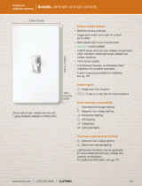
LUTRON LUTRON
0-10 V- Ballast/driver
0-10 V- Ballast/driver
0-10 V- Control Fluorescent Zone/Load 1
0-10 V- Control Fluorescent Zone/Load 1
Switch Fluorescent Zone/Load 2
Incandescent Zone/Load 3
Control Unit / Dimmer
Power from
Distribution
Panel
GRX-
TVI
GRX-
TVI
Ballast/driver
Class 2/PELV Accessory Controls
3/8 in
(10 mm)
Note: When using a Control Unit, a GRX-TVI is required for each 0-10 V-
fl uorescent zone. (A 3-zone Control Unit with two fl uorescent zones and
one incandescent zone is shown as an example.)
System Wiring Layout Overview

www.lutron.com2
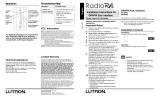
Mounting
Find a suitable location for mounting.
• Decide on the proper location for the GRX-TVI (NEMA Type 1
enclosure, indoor use only).
• The environment where the GRX-TVI is placed must have an
ambient temperature range of 32 to 104 °F (0 to 40 °C).
• Mount the enclosure vertically on a wall (screws not provided).
• Mounting method must be able to support weight and forces
applied during installation.
• Internal relays will click while in operation — mount where
audible noise is acceptable.
Warning - Shock Hazard. To avoid the risk of electric shock,
locate and remove fuse or lock circuit breaker in the OFF
position before proceeding. Wiring with the power ON could
result in personal injury or death.
Diameter - 0.25 in. (6mm)
Four Screws
Secure Cover
6.10 in.
(155 mm)
3.30 in.
(84 mm)
12.50 in.
(318 mm)
Wall
11.75 in.
(298 mm)
4.0 in.
(102 mm)
Mounting Diagram
Four Mounting Holes
Diameter: 0.25 in (6 mm)
Four Screws Secure Cover
11.25 in
(298 mm)
12.50 in
(318 mm)
4.00 in
(102 mm)
6.10 in
(155 mm)
3.30 in
(84 mm)
WALL
N
2
DL
2
/DH
2
L
1
/H
1
100-277 V~
N
1
SL
1
/SH
1
0-10 Volt-
L
2
/H
2
100-277 V~
Wiring
1. Turn power off at fuse box or circuit breaker
Note: Multiple power feeds could be provided. Ensure that all feeds
are off before wiring.
2. Wire control per appropriate wiring diagram (see next page)
using wire connectors provided. Dots on diagrams represent wire
connectors.
• Wiring Diagram A shows a GRX-TVI wired from one distribution
panel. If the power requirement of the complete system is less than
an MCB/circuit breaker rating and L1/H1 and L2/H2 are both coming
from the same phase, one feed can be jumpered inside the enclosure
(as shown on Page 3).
• Wiring Diagram B shows a GRX-TVI wired from two separate
distribution panels that may be different phases or voltages.
• Use the internal terminal block label to see where to land wires.
- The label shows two separate
Line/Hot terminals (L1/H1 &
L2/H2). L1/H1 is the Line/Hot feed
to power the lighting load.
L2/H2 is the Line/Hot feed that
powers internal circuitry of the
GRX-TVI.
Note 1: Not all terminal blocks are
required to have a connection for
proper operation.
Note 2: The power feed to the Control Unit (DL2/DH2) and L2/H2 of
the GRX-TVI must be the same phase!
Class 2/PELV, 0-10 V- wiring from a ballast/driver to the
GRX-TVI must be separated from the power wiring. Enter the Class
2/PELV wires through the knockout adjacent to the 0-10 V- terminal
blocks. The barrier ensures separation and is fl exible to allow access
to the terminals. The barrier must be in place when installation is
complete.
GRX-TVI Internal Terminal Block Label Defi nitions
L2/H2 100-277 V~ Power input for GRX-TVI control
(line voltage could be any voltage from
100-277 V~). Refer to Note at the end of
page 1.
N2 Neutral for GRX-TVI control
DL2/DH2 Control feed from the control unit
L1/H1 100-277 V~ Power input for lighting load
N1 Neutral for lighting load (2 terminals
provided and internally tied together — one
for input neutral and one for load neutral)
SL1/SH1 Switched output to power lighting load
+/- 0-10 V- 0-10 V- control signal wires (ballast/driver
must provide a 0-10 V- source only)

www.lutron.com3
Wiring Diagram A: 100-277 V~ GRX-TVI — 1 Distribution Panel - 1 Feed
V-
100-
120 V~
220-
240 V~
L2/H2 100-277 V~
GRX-TVI
L2/H2 is internally shorted and
is the Line/Hot feed that powers
the internal circuitry of the
GRX-TVI. Use any voltage in the
range of 100-277 V~. Refer to
the Note at the bottom of
Page 1.
To additional ballasts/drivers
EARTH/GROUND
CONNECTIONS
Control Unit /
Dimmer *
Dimmed Line/
Dimmed Hot, DL / DH
Switched Line/Hot
Line/Hot
Line/Hot
0-10 V- Ballast/Driver
0-10 V- Ballast/Driver
Earth/Ground
Earth/Ground
NOTICE: 0-10 V- Control Signal Wires
— DO NOT CONNECT TO LINE VOLTAGE.
LutronR is not liable for damage due to miswiring.
Use 20 A (10 A CE)
maximum circuit
breaker/MCB
Neutral
Neutral
Distribution
Panel
Neutral
Earth/Ground
Note: Load must provide a
0-10 V- source only!
L2/H2 100-277 V~
GRX-TVI
To additional ballasts/drivers
Note: Load must provide a
0-10 V- source only!
EARTH/GROUND
CONNECTIONS
Switched Line/Hot
Line/Hot
Line/Hot
Line/Hot
0-10 V- Ballast/Driver
0-10 V- Ballast/Driver
Earth/Ground
Earth/Ground
NOTICE: 0-10 V- Control Signal Wires
— DO NOT CONNECT TO LINE VOLTAGE.
LutronR is not liable for damage due to miswiring.
Use 20 A (10 A CE)
maximum circuit
breaker/MCB
Neutral
Neutral
Neutral
Distribution
Panel A
Distribution
Panel B
Neutral
Earth/Ground
Earth/Ground
Wiring Diagram B: 100-277 V~ GRX-TVI — 2 Distribution Panels - 2 Feeds
L2/H2 is internally shorted and
is the Line/Hot feed that powers
the internal circuitry of the
GRX-TVI. Use any voltage in the
range of 100-277 V~. Refer to
the Note at the bottom of
Page 1.
Line/Mains Voltage:
100 - 277 V~
L1/H1 is the Line/Hot feed that
powers the Switched Line/Hot
output to the load shown her
e as
the same voltage as L2/H2.
L1/H1 is the Line/Hot feed that
powers the Switched Line/Hot
output to the load. Use any voltage
in the range of 100 - 277 V~.
Neutral
Line/Mains Voltage:
100 - 277 V~
* For dimmers with SH
(Switched Hot) terminal,
please cap off “SH”
* For dimmers with SH
(Switched Hot) terminal,
please cap off “SH”
Control Unit /
Dimmer *
Dimmed Line/
Dimmed Hot, DL / DH

4
Operation
After wiring is complete, supply power to the GRX-TVI to check for proper operation.
• With the cover removed, an LED will provide visual feedback about the operation of the system.
LED Diagnostics (see picture below)
1. Standard Operation
- The LED will fl ash at a rate of twice per second to signify proper communication between the Control Unit and the Interface.
2. No Active Input
- The LED will repeatedly turn on for 1 second then off for 1 second to indicate that there is not an active phase control input to the GRX-TVI.
• When the LED indicates proper input of a phase control signal, then the output can be checked by looking at the load and checking operation from the Control
Unit.
• For non-dimming ballasts/drivers, select non-dim load type on the GRAFIK EyeR Control Unit, GP, LP, or switch and do not connect ballasts/drivers to
0-10 V- terminals.
Note: For dimming applications make sure that the Control Unit is set for Fluorescent Load Type. If the load type is not set correctly, proper dimming will not occur.
Troubleshooting
Symptom Possible Cause Solution
0-10 V- load does
not dim
Miswire Verify that LED pulses twice per second. If not, check wiring from phase control unit to the Interface.
Power is off Make sure that the Control Unit is on.
Miswire Check for proper polarity of 0-10 V- signals at terminal blocks. Does it match what is at every ballast/driver?
A miswire at any ballast/driver will cause all ballasts/drivers to go to the low end.
Miswire An open 0-10 V- control line (+/-) will cause loads to be stuck at full On with no dimming.
Incorrect Control Setup Control Unit is not confi gured for fl uorescent load type.
Light does not
switch on
Miswire Check that the SL1/SH1 connection goes to the ballasts/drivers.
Miswire Check that the DL2/DH2 connection is actually wired to a phase control input.
Light does not
switch off
Miswire Load is not connected to SL1/SH1 terminal
Miswire Check that the DL2/DH2 connection is actually wired to a phase control input.
LED is not
illuminated
No Power Input Check that power is applied to the interface.
Limited Warranty
Lutron will, at its option, repair or replace any unit that is defective in materials or manufacture within one year after purchase. For warranty service, return unit to place of purchase or mail to Lutron at 7200 Suter
Rd., Coopersburg, PA 18036-1299, postage pre-paid.
This warranty is in lieu of all other express warranties, and the implied warranty of merchantability is limited to one year from purchase. This warranty does not cover the cost of installation, removal
or reinstallation, or damage resulting from misuse, abuse, or improper or incorrect repair, or damage from improper wiring or installation. This warranty does not cover incidental or consequential
damages. Lutron’s liability on any claim for damages arising out of or in connection with the manufacture, sale, installation, delivery, or use of the unit shall never exceed the purchase price of the unit.
This warranty gives you speci c legal rights, and you may also have other rights which vary from state to state. Some states do not allow limitations on how long an implied warranty lasts, so the above limitation may
not apply to you. Some states do not allow the exclusion or limitation of incidental or consequential damages, so the above limitation or exclusion may not apply to you.
Lutron, GRAFIK Eye, and Eco-10 are registered trademarks of Lutron Electronics Co., Inc.
© 2013 Lutron Electronics Co., Inc.
Technical Assistance
Internet: www.lutron.com
E-mail: product@lutron.com
WORLD HEADQUARTERS
Lutron Electronics Co. Inc.,
7200 Suter Road
Coopersburg, PA 18036-1299
TOLL FREE: 1.800.523.9466 (U.S.A., Canada, Caribbean)
Tel: +1.610.282.3800
Fax: +1.610.282.1243
EUROPEAN HEADQUARTERS
Lutron EA Ltd.
6 Sovereign Close
London, E1W3JF, UK
FREEPHONE: 0800.282.107
Tel: +44.(0)20.7702.0657
Fax: +44.(0)20.7480.6899
ASIAN HEADQUARTERS
Lutron GL Ltd.
15 Hoe Chiang Road
Tower Fifteen
Singapore, 089316
Tel: +65.6220.4666
Fax: +65.6220.4333
Lutron Electronics Co., Inc.
7200 Suter Road
Coopersburg, PA 18036-1299
09/2013
Diagnostic LED
GRX-TVI

www.lutron.com3
Diagrama de cableado A: GRX-TVI de 100-277V~ — 1 panel de distribución - 1 alimentación
V-
100-
120 V~
220-
240 V~
L2/H2 100-277 V~
GRX-TVI
Hacia los balastros/drivers adicionales
CONEXIONES
DE TIERRA/MASA
Línea atenuada/ Vivo
atenuado, DL / DH
Línea/vivo conmutada
Línea/vivo
Línea/vivo
Balastro/driver de 0-10V-
Balastro/driver de 0-10V-
Tierra/masa
Tierra/masa
AVISO: Cables de señal de control de 0-10V-
— NO CONECTAR AL VOLTAJE DE LÍNEA. LutronR no es
responsable por daños debidos a cableado incorrecto.
Use cortacircuitos
de hasta un máximo
de 20A (10A CE)
Use cortacircuitos
de hasta un máximo
de 20A (10A CE)
Neutro
Neutro
Panel de
distribución
Neutro
Tierra/masa
Nota: ¡El dispositivo de carga debe
suministrar una única fuente de 0-10V-!
L2/H2 100-277 V~
GRX-TVI
Hacia los balastros/drivers adicionales
Nota: ¡El dispositivo de carga debe
suministrar una única fuente de 0-10V-!
CONEXIONES
DE TIERRA/
MASA
Línea atenuada/Vivo
atenuado, DL / DH
Línea/vivo conmutada
Línea/vivo
Línea/vivo
Línea/vivo
Tierra/masa
Tierra/masa
AVISO: Cables de señal de control de 0-10V-
—NOCONECTAR AL VOLTAJE DE LÍNEA.
LutronR no es responsable por daños debidos
acableado incorrecto.
Neutro
Neutro
Neutro
Panel de
distribución
A
Panel de
distribución
B
Neutro
Tierra/masa
Tierra/masa
Diagrama de cableado B: GRX-TVI de 100-277V~ — 2 paneles de distribución - 2 alimentaciones
L2/H2 está en corto circuito
interno y es la línea/vivo que
alimenta al circuito interno
delGRX-TVI. Use cualquier
voltaje en el rango
100-277V~. Consulte
la Nota que se encuentra
enlaparte inferior
de la página 1.
L2/H2 está en corto circuito
interno y es la línea/vivo que
alimenta al circuito interno
delGRX-TVI. Use cualquier
voltaje en el rango
100-277V~. Consulte la Nota
que se encuentra en la parte
inferior de la página 1.
Voltaje de línea/red de distribución:
100-277 V~
L1/H1 es la línea/vivo que alimenta
la salida línea/vivo conmutada
a la car
ga, que aquí se muestra
con el mismo voltaje que L2/H2.
L1/H1 es la línea/vivo que alimenta
la salida línea/vivo conmutada
a la carga. Use cualquier voltaje
enel rango de 100–277V~.
Neutro
Voltaje de línea/red de distribución:
100–277V~
Balastro/driver de 0-10V-
Balastro/driver de 0-10V-
Unidad de control /
Atenuador *
* En atenuadores con
terminales vivos conmutados
(SH), tape los terminales
vivos conmutados
* En atenuadores con
terminales vivos conmutados
(SH), tape los terminales
vivos conmutados
Unidad de control /
Atenuador *

44
Operación
Una vez completado el cableado, alimente el GRX-TVI para verifi car que funcione correctamente.
• Al retirar la cubierta, un indicador LED le mostrará el funcionamiento del sistema.
Diagnóstico de LED (consulte la imagen siguente)
1. Funcionamiento estándar
- El indicador LED parpadeará dos veces por segundo para indicar que la comunicación entre la unidad de control y la interfaz es la adecuada.
2. La entrada no está activa
- El indicador LED se encenderá durante 1 segundo y se apagará durante 1 segundo varias veces para indicar que la entrada de control de fase delGRX-TVI
no está activada.
• Cuando el indicador LED marca la entrada correcta de una señal de control de fase, la salida se puede verifi car observando la carga y confi rmando
elfuncionamiento desde la unidad de control.
• Para balastros/drivers sin atenuación, seleccione el tipo de carga sin atenuación de la unidad de control GRAFIK EyeR, GP, LP o del interruptor ynoconecte los
balastros/drivers a los terminales 0-10V-.
Nota: Para instalaciones con atenuación, asegúrese de que la unidad de control esté confi gurada en el tipo de carga para luces fl uorescentes. Sieltipode
carga no está confi gurada correctamente, no se producirá la atenuación.
Resolución de problemas
Síntomas Posible causa Solución
La carga 0-10V-
no se atenúa
Cableado incorrecto Verifi que que los indicadores LED parpadeen dos veces por segundo. De no ser así, verifi que el cableado
delaunidad de control de fase a la interfaz.
La unidad está apagada Asegúrese de que la unidad de control esté encendida.
Cableado incorrecto Verifi que la polaridad adecuada de las señales de 0-10V- en los conectores. ¿Coincide con lo que hay
encada balastro/driver? Un cableado incorrecto en cualquier balastro/driver provocará que éstos funcionen
enla capacidad mínima.
Cableado incorrecto Una línea de control abierta de 0-10V- (+/-) ocasionará que las cargas se atasquen en el modo encendido
completo, sin que se produzca la atenuación.
Confi guración
incorrecta del control
La unidad de control no está confi gurada para el tipo de carga para luces fl uorescentes.
La luz no se
enciende
Cableado incorrecto Verifi que que la conexión SL1/SH1 vaya a los balastros/drivers.
Cableado incorrecto Verifi que que la conexión DL2/DH2 esté cableada a una entrada del control de fase.
La luz no se apaga Cableado incorrecto La carga no está conectada al terminal SL1/SH1.
Cableado incorrecto Verifi que que la conexión DL2/DH2 esté cableada a una entrada del control de fase.
El indicador LED no
se enciende
No hay entrada de
alimentación
Verifi que que la alimentación esté conectada a la interfaz.
Garantía limitada
Lutron reparará o reemplazará, a su criterio, cualquier unidad que presente fallas en sus materiales o fabricación dentro del año posterior a su compra. Para obtener el servicio de garantía, devuelva la unidad
allugardonde la adquirió o envíela a Lutron, 7200 Suter Rd., Coopersburg, PA 18036-1299, con servicio postal prepago.
Esta garantía reemplaza a toda otra garantía expresa; la garantía implícita de comerciabilidad está limitada a un año desde la fecha de compra. Esta garantía no cubre el costo de instalación,
deremoción ni de reinstalación, ni daños causados por uso incorrecto o abuso, o por reparaciones incorrectas o inadecuadas, ni daños resultantes de un cableado o una instalación incorrectos.
Estagarantía no cubre daños incidentales ni indirectos. La responsabilidad de Lutron ante una demanda por daños debidos a la fabricación, venta, instalación, entrega o uso de la unidad,
orelacionados con estos procesos, no excederá en ningún caso el precio de compra de la unidad.
La presente garantía le otorga derechos legales especí cos, pero podría tener también otros derechos que varían según el estado. Algunos estados no permiten limitaciones a la duración de las garantías implícitas,
de modo que la limitación anterior puede no ser aplicable en su caso. Algunos estados no permiten la exclusión o limitación de los daños incidentales o indirectos, de modo que la limitación o exclusión anterior
puedeno ser aplicable en su caso.
Lutron, GRAFIK Eye, y Eco-10 son marcas registradas de Lutron Electronics Co., Inc.
© 2013 Lutron Electronics Co., Inc.
Asistencia técnica
Internet: www.lutron.com
E-mail: product@lutron.com
SEDE CENTRAL MUNDIAL
Lutron Electronics Co. Inc.,
7200 Suter Road
Coopersburg, PA 18036-1299
LÍNEA GRATUITA: +1.800.523.9466
(en E.U.A, Canadá y el Caribe)
Tel: +1.610.282.3800
Fax: +1.610.282.1243
SEDE CENTRAL EUROPEA
Lutron EA Ltd.
6 Sovereign Close
Londres, E1W3JF, Reino Unido
LÍNEA GRATUITA: 0800.282.107
Tel: +44.(0)20.7702.0657
Fax: +44.(0)20.7480.6899
SEDE CENTRAL ASIÁTICA
Lutron GL Ltd.
15 Hoe Chiang Road
Tower Fifteen
Singapur, 089316
Tel: +65.6220.4666
Fax: +65.6220.4333
Lutron Electronics Co., Inc.
7200 Suter Road
Coopersburg, PA 18036-1299
09/2013
LED de diagnóstico
GRX-TVI

www.lutron.com2
Montagem
Escolha um local adequado para a montagem.
• Decida quanto à localização adequada do GRX-TVI (gabinete
NEMA tipo 1, para uso somente em ambientes fechados).
• O ambiente no qual o GRX-TVI é instalado deve ter uma faixa
detemperatura ambiente de 0 a 40 °C (32 a 104 °F).
• Instale o gabinete na vertical em uma parede
(osparafusosnãosão fornecidos).
• O método de montagem deverá ser capaz de suportar o peso
easforças aplicadas durante a instalação.
• Os relés internos emitirão um clique quando em funcionamento.
Instale em um local onde o ruído seja aceitável.
Diameter - 0.25 in. (6mm)
Four Screws
Secure Cover
6.10 in.
(155 mm)
3.30 in.
(84 mm)
12.50 in.
(318 mm)
Wall
11.75 in.
(298 mm)
4.0 in.
(102 mm)
Diagrama de montagem
Quatro orifícios de montagem
Diâmetro: 6 mm (0,25 pol)
Quatro parafusos prendem a tampa
298 mm
(11,25 pol)
318 mm
(12,50 pol)
102 mm
(4,00 pol)
155 mm
(6,10 pol)
84 mm
(3,30 pol)
PAREDE
Cabeamento
1. Desligue a alimentação na caixa de fusíveis ou no disjuntor.
Nota: Poderão ser fornecidas diversas alimentações. Desligue todas
elas antes de fazer a instalação elétrica.
2. Instale o controle de acordo com o diagrama de cabeamento adequado
(veja na próxima página), usando os conectores de cabos fornecidos.
Os pontos nos diagramas representam conectores de cabos.
• O diagrama de cabeamento A mostra um GRX-TVI conectado a partir
de um quadro de distribuição. Se as exigências de potência de todo o
sistema forem inferiores à classifi cação do minidisjuntor MCB e o L1/H1
e L2/H2 vierem da mesma fase, uma alimentação poderá ser conectada
dentro do gabinete (como mostrado na página 3).
• O diagrama de cabeamento B mostra um GRX-TVI conectado apartir
de dois quadros de distribuição separados, que podem terfases ou
voltagens diferentes.
• Use a etiqueta interna do bloco terminal para ver onde instalar oscabos.
- A etiqueta mostra dois terminais de linha/quente separados (L1/H1 e
L2/H2). L1/H1 é a alimentação de
linha/quente para alimentar acarga
de iluminação.
L2/H2 é a alimentação de linha/
quente para alimentar os circuitos
internos do GRX-TVI.
Nota 1: Nem todos os blocos terminais
precisam ter uma conexão para o
funcionamento correto.
Nota 2: A alimentação da unidade de
controle (DL2/DH2) e do L2/H2 do GRX-TVI deve estar na mesma fase!
O cabeamento classe 2/PELV de 0-10 V- de um reator/comando para
o GRX-TVI deve ser separado do cabeamento de alimentação. Insira
os cabos classe 2/PELV através da ranhura pré-cortada adjacente aos
blocos terminais de 0-10 V-. A barreira gar
ante a separação e é fl exível
de modo a permitir acesso aos terminais.
A barreira deverá estar montada
quando a instalação forconcluída.
Defi nições da etiqueta interna do bloco terminal doGRX-TVI
L2/H2 100-277 V~ Entrada do fechamento de contato de
alimentação para o controle do GRX-TVI
(avoltagem de linha poderá ser qualquer uma
de 100-277 V~). Consulte a Nota nofi nal da
página 1.
N2 Neutro para o controle do GRX-TVI
DL2/DH2 Alimentação de controle da unidade de controle
L1/H1 100-277 V~ Entrada do fechamento de contato de
alimentação para a carga de iluminação
N1 Neutro para a carga de iluminação (2 terminais
fornecidos e conectados internamente – umpara
a entrada do fechamento de contato do neutro e
um para o neutro da carga)
SL1/SH1 Saída comutada para a alimentação da carga
de iluminação
+/- 0-10 V- Cabos do sinal de controle de 0-10 V- (reator/
comando deve fornecer somente uma fonte
0-10 V-)
Atenção - risco de choques. Para evitar o risco de choques
elétricos, localize e remova o fusível ou trave o disjuntor na
posição OFF (desligado) antes de prosseguir. A instalação com
a alimentação ligada pode resultar em ferimentos graves ou fatais.
N
2
DL
2
/DH
2
L
1
/H
1
100-277 V~
N
1
SL
1
/SH
1
0-10 Volt-
L
2
/H
2
100-277 V~

www.lutron.com3
Diagrama de cabeamento A: GRX-TVI de 100-277 V~ — 1 painel de distribuição - 1 alimentação
V-
100-
120 V~
220-
240 V~
L2/H2 100-277 V~
GRX-TVI
Para reatores/comandos adicionais
CONEXÕES DE
ATERRAMENTO
Linha dimerizada/
quentedimerizado, DL / DH
Linha comutada/fase
Linha/quente
Linha/
quente
Reator/Comando de 0-10 V-
Reator/Comando de 0-10 V-
Terra
Terra
AVISO: Cabos do sinal de controle de 0-10 V-
— NÃO CONECTE À VOLTAGEM DA LINHA.
ALutronR não se responsabiliza por danos
devidos à conexão elétrica incorreta.
Use um minidisjuntor
(MCB) de no máximo
20 A (10 A CE)
Use um minidisjuntor
(MCB) de no máximo
20 A (10 A CE)
Neutro
Neutro
Painel de
distribuição
Neutro
Terra
Nota: A carga deve fornecer
somente uma fonte de 0-10 V-!
L2/H2 100-277 V~
GRX-TVI
Para reatores/comandos adicionais
Nota: a carga deve fornecer
somente uma fonte de 0-10 V-!
CONEXÕES DE
ATERRAMENTO
Linha dimerizada/
quentedimerizado, DL / DH
Linha comutada/fase
Linha/quente
Linha/
quente
Linha/quente
Reator/Comando de 0-10 V-
Reator/Comando de0-10 V-
Terra
Terra
AVISO: Cabos do sinal de controle de 0-10 V-
– NÃO CONECTE À VOLTAGEM DE LINHA.
A LutronR não se responsabiliza por danos
devidos à conexão incorreta.
Neutro
Neutro
Neutro
Painel de
distribuição
A
Painel de
distribuição
B
Neutro
Terra
Terra
Diagrama de cabeamento B: GRX-TVI de 100-277 V~ — 2 painel de distribuição - 2 alimentações
L2/H2 está em curto
internamente e é a
alimentação de linha/quente
que alimenta os circuitos
internos do GRX-TVI.
Usequalquer voltagem dentro
da faixa de 100-277V~.
Consulte a Nota nofi nal
dapágina 1.
L2/H2 está em curto
internamente e é a alimentação
de linha/quente que alimenta
oscircuitos internos do GRX-
TVI. Usequalquervoltagem
dentro dafaixa de 100-277V~.
ConsulteaNotano fi nal
dapágina 1.
Voltagem de linha/rede:
100 - 277 V~
L1/H1 é a alimentação de linha/
quente que alimenta a saída de
linha/quente comutada para a car
ga
mostrada aqui como a mesma
voltagem de L2/H2.
L1/H1 é a alimentação da linha/quente que
alimenta a saída comutada da linha/quente
para a carga. Use qualquer voltagem dentro
da faixa de 100 - 277 V~.
Neutro
Voltagem de linha/rede:
100 - 277 V~
Unidade de
controle / Dimmer *
* Para dimmers com terminal
SH (comutado quente), retire
a tampa de “SH”
* Para dimmers com terminal
SH (comutado quente), retire
a tampa de “SH”
Unidade de
controle / Dimmer *

44
Funcionamento
Após termina o cabeamento, alimente o GRX-TVI para verifi car se está funcionando adequadamente.
• Com a tampa removida, um LED fornecerá uma indicação visual sobre o funcionamento do sistema.
Diagnóstico de LED (consulte a fi gura abaixo)
1. Funcionamento padrão
- O LED piscará duas vezes por segundo para indicar a comunicação adequada entre a unidade de controle e a interface.
2. Nenhuma entrada do fechamento de contato ativa
- O LED acenderá por 1 segundo e, então, apagará por 1 segundo, repetidamente, para indicar que não existe uma entrada ativa do fechamento decontato
de controle de fase para o GRX-TVI.
• Quando o LED indicar uma entrada de fechamento de contato adequada de um sinal de controle de fase, a saída poderá ser verifi cada, olhando paraacarga
e verifi cando o funcionamento da unidade de controle.
• Para reatores/comandos não dimerizados, selecione um tipo de carga não dimerizada na unidade de controle GRAFIK EyeR, GP, LP ou interruptor
enãoconecte reatores/comandos a terminais de 0-10 V-.
Nota: Para aplicações com dimerização, certifi que-se que a unidade de controle esteja confi gurada para Tipo de carga fl uorescente. Se o tipo de carga não
estiver confi gurado corretamente, não ocorrerá dimerização adequada.
Solução de problemas
Sintoma Possível causa Solução
A carga 0-10V-
não dimeriza
Conexão incorreta Verifi que se o LED pisca duas vezes por segundo. Caso contrário, verifi que o cabeamento da unidade
decontrole de fase para a interface.
A alimentação está
desligada
Certifi que-se de que a unidade de controle esteja ligada.
Conexão incorreta Verifi que a polaridade correta dos sinais de 0-10 V- nos blocos terminais. É a mesma que está em cada
reator/comando? Uma conexão incorreta a qualquer reator/comando fará com que todos os reatores/
comandos vão para a extremidade menor.
conexão incorreta Uma linha de controle de 0-10 V- aberta (+/-) fará com que as cargas fiquem totalmente acesas sem dimerização.
Confi guração de
controle incorreta
A unidade de controle não está confi gurada para o tipo de carga fl uorescente.
A luz não acende Conexão incorreta Verifi que se a conexão SL1/SH1 vai para os reatores/comandos.
Conexão incorreta Verifi que se a conexão DL2/DH2 está realmente ligada a uma entrada de fechamento de contato de controle
de fase.
A luz não apaga Conexão incorreta A carga não está conectada ao terminal SL1/SH1.
Conexão incorreta Verifi que se a conexão DL2/DH2 está realmente ligada a uma entrada de fechamento de contato de controle
de fase.
O LED não acende Não há entrada
deenergia
Verifi que se a alimentação está aplicada à interface.
Garantia limitada
A Lutron, a seu critério, reparará ou substituirá qualquer unidade com defeito de material ou fabricação dentro do período de um ano a partir da data de compra. Para atendimento em garantia, devolva a unidade
aorevendedor ou a envie à Lutron - 7200 Suter Rd., Coopersburg, PA 18036-1299 - com postagem pré-paga.
Esta garantia substitui todas as demais garantias explícitas. A garantia implícita de comercialização é de um ano a partir da data de compra. Esta garantia não cobre o custo de instalação,
desmontagem ou reinstalação e nem de danos resultantes de mau uso, abuso ou reparos inadequados ou incorretos ou danos causados por montagem ou instalação elétrica indevida. Esta garantia
não cobre danos eventuais ou indiretos. A responsabilidade da Lutron relativa a qualquer reivindicação referente a danos causados ou relacionados à fabricação, venda, instalação, entrega, ou uso
daunidade não deve exceder o preço da unidade.
Esta garantia dá direitos legais especí cos e pode ainda haver outros direitos, dependendo do local. Alguns locais não permitem limitação na duração da garantia implícita, portanto, as limitações acima podem
nãose aplicar. Alguns locais não permitem a exclusão ou limitação de danos acidentais ou consequentes, portanto, a limitação ou exclusão acima pode não se aplicar.
Lutron, GRAFIK Eye, e Eco-10 são marcas comerciais registradas da Lutron Electronics Co., Inc.
© 2013 Lutron Electronics Co., Inc.
Assistência técnica
Internet: www.lutron.com
E-mail: product@lutron.com
SEDE INTERNACIONAL
Lutron Electronics Co. Inc.,
7200 Suter Road
Coopersburg, PA 18036-1299
LIGUE GRÁTIS: 1.800.523.9466 (EUA, Canadá, Caribe)
Tel: +1.610.282.3800
Fax: +1.610.282.1243
SEDES EUROPEIAS
Lutron EA Ltd.
6 Sovereign Close
Londres, E1W3JF, Reino Unido
LIGUE GRÁTIS: 0800.282.107
Tel: +44.(0)20.7702.0657
Fax: +44.(0)20.7480.6899
SEDES ASIÁTICAS
Lutron GL Ltd.
15 Hoe Chiang Road
Tower Fifteen
Cingapura 089316
Tel: +65.6220.4666
Fax: +65.6220.4333
Lutron Electronics Co., Inc.
7200 Suter Road
Coopersburg, PA 18036-1299
09/2013
LED de diagnóstico
GRX-TVI

www.lutron.com2
Montage
Suchen Sie eine geeignete Stelle für die Montage aus.
• Legen Sie die richtige Stelle für das GRX-TVI fest (Schrank
desTyps NEMA 1, nur in Innenräumen zu verwenden).
• Die Umgebungstemperatur am Standort des GRX-TVI muss
imBereich von 0 bis 40 °C liegen.
• Montieren Sie das Gehäuse in vertikaler Lage an einer Wand
(Schrauben sind nicht beigefügt).
• Die Montagemethode muss das Gewicht der Einrichtungen und die
bei der Montage auftretenden Kräfte zuverlässig abstützen können.
• Die eingebauten Relais klicken beim Schalten – Montage nur
anOrten, wo diese Geräusche nicht stören.
Diameter - 0.25 in. (6mm)
Four Screws
Secure Cover
6.10 in.
(155 mm)
3.30 in.
(84 mm)
12.50 in.
(318 mm)
Wall
11.75 in.
(298 mm)
4.0 in.
(102 mm)
Montage
Vier Montageöffnungen
Durchmesser: 6 mm
Vier Schrauben zur Befestigung
der Abdeckung
298 mm 318 mm
102 mm
155 mm
84 mm
WAND
N
2
DL
2
/DH
2
L
1
/H
1
100-277 V~
N
1
SL
1
/SH
1
0-10 Volt-
L
2
/H
2
100-277 V~
Verkabelung
1. Schalten Sie die Sicherungsautomaten oder die Sicherungen aus.
Hinweis: Es können mehrere Speiseströme vorhanden sein. Achten
Sie vor der Verdrahtung darauf, dass alle Speiseströme aus sind.
2. Verdrahten Sie die Steuerstelle entsprechend dem jeweiligen
Verkabelungsschema (siehe nächste Seite) mit den vorgesehenen
Klemmen. Punkte auf den Zeichnungen stellen Klemmen dar.
• Verkabelungsschema A zeigt ein GRX-TVI, das mit einem einzigen
Verteilerschrank verbunden ist. Falls der Leistungsbedarf des
kompletten Systems den Nennstrom eines Sicherungsautomaten
nicht überschreitet und L1/H1 und L2/H2 beide von derselben Phase
kommen, kann eine Leitung im Inneren des Gehäuses überbrückt
werden (wie auf Seite 3 dargestellt).
• Verkabelungsschema B zeigt ein GRX-TVI, das mit zwei verschiedenen
Verteilerschränken verbunden ist, die unterschiedliche Phasen oder
Spannungen enthalten können.
• Schließen Sie die Leitungen der inneren Beschriftung
derKlemmenblöcke entsprechend an.
- Die Beschriftung zeigt zwei verschiedene Phasenklemmen
(L1/H1 & L2/H2). L1/H1 ist die
Speisespannung (Phase) für die
Lichtlasten.
L2/H2 ist die Speisespannung
(Phase) für die internen Kreise
desGRX-TVI.
Hinweis 1: Für ordnungsgemäßen
Betrieb brauchen nicht alle
Klemmenblöcke angeschlossen
zusein.
Hinweis 2: Die Speisespannung
der Steuerstelle (DL2/DH2) und der L2/H2-Klemmen im GRX-TVI
müssen an die gleiche Phase angeschlossen werden!
Die 0-10 V- PELV-Verkabelung zwischen einem Vorschaltgerät/
Treiber und dem GRX-TVI muss von den Netzleitungen getrennt
verlegt werden. Führen Sie die PELV-Leitungen durch die Öffnung ein,
die am nächsten zu den 0-10 V- Klemmenblöcken liegt. Durch eine
Wand wird eine sichere Trennung bei gleichzeitigem guten Zugang
zu den Klemmen ermöglicht. Bei Abschluss der Installationsarbeiten
muss die Wand angebracht sein.
Zeichenerklärung zur inneren Beschriftung der GRX-TVI-
Klemmenblöcke
L2/H2 100-277 V~ Netzspannung für GRX-TVI-Steuerstelle (die
Netzspannung kann zwischen 100-277 V~
liegen). Siehe Hinweis am Ende von Seite 1.
N2 Nullleiter für GRX-TVI-Steuerstelle
DL2/DH2 Steuerspeisung von der Steuerstelle
L1/H1 100-277 V~ Netzspannung für Lichtlasten
N1 Nullleiter für die Lichtlasten (2 intern
verbundene Klemmen – eine für den Eingangs-
Nullleiter und eine für den Nullleiter der Last)
SL1/SH1 Geschalteter Ausgang als Speisespannung
für die Lichtlasten
+/- 0-10 V- 0-10 V- Steuerleitungen
(das Vorschaltgerät/der Treiber muss
nur als 0-10 V- Quelle funktionieren)
Achtung - Stromschlaggefahr. Um Stromschlaggefahr zu
vermeiden, müssen Sie die Sicherung ausfi ndig machen und
entfernen oder den Sicherungsautomaten in Aus-Position
verriegeln, bevor Sie fortfahren. Wenn die Verkabelung
bei eingeschalteter Stromversorgung vorgenommen wird,
könnenschwere oder tödliche Verletzungen entstehen.

44
Betrieb
Nach Abschluss der Verkabelung schalten Sie die Netzspannung für das GRX-TVI ein, um die richtige Funktion zu überprüfen.
• Nach Entfernung der Abdeckung können Sie die Arbeit des Systems anhand einer LED visuell verfolgen.
LED-Diagnose (siehe Abbildung unten)
1. Standardbetrieb
- Die LED blinkt zweimal je Sekunde auf und zeigt damit an, dass die Kommunikation zwischen der Steuerstelle und dem Interface richtig funktioniert.
2. Kein aktiver Eingang
- Die LED wird für 1 Sekunde ein- und für 1 Sekunde ausgeschaltet. Damit wird angezeigt, dass das GRX-TVI kein aktives Phasensteuerungssignal
empfängt.
• Wenn die LED einen richtigen Empfang des Phasensteuerungssignals signalisiert, kann das Ausgangssignal durch visuelle Überprüfung der Lichtlast unddurch
Helligkeitsänderungen von der Steuerstelle aus überprüft werden.
• Bei nicht dimmbaren Vorschaltgeräten/Treibern stellen Sie an der GRAFIK EyeR-Steuerstelle, GP, LP oder am Schalter die Lastart „nicht dimmbar“ ein,und
schließen Sie keine Vorschaltgeräte/Treiber an die 0-10 V- Klemmen an.
Hinweis: Stellen Sie bei Dimmanwendungen sicher, dass die Steuerstelle auf die Lastart Leuchtstoffröhren eingestellt ist. Wenn die Lastart falsch eingestellt ist,
wird die Last nicht richtig gedimmt.
Fehlersuche
Anzeichen Mögliche Ursache Abhilfe
Die 0-10 V- Last
wird nicht gedimmt
Fehlerhafte Verkabelung Überprüfen Sie, ob die LED zweimal je Sekunde aufl euchtet. Falls nicht, überprüfen Sie die Verkabelung
zwischen der Phase der Steuerstelle und dem Interface.
Der Strom ist
ausgeschaltet
Stellen Sie sicher, dass die Steuerstelle eingeschaltet ist.
Fehlerhafte Verkabelung
Überprüfen Sie die Polarität der 0-10 V-
Signale an den Klemmenblöcken. Entspricht die Polarität
den Signalen an jedem Vorschaltgerät/Treiber? Bei einer fehlerhaften Verkabelung an einem beliebigen
Vorschaltgerät/Treiber werden alle Vorschaltgeräte/Treiber auf die niedrigste Helligkeit abgeregelt.
Fehlerhafte Verkabelung Eine unterbrochene 0-10 V- Steuerleitung (+/-) bewirkt, dass Lasten auf voller Intensität bleiben und nicht
gedimmt werden können.
Falsche Einstellung der
Steuerung
Die Steuerstelle ist nicht für die richtige Lastart (Leuchtstoffröhre) konfi guriert.
Das Licht wird
nicht eingeschaltet
Fehlerhafte Verkabelung Stellen Sie sicher, dass die Klemme SL1/SH1 mit den Vorschaltgeräten/Treibern verbunden ist.
Fehlerhafte Verkabelung Stellen Sie sicher, dass die Klemme DL2/DH2 tatsächlich mit einem Phasensteuerungseingang verbunden ist.
Das Licht wird
nicht ausgeschaltet
Fehlerhafte Verkabelung Die Last ist nicht an die Klemme SL1/SH1 angeschlossen.
Fehlerhafte Verkabelung Stellen Sie sicher, dass die Klemme DL2/DH2 tatsächlich mit einem Phasensteuerungseingang verbunden ist.
Die LED leuchtet
nicht
Keine Netzspannung Überprüfen Sie, ob die Netzspannung des Interface eingeschaltet ist.
Eingeschränkte Gewährleistung
Lutron verp ichtet sich, während des ersten Jahres ab Verkauf unentgeltlich etwaige Mängel, die auf Material- oder Fabrikationsfehler zurückzuführen sind, zu beseitigen oder nach eigener Wahl mangelhafte Teile
zu ersetzen oder nachzubessern. Schicken Sie die Einheit im Garantiefall an Ihren Händler oder an Lutron, 7200 Suter Rd., Coopersburg, PA 18036-1299, portofrei zurück.
Diese Garantie ersetzt jede andere ausdrückliche oder eine Schlussfolgerung zulassende Garantie. Die die Schlussfolgerung zulassende Garantie der Wiederverkäu ichkeit ist auf ein Jahr ab
Kaufdatum begrenzt. Installations-, Demontage- und Reinstallationskosten sowie Beschädigungen infolge missbräuchlicher oder falscher Verdrahtung und fehlerhafter Isolation sind von der Garantie
ausgeschlossen. Unmittelbare oder Folgeschäden sind von der Garantie ausgeschlossen. Lutrons Haftung für Schäden in Zusammenhang mit der Herstellung, dem Verkauf, der Installation, der
Lieferung oder der Anwendung der Einheit ist auf den Kaufpreis der Einheit beschränkt.
Durch diese Garantie werden Sie mit gewissen Rechten ausgestattet. Außerdem können Sie in diesem Zusammenhang auch andere Rechte haben, die von Staat zu Staat unterschiedlich sind. In einigen Staaten darf
die Zeitdauer einer indirekten Garantie nicht begrenzt werden. In einigen Staaten ist es unzulässig, unmittelbare oder Folgeschäden auszuschließen oder zu begrenzen. Daher ist es möglich, dass obige Ausnahmen
und Begrenzungen für Sie nicht gültig sind.
Lutron, GRAFIK Eye und Eco-10 sind eingetragene Warenzeichen von Lutron Electronics Co., Inc.
© 2013 Lutron Electronics Co., Inc.
Technische Unterstützung
Internet: www.lutron.com
E-Mail: product@lutron.com
WELTWEITE ZENTRALE
Lutron Electronics Co. Inc.,
7200 Suter Road
Coopersburg, PA 18036-1299
GEBÜHRENFREIE TELEFONNUMMER: 1.800.523.9466
(USA, Kanada, Karibik)
Tel.: +1.610.282.3800
Fax: +1.610.282.1243
EUROPA-ZENTRALE
Lutron EA Ltd.
6 Sovereign Close
London, E1W3JF, UK
GEBÜHRENFREI: 0800.1815.134
Tel.: +44.(0)20.7702.0657
Fax: +44.(0)20.7480.6899
ASIEN-ZENTRALE
Lutron GL Ltd.
15 Hoe Chiang Road
Tower Fifteen,
Singapore, 089316
Tel.: +65.6220.4666
Fax: +65.6220.4333
Lutron Electronics Co., Inc.
7200 Suter Road
Coopersburg, PA 18036-1299
09/2013
Diagnose-LED
GRX-TVI

www.lutron.com3
Schema di cablaggio A: 100-277 V~ GRX-TVI — 1 quadro di distribuzione - 1 alimentazione
V-
100-
120 V~
220-
240 V~
L2/H2 100-277 V~
GRX-TVI
Verso altri reattori/driver
COLLEGAMENTI DI
MESSA A TERRA
Linea regolata / fase,
DL / DH
Linea comando on/off
dei carichi/fase
Linea / Fase
Linea / Fase
Reattore/driver 0-10 V-
Reattore/driver 0-10 V-
Terra
Terra
ATTENZIONE: fi li per segnale di comando 0-10 V-
— NON COLLEGARE A TENSIONE DI RETE. LutronR non
è responsabile per danni dovuti a cablaggio non corretto.
Utilizzare un interruttore
automatico da 20 A
(10A CE) max.
Utilizzare un interruttore
automatico da 20 A
(10A CE) max.
Neutro
Neutro
Quadro di
distribuzione
Neutro
Terra
Nota: Il carico deve fornire un segnale
0-10 V- solo current-sourcing!
L2/H2 100-277 V~
GRX-TVI
Verso altri reattori/driver
Nota: il carico deve fornire un segnale
0-10 V- solo current-sourcing!
COLLEGAMENTI
DI MESSA A
TERRA
Linea regolata / fase,
DL / DH
Linea comando on/off
dei carichi/fase
Linea / Fase
Linea / Fase
Linea / Fase
Reattore/driver 0-10 V-
Reattore/driver 0-10 V-
Terra
Terra
ATTENZIONE: fi li per segnale di comando 0-10 V-
— NON COLLEGARE ALLA TENSIONE DI RETE.
LutronR non è responsabile per danni dovuti a cablaggi
non corretti.
Neutro
Neutro
Neutro
Quadro di
distribuzione
A
Quadro di
distribuzione
B
Neutro
Terra
Terra
Schema di cablaggio B: 100-277 V~ GRX-TVI — 2 quadri di distribuzione - 2 alimentazioni
L2/H2 è cortocircuitata
internamente ed è la fase
chealimenta il circuito interno
dell’interfaccia GRX-TVI.
Adatta per qualsiasi tensione
nell’intervallo 100-277 V~.
Consultare la Nota in fondo
alla pagina 1.
L2/H2 è cortocircuitata
internamente ed è la fase
chealimenta il circuitointerno
dell’interfaccia GRX-TVI.
Adatta per qualsiasi tensione
nell’intervallo 100-277V~.
Consultare la Nota in
fondoalla pagina 1.
Tensione di linea/rete:
100 - 277 V~
L1/H1 è la fase che alimenta l’uscita
di pilotaggio on/of
f del carico,
mostrata qui con la stessa tensione
di L2/H2.
L1/H1 è la fase che alimenta l’uscita
di pilotaggio on/off del carico.
Utilizzare una tensione compresa
nell’intervallo 100 - 277 V~.
Neutro
Tensione di linea/rete:
100 - 277 V~
Centralina /
dimmer *
* Per i dimmer con morsetti
SH (fase a comando on/of
f),
terminare il conduttore “SH”
* Per i dimmer con morsetti
SH (fase a comando on/off),
terminare il conduttore “SH”
Centralina /
dimmer *

44
Funzionamento
Una volta terminato il cablaggio, dare corrente all’interfaccia GRX-TVI e assicurarsi che funzioni correttamente.
• Per informazioni sul funzionamento del sistema, togliere il coperchio e osservare lo stato del LED.
Diagnostica tramite LED (vedere la fi gura sottostante)
1. Funzionamento standard
- Il LED lampeggerà con una frequenza di due volte al secondo per indicare che la comunicazione tra la centralina e l’interfaccia avviene correttamente.
2. Funzionamento non corretto - Nessun ingresso attivo
- Il LED si accenderà per 1 secondo e si spegnerà per 1 secondo, ripetutamente, a indicare che non vi sono ingressi a controllo di fase attivi collegati
all’interfaccia GRX-TVI. Assicurarsi che il dimmer a controllo di fase sia acceso e collegato all’interfaccia GRX-TVI nella morsettiera indicata con DL2/DH2.
• Quando il LED indica la presenza di un segnale a controllo di fase, è possibile controllare l’uscita osservando il carico e monitorando il funzionamento dalla
centralina.
• Per i reattori/driver per carichi non dimmerabili, selezionare il tipo di carico non dimmerabile sulla centralina GRAFIK EyeR, GP, LP o interruttore enoncollegare i
reattori/driver ai morsetti 0-10 V-.
Nota: Per applicazioni di dimmerazione, assicurarsi che la centralina sia impostata per carichi fl uorescenti. Se il tipo di carico non è impostato correttamente,
non sarà possibile pilotarlo adeguatamente.
Individuazione ed eliminazione dei guasti
Problema Possibile causa Soluzione
Il carico 0-10V-
non viene
dimmerato
Cablaggio errato Assicurarsi che il LED lampeggi due volte al secondo. In caso contrario controllare il cablaggio dal dispositivo
acontrollo di fase all’interfaccia.
Manca l’alimentazione Assicurarsi che la centralina sia accesa.
Cablaggio errato Controllare che la polarità del segnale 0-10 V- sia corretta in corrispondenza della morsettiera. Corrisponde a
quella presenta a ogni reattore/driver? Un cablaggio non corretto di qualsiasi reattore/driver porta tutti i reattori/
driver ai livelli di intensità luminosa minimi.
Cablaggio errato Un’apertura sul circuito di comando 0-10 V- (+/-) determina l’accensione alla massima intensità dei carichi,
senza possibilità di dimmerazione.
Confi gurazione del
dispositivo non corretta
La centralina non è confi gurata per il tipo di carico fl uorescente.
La lampada non
siaccende
Cablaggio errato Verifi care che SL1/SH1 sia collegata con i reattori/driver.
Cablaggio errato Assicurarsi che la linea DL2/DH2 sia effettivamente collegata a un ingresso a controllo di fase.
La lampada non
sispegne
Cablaggio errato Il carico non è collegato al morsetto SL1/SH1.
Cablaggio errato Assicurarsi che la linea DL2/DH2 sia effettivamente collegata a un ingresso a controllo di fase.
Il LED non si
accende
Il dispositivo non
èalimentato
Assicurarsi che l’interfaccia sia alimentata.
Garanzia limitata
Lutron potrà, a propria discrezione, riparare o sostituire le unità con difetti di materiale o produzione entro un anno dall’acquisto. Per attivare la garanzia è necessario far pervenire l’unità al punto di acquisto o spedirla
via posta in porto franco alla Lutron, 7200 Suter Rd., Coopersburg, PA 18036-1299.
La presente garanzia sostituisce tutte le altre garanzie espresse; le garanzie implicite di commerciabilità sono limitate a un anno dall’acquisto. La presente garanzia non copre i costi di installazione,
rimozione, reinstallazione, o eventuali danni risultanti da utilizzo inadeguato, cattivo uso, riparazione impropria o sbagliata, danni derivanti da cablaggio o installazione inadeguati. La presente garanzia
non copre i danni diretti o indiretti. La responsabilità della Lutron in caso di reclami per danni relativi o collegati alla produzione, vendita, installazione, consegna o utilizzo dell’unità sarà limitata
alvalore di acquisto dell’unità stessa.
La presente garanzia fornisce all’acquirente speci ci diritti legali. L’acquirente può inoltre godere di eventuali altri diritti concessi dalla normativa applicabile nel proprio paese. Alcuni stati non prevedono limitazioni
sulla durata della garanzia, pertanto la limitazione di cui sopra potrebbe non essere applicabile a voi. Alcuni stati non prevedono l’esclusione o la limitazione dei danni diretti o indiretti, pertanto la limitazione di cui
sopra potrebbe non essere applicabile a voi.
Lutron, GRAFIK Eye, ed Eco-10 sono marchi registrati di Lutron Electronics Co., Inc.
© 2013 Lutron Electronics Co., Inc.
Assistenza tecnica
Sito Internet: www.lutron.com
E-mail: product@lutron.com
SEDE CENTRALE MONDIALE
Lutron Electronics Co., Inc.
7200 Suter Road
Coopersburg, PA 18036-1299
NUMERO VERDE: +1.800.523.9466
(soloperU.S.A.,Canada, Caraibi)
Tel: +1.610.282.3800
Fax: +1.610.282.1243
SEDE IN EUROPA
Lutron EA Ltd.
6 Sovereign Close
Londra, E1W3JF, UK
NUMERO VERDE: 0800.282.107
Tel: +44.(0)20.7702.0657
Fax: +44.(0)20.7480.6899
SEDE IN ASIA
Lutron GL Ltd.
15 Hoe Chiang Road
Tower Fifteen
Singapore, 089316
Tel: +65.6220.4666
Fax: +65.6220.4333
Lutron Electronics Co., Inc.
7200 Suter Road
Coopersburg, PA 18036-1299
09/2013
LED di diagnostica
GRX-TVI

www.lutron.com2
Montage
Zoek een geschikte locatie voor montage.
• Kies de juiste plaats voor de GRX-TVI (behuizing NEMA Type 1,
alleen voor binnen).
• Installeer de GRX-TVI in een omgeving met een temperatuur
van0-40 °C.
• Monteer de behuizing verticaal op een wand (schroeven niet
meegeleverd).
• De wijze van montage moet het gewicht van de GRX-TVI
endeerop uitgeoefende krachten kunnen weerstaan.
• Interne relais klikken tijdens het bedrijf – monteer de GRX-TVI
opeen plaats waar hoorbaar geluid aanvaardbaar is.
Diameter - 0.25 in. (6mm)
Four Screws
Secure Cover
6.10 in.
(155 mm)
3.30 in.
(84 mm)
12.50 in.
(318 mm)
Wall
11.75 in.
(298 mm)
4.0 in.
(102 mm)
Montageschema
Vier montagegaten
Diameter: 6 mm
Deksel bevestigd met vier schroeven
298 mm 318 mm
102 mm
155 mm
84 mm
WAND/
MUUR
N
2
DL
2
/DH
2
L
1
/H
1
100-277 V~
N
1
SL
1
/SH
1
0-10 Volt-
L
2
/H
2
100-277 V~
Bedrading
1. Schakel de spanning uit via de zekeringenkast of de groepschakelaar.
Opmerking: Er kan sprake zijn van meerdere voedingen.
Controleervoor het bedraden of alle voedingen uitgeschakeld zijn.
2. Bedraad volgens het juiste bedradingschema (zie volgende pagina)
engebruik daarvoor de meegeleverde lasdoppen. Stippen in
schema’s geven lasdoppen aan.
• Bedradingschema A toont een GRX-TVI die bedraad is vanuit één
verdeelbord. Als het gevraagde vermogen van het complete systeem
lager is dan de classifi catie van een groepzekering/groepschakelaar
en L1/H1 en L2/H2 beide van dezelfde fase komen, dan kan één
voeding in de behuizing worden doorverbonden (zoals afgebeeld
oppagina 3).
• Bedradingschema B toont een GRX-TVI die bedraad is vanuit twee
afzonderlijke verdeelborden met verschillende fases of spanningen.
• Bepaal waar de draden moeten komen aan de hand van de interne
klembloksticker.
- De sticker geeft twee aparte faseklemmen aan (L1/H1 en L2/H2).
L1/H1 is de fasevoeding die de
verlichtingsbelasting van spanning
voorziet.
L2/H2 vormen de fasevoeding die het
interne circuit van de GRX-TVI van
spanning voorziet.
Opmerking 1: Voor een aansluiting
voor de juiste werking zijn niet alle
klemblokken nodig.
Opmerking 2: De voedingsspanning
naar de regeleenheid (DL2/DH2) en L2/H2van de GRX-TVI moeten
dezelfde fase hebben!
De Class 2/PELV, 0 - 10 V- bedrading van een voorschakelapparaat/
driver naar de GRX-TVI moet gescheiden zijn van de stroomdraden.
Breng de Class 2/PELV-draden in via de doorvoer naast de 0-10 V-
klemblokken. De barrière zorgt voor scheiding en is fl exibel om
toegang tot de klemmen mogelijk te maken. De barrière moet zijn
geplaatst wanneer de installatie voltooid is.
GRX-TVI interne klembloksticker – defi nities
L2/H2 100-277 V~ Spanningsingang voor GRX-TVI-besturing
(netspanning kan elke spanning tussen
100en 277 V~) zijn. Zie Opmerking
onderaan pagina 1.
N2 Nul voor GRX-TVI-besturing
DL2/DH2 Voedingsspanning uit de regeleenheid
L1/H1 100-277 V~ Spanningsingang voor verlichtingsbelasting
N1 Nulleider voor verlichtingsbelasting
(2interndoorverbonden klemmen
aanwezig– eenvoor nulleider-ingang
eneenvoor nulleider-belasting)
SL1/SH1 Geschakelde uitgang naar
spanningsverlichtingsbelasting
+/- 0-10 V- 0-10 V- stuursignaaldraden
(voorschakelapparaat/driver mag alleen
eenspanning tussen 0 en 10 V- leveren)
Waarschuwing – Gevaar voor elektrische schokken. Om het risico
van elektrische schokken te vermijden zoekt en verwijdert
u de zekering of blokkeert u de groepschakelaar in de uit-
stand voordat u doorgaat. Het werken aan bedrading met
ingeschakelde spanning kan leiden tot ernstig of fataal letsel.

www.lutron.com3
Bedradingschema A: 100-277 V~ GRX-TVI – 1 Verdeelbord - 1 voeding
V-
100-
120 V~
220-
240 V~
L2/H2 100-277 V~
GRX-TVI
Naar extra voorschakelapparaten/drivers
AARDAAN-
SLUITINGEN
Gedimde lijn/ gedimde
fase, DL / DH
Geschakelde lijn/fase
Lijn/fase
Lijn/fase
0-10 V-
voorschakelapparaat/
driver
0-10 V-
voorschakelapparaat/
driver
Aarde
Aarde
OPMERKING: 0-10 V- stuursignaaldraden
– NIET AANSLUITEN OP NETSPANNING.
LutronR is niet aansprakelijk voor schade
alsgevolg van verkeerde bedrading.
Gebruik een
20 A (10 A CE)
maximumschakelaar/
groepsautomaat
Gebruik een
20 A (10 A CE)
maximumschakelaar/
groepsautomaat
Nul
Nul
Verdeelbord
Nul
Aarde
Opmerking: Belasting mag alleen een spanning
tussen 0-10 V- leveren!
L2/H2 100-277 V~
GRX-TVI
Naar extra voorschakelapparaten/drivers
Opmerking: Belasting mag
alleen een spanning tussen
0-10 V- leveren!
AARDAAN-
SLUITINGEN
Gedimde lijn/gedimde
fase, DL / DH
Geschakelde lijn/fase
Lijn/fase
Lijn/fase
Lijn/fase
0-10 V-
voorschakelapparaat/
driver
0-10 V-
voorschakelapparaat/
driver
Aarde
Aarde
OPMERKING: 0-10 V- stuursignaaldraden
–NIET AANSLUITEN OP NETSPANNING.
LutronR is niet aansprakelijk voor schade
alsgevolg van verkeerde bedrading.
Nul
Nul
Nul
Verdeelbord
A
Verdeelbord
B
Nul
Aarde
Aarde
Bedradingschema B: 100-277 V~ GRX-TVI – 2 verdeelborden - 2 voedingen
L2/H2 zijn intern doorverbonden
en vormen de fasevoeding
diehet interne circuit van
deGRX-TVI van spanning
voorziet. Elke spanning
tussen100 en 277 V~
kangebruikt worden. Zie de
Opmerking onderaan pagina 1.
L2/H2 zijn intern
doorverbonden en
vormen defasevoeding
die hetinterne circuit van
deGRX-TVI van spanning
voorziet. Elkespanning
tussen 100 en277V~
kangebruikt worden.
ZiedeOpmerkingonderaan
pagina 1.
Lijn/netspanning:
100-277 V~
L1/H1 is de fasevoeding voor
degeschakelde faseuitgang voor
de belasting, hier weer
gegeven
alsdezelfde spanning als L2/H2.
L1/H1 is de fasevoeding die de geschakelde
lijn/fase-uitgang naar de belasting van
stroom voorziet. Elke spanning tussen
100en 277 V~ kan gebruikt worden.
Nul
Lijn/netspanning:
100-277 V~
Regeleenheid /
dimmer
* Bij dimmers met klem SH
(Switched Hot) moet “SH”
wor
den afgedopt”.
* Bij dimmers met klem SH
(Switched Hot) moet “SH”
worden afgedopt”.
Regeleenheid /
dimmer

44
Werking
Nadat de bedrading is voltooid, zet u spanning op de GRX-TVI om te controleren of deze naar behoren werkt.
• Als het deksel is verwijderd geeft een led visuele informatie over de werking van het systeem.
Led-diagnose (zie afbeelding hieronder)
1. Standaardwerking
- De led knippert twee keer per seconde. Dit geeft de correcte communicatie tussen de regeleenheid en de interface aan.
2. Onjuiste werking - geen actieve ingang
- De led gaat herhaaldelijk 1 seconde aan en 1 seconde uit. Dit geeft aan dat er geen actieve faseregelingingang naar de GRX-TVI is. Controleer
ofdefaseregelingdimmer aan is en aangesloten op de GRX-TVI op het klemmenblok met de aanduiding DL2/DH2.
• Wanneer de led de correcte invoer van een faseregelsignaal aangeeft, kan de uitgang worden gecontroleerd door naar de belasting te kijken endewerking
vanuit de regeleenheid te controleren.
• Voor niet-dimmende voorschakelapparaten/drivers kiest u niet-gedimd belastingtype op de GRAFIK EyeR regeleenheid, GP, LP of schakel, en sluit geen
voorschakelapparaten/drivers op 0-10 V--klemmen aan.
Opmerking: Zorg er voor dimtoepassingen voor dat de regeleenheid is ingesteld op tl-belastingen. Als de belastingsoort niet correct is ingesteld wordt erniet
correct gedimd.
Foutopsporing
Symptoom Mogelijke oorzaak Oplossing
0-10 V- belasting
dimt niet
Fout in bedrading Controleer of de led twee keer per seconde knippert. Zo niet, controleer de bedrading van faseregeleenheid
naar de interface.
Stroom is uitgeschakeld Controleer of de regeleenheid is ingeschakeld.
Fout in bedrading Controleer op correcte polariteit van 0-10 V- signalen op klemblokken. Komtdeze overeen met wat op elk/
elke voorschakelapparaat/driver staat? Door een foutieve bedrading opeenvoorschakelapparaat/driver gaan
alle voorschakelapparaten/drivers naar de ondergrens
Fout in bedrading Door een open 0-10 V- stuurlijn (+/-) blijven belastingen steken op volledig Aan zonder dimmen.
Onjuiste setup van
besturing
Regeleenheid is niet geconfi gureerd voor tl-belastingen.
Licht gaat niet aan Fout in bedrading Controleer of de SL1/SH1-aansluiting naar de voorschakelapparaten/drivers gaat.
Fout in bedrading Controleer of de DL2/DH2-aansluiting daadwerkelijk is aangesloten op een faseregeleenheid.
Licht gaat niet uit Fout in bedrading Belasting is niet aangesloten op SL1/SH1-klem.
Fout in bedrading Controleer of de DL2/DH2-aansluiting daadwerkelijk is aangesloten op een faseregeleenheid.
Led gaat niet
branden
Geen spanningsingang Controleer of er spanning op de interface staat.
Beperkte garantie
Lutron zal een eenheid met een materiaal- of fabrieksfout binnen één jaar na aankoop, naar eigen goeddunken repareren dan wel vervangen. Breng, om recht te kunnen doen gelden op service op grond
vandegarantie, de eenheid terug naar het bedrijf waar die gekocht werd of stuur de eenheid op naar Lutron, 7200 Suter Rd., Coopersburg, PA 18036-1299, met vooruitbetaling van de verzendkosten.
Deze garantie komt in de plaats van alle andere uitdrukkelijke garanties, en de stilzwijgende garantie van verhandelbaarheid blijft beperkt tot één jaar, gerekend vanaf de aankoopdatum. Onder deze
garantie vallen niet de kosten gemoeid met het installeren, verwijderen of opnieuw installeren, of schade als gevolg van verkeerd gebruik, oneigenlijk gebruik, of ondeugdelijke of onjuiste reparaties,
of schade veroorzaakt door ondeugdelijke bedrading of installatie. Bijkomende schade of gevolgschade is uitgesloten van deze garantie. De aansprakelijkheid van Lutron m.b.t. enige vordering tot
schadevergoeding voortvloeiend uit of in verband met de fabricage, verkoop, installatie, levering of gebruik van de eenheid blijft te allen tijde beperkt tot ten hoogste het aankoopbedrag van de eenheid.
Op grond van deze garantie hebt u speci eke juridische rechten en het kan zijn dat u ook andere rechten heeft, die per rechtsgebied kunnen verschillen. In sommige rechtsgebieden is het niet toegestaan
ombeperkingen voor impliciete garantie te hanteren; deze beperkingen kunnen voor u niet van toepassing zijn. In sommige rechtsgebieden is de uitsluiting van of beperking van incidentele schade of gevolgschade
niet toegestaan, zodat het mogelijk is dat de voorgaande beperking of uitsluiting niet op u van toepassing is.
Lutron, GRAFIK Eye, en Eco-10 zijn gedeponeerde handelsmerken van Lutron Electronics Co., Inc.
© 2013 Lutron Electronics Co., Inc.
Technische ondersteuning
Internet: www.lutron.com
E-mail: product@lutron.com
HOOFDKANTOOR WERELDWIJD
Lutron Electronics Co. Inc.,
7200 Suter Road
Coopersburg, PA 18036-1299
BEL GRATIS: 1.800.523.9466
(V.S., Canada, Caribisch gebied)
Tel: +1.610.282.3800
Fax: +1.610.282.1243
HOOFDKANTOOR VOOR EUROPA
Lutron EA Ltd.
6 Sovereign Close
London, E1W3JF, UK
GRATIS TELEFOON: 0800.282.107
Tel: +44.(0)20.7702.0657
Fax: +44.(0)20.7480.6899
HOOFDKANTOOR VOOR AZIË
Lutron GL Ltd.
15 Hoe Chiang Road
Tower Fifteen
Singapore, 089316
Tel: +65.6220.4666
Fax: +65.6220.4333
Lutron Electronics Co., Inc.
7200 Suter Road
Coopersburg, PA 18036-1299
09/2013
Diagnostische LED
GRX-TVI

www.lutron.com2
安装
找到适合的安装位置。
• 决定 GRX-TVI 的正确位置(NEMA 1 型封挡电柜,仅限室内
使用)。
•
GRX-TVI
安装场所的环境温度必须在 0 至 40 °C(32 至 104 °F)
范围内。
• 在墙上垂直安装封挡电柜(不提供螺丝)。
• 所采用的安装方法必须能够支持安装期间的重量和所施加的力。
• 运行时机内的继电器会产生卡卡声。请在可以容许这种噪声的地方
进行安装。
Diameter - 0.25 in. (6mm)
Four Screws
Secure Cover
6.10 in.
(155 mm)
3.30 in.
(84 mm)
12.50 in.
(318 mm)
Wall
11.75 in.
(298 mm)
4.0 in.
(102 mm)
安装图
四个安装孔
直径:6 mm
四个螺丝钉安全帽
298 mm 318 mm
102 mm
155 mm
84 mm
墙壁
N
2
DL
2
/DH
2
L
1
/H
1
100-277 V~
N
1
SL
1
/SH
1
0-10 Volt-
L
2
/H
2
100-277 V~
接线
1.切断保险丝盒或断路器上的电源。
注:可能提供了多路电源馈线。接线前,确保所有馈线都已断开。
2.使用提供的接线端子按照相应的接线图(参见下页)来进行接线控
制。图中的点代表接线端子。
•
接线图 A 所示为与一个配电柜连接的 GRX-TVI。如果整个系统的功
率要求小于一个主断路器/回路断路器的额定值并且
L1/H1
和
L2/H2
都来自相同的相位,则封挡电柜内可采用一路馈电(如第 3 页所示)。
•
接线图 B 显示了从两个独立配电柜接线的
GRX-TVI
可能会有不同的
相位或电压。
•
使用内部接线端柱标签,标明需要放线的地方。
-标签上显示有两个独立的火线
接线端子(L1/H1 和 L2/H2)。
L1/H1 是用于给照明负载供电
的火线馈线。
L2/H2 是用于向 GRX-TVI
的内部电路供电的火线馈线。
注 1:不是所有的接线端柱都
需要连接才能进行正确操作。
注 2:到 GRX-TVI 的控制器
(DL2/DH2) 和 L2/H2 的电源
馈线必须是相同相位!
从镇流器/驱动器连接到 GRX-TVI 上的 Class 2/PELV,0-10 V- 接
线必须与电源接线分开。将 Class 2/PELV 接线从 0-10 V- 接线端
柱旁边的穿线孔中穿入。挡板可确保将两者分开,而且不影响接线端
子的使用。安装完成时必须装上该挡板。
GRX-TVI 内部接线端柱标签的定义
L2/H2 100-277 V~ GRX-TVI 控制器电源输入(线电压可以是
100-277 V~ 间的任何电压).
参考第 1 页末的 注。
N2 GRX-TVI 控制中线
DL2/DH2
来自控制器的控制馈线
L1/H1 100-277 V~
照明负载电源输入
N1
照明负载中线(提供2个端子并内部捆在一起,
一个用于输入中线,一个用于负载中线)
SL1/SH1
切换输出至电源照明负载
+/- 0-10 V- 0-10 V- 控制信号接线(镇流器/驱动器必
须只提供 0-10 V- 电源)
警告 – 触电危险。为防止触电,在继续操作之前要找到并拆
下保险丝或将断路器锁在断开位置。在通电的情况下进行接线
可导致人员受伤或死亡。

www.lutron.com3
接线图 A: 100-277 V~ GRX-TVI — 1 个配电柜 – 1 个馈线
V-
100-
120 V~
220-
240 V~
L2/H2 100-277 V~
GRX-TVI
至其它镇流器/驱动器
地线连接
调光火线,
DL / DH
开关火线
火线
火线
0-10 V- 镇流器/驱动器
0-10 V- 镇流器/驱动器
接地
接地
注:0-10 V- 控制信号线
—不要与线电压相连。LutronR 对于由于
接线错误造成的损害不承担任何责任。
使用最大20 A (10 A
CE) 的断路器/MCB
中线
中线
配电柜
中线
接地
注:镇流器必须只提供
0-10 V- 电源!
L2/H2 100-277 V~
GRX-TVI
至其它镇流器/驱动器
注:镇流器必须只提供
0-10 V- 电源!
地线连接
调光火线,
DL / DH
开关火线
火线
火线
火线
0-10 V-镇流器/驱动器
0-10 V- 镇流器/驱动器
接地
接地
注:0-10 V- 控制信号线 - 不要连接至线电压。
因接线错误造成的损坏,LutronR 概不负责。
中线
中线
中线
配电柜 A
配电柜 B
中线
接地
接地
接线图 B: 100-277 V~ GRX-TVI — 2 个配电柜 - 2 条馈线
L2/H2 内部短接,是向 GRX-TVI
内部电路供电的火线馈线。
使用 100-277 V~ 范围内的
电压。参考第 1 页底部的注。
L2/H2 内部短接,是向 GRX-TVI
内部电路供电的火线馈线。
使用 100-277 V~ 范围内的电
压。参考第 1 页底部的注。
主线电压:
100 - 277 V~
L1/H1是火线馈线,用于向开关火线
供电,输出至负载,如此处所示,
与 L2/H2 电压相同。
L1/H1 是火线馈线,用于向开关火线
供电,输出至负载。
使用 100 - 277 V~ 范围内的电压。
中线
线压/主路电压:
100 - 277 V~
使用最大20 A (10 A
CE) 的断路器/MCB
控制器/调光器
* 对于带 SH(切换火线)端
子的调光器,请取下 “SH”
的盖子。
* 对于带 SH(切换火线)端
子的调光器,请取下 “SH”
的盖子。
控制器/调光器

4
4
操作
在完成接线之后,接通 GRX-TVI 的电源以检查其是否正确工作。
•
取下盖板时, LED 指示灯将对系统操作作出响应。
LED 诊断(参见下图)
1. 标准运行
- LED 指示灯会以每秒钟两次的速率闪烁,表示控制器与接口之间的通讯正常。
2. 无活跃输入
- LED 指示灯将亮 1 秒然后灭 1 秒重复闪烁,表示 GRX-TVI 上没有活跃的相位控制输入。
•
当 LED 指示灯指示相位控制信号的输入正确时,就可以通过查看负载的工作情况并检查控制器对负载的控制情况来检查其输出是否正确。
• 对于非调光镇流器/驱动器,要在 GRAFIK EyeR 控制器、GP、LP 或开关上选择非调光负载类型,而且不要将镇流器/驱动器连接到 0-10 V- 接线端子上。
注:对于调光应用,要确保将控制器设置为荧光灯负载类型。如果负载类型的设置不正确,就无法进行正确调光。
疑难排解
表征 可能原因 解决方案
0-10 V-
镇流器不能调节
错误接线
验证每秒 LED 指示灯闪烁两次。如果没有,检查从相位控制单元至接口的接线。
电源断开 确认控制器已经通电。
错误接线
检查接线端柱处 0-10 V-
的信号极性是否正确。它是否与每个镇流器/驱动器处的匹配?
任何镇流器/驱动器处的错误接线将会导致所有的镇流器/驱动器转为低端。
错误接线
开路的 0-10 V- 控制线路(+/-) 将引起负载卡在全开状态,不能调光。
不正确的控制设置 控制器未配置荧光灯负载类型。
灯光无法打开 错误接线
检查 SL1/SH1 连接是否通往镇流器/驱动器。
错误接线
检查确认 DL2/DH2 的连线确实接至相位控制输入。
灯没有打开 错误接线
负载没有与 SL1/SH1 端子相连。
错误接线
检查确认 DL2/DH2 的连线确实接至相位控制输入。
LED 灯没有点亮
无电源输入 检查接口是否通电。
有限质量保证
Lutron 有权根据自己的选择决定修理或更换任何自购买后一年内出现材料或工艺缺陷的产品。凡属于质量保证范围内的维修产品,请将产品退回给经销商或以邮资预付的方式将其寄
到 Lutron 在美国的地址(7200 Suter Rd., Coopersburg, PA 18036-1299)。
本品质保证取代所有其它明示的保证,而且其适销性默示保证仅限于购买后一年时间内。本品质保证不包括安装、拆除或重新安装的费用,也不包括由于使用不当、滥用、修理不当
或修理错误所引起的损坏或由于接线或安装不正确所导致的损坏。附带或间接损失不在本品质保证范围内。Lutron 对任何直接或间接与产品的制造、销售、安装、运送或使用有关的
索赔责任,仅承担不超过产品的购买价格。
本质量保证赋予您特定的法律权利,您同时也可享受各州规定的其它权利。有些州不允许限制默示保证的时间长短,那么上述限制可能对您不适用。有些州不允许对附带损失或间接
损失进行排除或限制,那么上述限制或排除可能对您不适用。
Lutron GRAFIK Eye Eco-10 是 Lutron 电子公司的注册商标。
© 2013 Lutron Electronics Co., Inc.
技术支持
网址:www.lutron.com
电子信箱:product@lutron.com
环球总部
Lutron Electronics Co. Inc.,
7200 Suter Road
Coopersburg, PA 18036-1299
免费电话:1.800.523.9466(美国、加拿大及加勒比)
电话:+1.610.282.3800
传真:+1.610.282.1243
欧洲总部
Lutron EA Ltd.
6 Sovereign Close
London, E1W3JF, UK
免费电话:0800.282.107
电话:+44.(0)20.7702.0657
传真:+44.(0)20.7480.6899
亚洲总部
Lutron GL Ltd.
15 Hoe Chiang Road
Tower Fifteen
Singapore, 089316
电话:+65.6220.4666
传真:+65.6220.4333
Lutron Electronics Co., Inc.
7200 Suter Road
Coopersburg, PA 18036-1299
09/2013
诊断 LED
GRX-TVI
/