Page is loading ...

PW Series Proofer and RPW
Series Proofer/Retarder
Installation Instructions
For a complete listing of Models and ML's (ML-1325XX),
see MODELS AND ML NUMBERS section.
PW1
PW2
PW3
RPW1
RPW2
- NOTICE -
This Manual is prepared for the use of trained Hobart Service Technicians and should not
be used by those not properly qualified.
This manual is not intended to be all encompassing. If you have not attended a Hobart Service
School for this product, you should read, in its entirety, the repair procedure you wish to
perform to determine if you have the necessary tools, instruments and skills required to
perform the procedure. Procedures for which you do not have the necessary tools,
instruments and skills should be performed by a trained Hobart Service Technician.
The reproduction, transfer, sale or other use of this manual, without the express written
consent of Hobart, is prohibited.
This manual has been provided to you by ITW Food Equipment Group LLC ("ITW FEG")
without charge and remains the property of ITW FEG, and by accepting this manual you agree
that you will return it to ITW FEG promptly upon its request for such return at any time in the
future.
SERVICE MANUAL
A product of Baxter MFG. Co., Inc 19220 State Route 162 East Orting, WA 98360
F45826 Rev. B (1022)

TABLE OF CONTENTS
IMPORTANT FOR YOUR SAFETY ......................................................................... 3
IMPORTANT FOR YOUR SAFETY ..................................................................... 3
SERVICE UPDATES ....................................................................................... 4
PW/RPW SERVICE UPDATES ......................................................................... 4
GENERAL .................................................................................................. 5
MODELS AND ML NUMBERS .......................................................................... 5
INTRODUCTION ....................................................................................... 5
UNPACKING ........................................................................................... 5
LOCATION ............................................................................................. 6
CLEARANCE DIMENSIONS ............................................................................ 6
TOOLS ................................................................................................. 6
WALL, DUCT, & EVAPORATOR CONFIGURATIONS ................................................... 7
PREASSEMBLED CABINETS ............................................................................. 11
POSITION CABINET .................................................................................. 11
INSTALLATION ....................................................................................... 11
UNASSEMBLED CABINETS .............................................................................. 12
WALL PANELS ........................................................................................ 12
CEILING PANELS ..................................................................................... 13
EVAPORATOR (RPW ONLY) .......................................................................... 13
FLOOR / FLOOR ANGLE .............................................................................. 15
WITHOUT FLOOR .................................................................................... 15
WITH FLOOR ......................................................................................... 16
DOOR JAMB RETAINERS ............................................................................ 17
FLOOR RETAINERS .................................................................................. 18
OUTER FLOOR TRIM ................................................................................. 19
HUMIDITY SENSOR BRACKET ....................................................................... 19
AIR DUCT ASSEMBLY ................................................................................ 19
DRAIN CONNECTION ................................................................................ 20
SPRAYER CONNECTION ............................................................................. 22
AIR INTAKE & INTERMEDIATE PANEL ............................................................... 22
CEILING AIR FLOW PANEL ........................................................................... 23
BUMPERS ............................................................................................ 23
DOOR HANDLE ....................................................................................... 24
DOOR HINGES ....................................................................................... 24
DOOR MAGNET ...................................................................................... 25
DOOR SWEEP ........................................................................................ 26
SERVICE ENTRANCE AND JUNCTION BOXES ....................................................... 26
WATER SUPPLY LINE CONNECTION ................................................................ 28
TRIM PANELS ........................................................................................ 29
CONTROLLER TO COMPONENT BOX CONNECTION ................................................ 30
ELECTRICAL SUPPLY CONNECTION ................................................................ 32
FINAL CHECKS ....................................................................................... 33
HARDWARE REFERENCE GUIDE .................................................................... 34
PW Series Proofer and RPW Series Proofer/Retarder Installation Instructions
© BAXTER 2022
F45826 Rev. B (1022) Page 2 of 34

IMPORTANT FOR YOUR SAFETY
IMPORTANT FOR YOUR SAFETY
THIS MANUAL HAS BEEN PREPARED FOR PERSONNEL QUALIFIED TO INSTALL ELECTRICAL
EQUIPMENT, WHO SHOULD PERFORM THE INITIAL FIELD START-UP AND ADJUSTMENTS OF THE
EQUIPMENT COVERED BY THIS MANUAL
FOR YOUR SAFETY
DO NOT STORE OR USE GASOLINE OR OTHER FLAMMABLE VAPORS OR LIQUIDS IN THE VICINITY OF
THIS OR ANY OTHER APPLIANCE
WARNING
IMPROPER INSTALLATION, ADJUSTMENT, ALTERATION, SERVICE OR MAINTENANCE CAN CAUSE
PROPERTY DAMAGE, INJURY OR DEATH. READ THE INSTALLATION, OPERATING AND MAINTENANCE
INSTRUCTIONS THOROUGHLY BEFORE INSTALLING OR SERVICING THIS EQUIPMENT.
IN THE EVENT OF A POWER FAILURE, DO NOT ATTEMPT TO OPERATE THIS DEVICE.
KEEP AREA AROUND OVEN CLEAR OF COMBUSTIBLES.
PW Series Proofer and RPW Series Proofer/Retarder Installation Instructions - IMPORTANT FOR YOUR SAFETY
Page 3 of 34 F45826 Rev. B (1022)

SERVICE UPDATES
PW/RPW SERVICE UPDATES
October 2022
• Updated WALL, DUCT, & EVAPORATOR CONFIGURATIONS.
June 2022
• Modified entirety of manual.
October 2020
• Updated ELECTRICAL SUPPLY CONNECTION.
March 2020
• Updated TOOLS.
January 2020
• Generated Installation Instructions manual.
PW Series Proofer and RPW Series Proofer/Retarder Installation Instructions - SERVICE UPDATES
F45826 Rev. B (1022) Page 4 of 34

GENERAL
MODELS AND ML NUMBERS
MODEL ML NUMBER MODEL ML NUMBER
PROOFER
PW1E - 34.5 DEEP ML-132534 PW3S - 60.5 DEEP ML-132555
PW1E - 60.5 DEEP ML-132535 PW3S - 80.5 DEEP ML-132556
PW1E - 80.5 DEEP ML-132536 PW3S - 100.5 DEEP ML-132557
PW1E - 100.5 DEEP ML-132537 PW3S - 120.5 DEEP ML-132558
PW1E - 120.5 DEEP ML-132538
PW1S - 40.5 DEEP ML-132539 RETARDER
PW1S - 60.5 DEEP ML-132540 RPW1S - 40.5 DEEP ML-132559
PW1S - 80.5 DEEP ML-132541 RPW1S - 60.5 DEEP ML-132560
PW1S - 100.5 DEEP ML-132542 RPW1S - 80.5 DEEP ML-132561
PW1S - 120.5 DEEP ML-132543 RPW1S - 100.5 DEEP ML-132562
PW2E - 40.5 DEEP ML-132544 RPW1S - 120.5 DEEP ML-132563
PW2E - 60.5 DEEP ML-132545 RPW2E - 40.5 DEEP ML-132564
PW2E - 80.5 DEEP ML-132546 RPW2E - 80.5 DEEP ML-132565
PW2E - 100.5 DEEP ML-132547 RPW2E - 120.5 DEEP ML-132566
PW2E - 120.5 DEEP ML-132548 RPW2S - 40.5 DEEP ML-132567
PW2S - 40.5 DEEP ML-132549 RPW2S - 60.5 DEEP ML-132568
PW2S - 60.5 DEEP ML-132550 RPW2E - 60.5 DEEP ML-132569
PW2S - 80.5 DEEP ML-132551 RPW2E - 100.5 DEEP ML-132570
PW2S - 100.5 DEEP ML-132552 RPW2S - 80.5 DEEP ML-132571
PW2S - 120.5 DEEP ML-132553 RPW2S - 100.5 DEEP ML-132572
PW3S - 40.5 DEEP ML-132554 RPW2S - 120.5 DEEP ML-132573
INTRODUCTION
These instructions are for Baxter PW and RPW Series
cabinets. Certain steps may only apply to PW Series
or RPW Series and will be indicated as such. The
PW1E/RPW1S single deep and PW2E/RPW2S single
deep cabinets can be shipped assembled requiring
minimal field assembly. All cabinets can be shipped
unassembled requiring field assembly. Both shipping
methods will require leveling and connection to
utilities. All utility connections are the responsibility of
the customer.
All information, illustrations and specifications
contained in this manual are based on the latest
product information available at the time indicated on
the cover of the manual.
Retain these instructions for future reference.
UNPACKING
Upon receipt or arrival at location, inspect crating for
outside damage. If damage exists, take pictures and
note damage. Advise freight company, customer, or
contractor of damage before uncrating.
Remove cabinet components from crating and check
for possible shipping damage. If cabinet is found to be
damaged after un-crating, save packaging material
and contact the carrier within 5 days of delivery.
PW Series Proofer and RPW Series Proofer/Retarder Installation Instructions - GENERAL
Page 5 of 34 F45826 Rev. B (1022)

If location has multiple cabinets, keep serial numbered
crates together.
Check contents against packing list with shipment.
Refer to HARDWARE REFERENCE GUIDE for
identifying hardware usage.
LOCATION
• Flooring:
Level floor within 1/8" per foot up to 3/4" in
all directions.
NOTE: For units supplied without a cabinet floor, the
equipment is to be installed on flooring materials that
are corrosion resistant and cleanable. Flooring
materials meeting these requirements may include
masonry materials. If a floor drain is located inside the
proofer, any exposed hardware securing floor drain
should be constructed of non-ferrous material.
• Drain connection:
1/2" FNPT (Female National Pipe Thread)
rear or front drain connection at 5" above
finished floor, route to air gap drain.
• Water connection:
Water and waste piping and connections
shall comply with the International Plumbing
Code 2003, International Code Council
(ICC), or to the Uniform Plumbing Code
2003, International Association of Plumbing
and Mechanical Officials (IAPMO).
NOTE: Plumbing connections must comply with
applicable sanitary, safety and plumbing codes and
provide adequate backflow protection to comply with
applicable federal, state and local codes.
Water line connection is 95" above finished
floor. Water connection is 3/4" FGHT
(Female Garden Hose Thread) or 1/2"
FNPT (Female National Pipe Thread). 3/4"
FGHT to 1/2" FNPT adapter is provided.
30-80 psi flow.
Cold water.
• Water Quality:
Hardness 2-4GPG.
pH 7.0 to 8.0.
Chloride concentration 0-30ppm.
Sediment <.5 micron.
Turbidity <.5 NTU.
Total dissolved solids <400ppm.
• The electrical diagram is located on the cover of
the component box. Units require a single phase
or three phase 208-240 volt electrical
connection. Neutral wire circuitry needed to
provide 110-120 volt for miscellaneous control
components. A separate 110-120 volt line may
be run or a transformer option will be required if
110-120 volt is not available. Consult Bakery
Product Support for 110-120 volt line or
transformer option requirements.
Prior to power being applied to unit, ground and
neutral wire connections must be present to prevent
damage to components. If damage to components
happens due to absence of ground or neutral, repair
costs are NOT covered under warranty.
• Single Phase (L1, L2, Neutral, Ground).
• Three Phase (L1, L2, L3, Neutral, Ground).
CLEARANCE DIMENSIONS
Cabinets UL/CSA Listed for 0" clearance for back and
side walls.
If unit is installed next to an oven, a minimum 1" gap
must exist between proofer and oven.
A 2" to 4" back clearance is recommended when
plumbing rear drain connection.
Top of cabinet requires a minimum of 24" clearance
for servicing accessibility.
TOOLS
Standard Tools
• Standard set of hand tools.
• VOM with minimum of NFPA-70E CATIII 600V,
UL/CSA/TUV listed. Sensitivity of at least 20,000
ohms per volt. Meter leads must also be rated at
CAT III 600V.
• Clamp on type amp meter with minimum of
NFPA-70E CAT III 600V, UL/CSA/TUV listed.
• Hygro-Thermostat (Extech SDL500).
• ESD (Electrostatic discharge) Protection Kit.
Special Tools
• Hammer drill 1/2" Grainger No. 3TB72 to drill
holes in floor for anchor bolts.
• 3/8" masonry drill bit to drill holes in floor for
anchor bolts.
• Setting tool Part No. 01-1000V4-73A to set drop-
in anchors in facility floor.
PW Series Proofer and RPW Series Proofer/Retarder Installation Instructions - GENERAL
F45826 Rev. B (1022) Page 6 of 34

• Tile Trowel (square notch) Grainger No. 5LG06.
• 7/32" hex socket 3/8" drive Grainger No. 3LB97.
• 5/16" hex key 6" long Grainger No. 4RE58 to lock
cam locks.
• Loctite® Threadlocker Blue 242®.
• 1-1/2" hole saw and arbor to drill access holes in
ceiling (if necessary - see AIR DUCT
ASSEMBLY).
• Torque wrench to tighten hinge bolts.
WALL, DUCT, & EVAPORATOR CONFIGURATIONS
PW1E, PW1S, & RPW1S
PW1E: Cabinet Width 35.5" (13.5" Rear Wall); Door Jamb Opening 25.0"
PW1S/RPW1S: Cabinet Width 42.0" (20.0" Rear Wall; Door Jamb Opening 31.5"
Fig. 1
PW Series Proofer and RPW Series Proofer/Retarder Installation Instructions - GENERAL
Page 7 of 34 F45826 Rev. B (1022)

PW2E & RPW2E
PW2E/RPW2E: Cabinet Width 62.0"; Door Jamb Opening 51.5"
Fig. 2
PW Series Proofer and RPW Series Proofer/Retarder Installation Instructions - GENERAL
F45826 Rev. B (1022) Page 8 of 34

PW2S & RPW2S
PW2S/RPW2S: Cabinet Width 75.5"; Door Jamb Opening 65.0"; 1/2 Panel Width 13.5"
Fig. 3
PW Series Proofer and RPW Series Proofer/Retarder Installation Instructions - GENERAL
Page 9 of 34 F45826 Rev. B (1022)

PW3S
Cabinet Width 109.0"; Door Jamb Opening 95.0"; 1/2 Panel Width 13.5"
Fig. 4
PW Series Proofer and RPW Series Proofer/Retarder Installation Instructions - GENERAL
F45826 Rev. B (1022) Page 10 of 34

PREASSEMBLED CABINETS
Only single width/single depth and double width/single depth cabinet can be shipped assembled. You may want to
remove door(s) prior to maneuvering cabinet into place. Each cabinet is shipped with the individual parts needed
for on-site assembly, along with a packing list. Before installing cabinet, compare parts to packing list to ensure all
parts were received. Wait as long as possible before removing plastic protective covering from panels. Apply silicone
between floor and wall angle or floor and base channel seams. Leave no voids.
NOTE: Laser level is recommended for proper installation.
POSITION CABINET
1. Position cabinet near the final location.
2. Determine if the drain must be routed out the back or front of the unit.
NOTE: If the drain is not accessible with the unit in the final location, install drain prior to moving unit
into final location.
3. Position cabinet in final location and level.
NOTE: If necessary, place shims under walls to level cabinet.
INSTALLATION
NOTE: SEE HARDWARE REFERENCE GUIDE TO PROPERLY IDENTIFY HARDWARE FOR EACH STEP.
For final assembly, see the following subsections in the UNASSEMBLED CABINETS section:
FLOOR / FLOOR ANGLE
FLOOR RETAINERS
WATER SUPPLY LINE CONNECTION
ELECTRICAL SUPPLY CONNECTION
FINAL CHECKS
PW Series Proofer and RPW Series Proofer/Retarder Installation Instructions - PREASSEMBLED CABINETS
Page 11 of 34 F45826 Rev. B (1022)

UNASSEMBLED CABINETS
If shims are required for leveling, place shims under all wall seams as required. All wall panels, corner panels, and
ceiling panels are secured together with cam locks. Only NSF approved silicone should be used on this unit.
WALL PANELS
Refer to WALL, DUCT, & EVAPORATOR CONFIGURATIONS and WALL PANEL AND CORNER
CONFIGURATION below for sequence of wall panel assembly. As walls and corners are connected, ensure panel
seals are not placed together (seal to seal).
NOTE: Laser level is recommended for proper installation.
1. Start with left rear corner (1, Fig. 5) at final position on facilities floor.
NOTE: All panels should be positioned with the cam locks at the top.
2. Attach first rear and side wall panels to rear left corner per WALL PANEL AND CORNER
CONFIGURATION.
NOTE: For cam locks on vertical edges of panels, turn upper cams clockwise (CW) to lock, and turn lower
cams counterclockwise (CCW) to lock. While locking panels together, verify panels do not shift. All mating
panel surfaces should be flush on the insides, at the tops, and at the bottoms.
3. Follow WALL, DUCT, & EVAPORATOR CONFIGURATIONS and WALL PANEL AND CORNER
CONFIGURATION to assemble remaining panels.
NOTE: If drain would not be accessible with the unit in its final location, install drain through rear wall prior to
moving unit into final position.
WALL PANEL AND CORNER CONFIGURATION
1. REAR LEFT CORNER
2. FRONT LEFT CORNER
3. HALF-SIZE WALL PANELS
4. FULL-SIZE WALL PANELS
PW Series Proofer and RPW Series Proofer/Retarder Installation Instructions - UNASSEMBLED CABINETS
F45826 Rev. B (1022) Page 12 of 34

WALL PANEL AND CORNER CONFIGURATION
Fig. 5
CEILING PANELS
Refer to WALL, DUCT, & EVAPORATOR
CONFIGURATIONS for proper positioning of
condenser/evaporator ceiling panels, as well as all
three-wide (PW3/RPW3) ceiling panels. As ceiling
panels are added, ensure panel seals are not placed
together (seal to seal).
1. Verify all walls are level and square.
2. Install the rear ceiling panel.
A. Align edge of rear ceiling panel with rear wall
panels and both rear corners.
B. Tighten cam locks in rear wall panels and
both corners by turning them CW.
3. Install remaining ceiling panels.
A. As remaining ceiling panels are added, first
lock ceiling panels together, then lock them
to sides and corners.
NOTE: RPW ceilings do NOT have cams for locking
them together.
NOTE: All wall and corner cam locks that secure to
ceiling panels turn CW - except for the front left corner
cam lock, which turns CCW.
EVAPORATOR (RPW ONLY)
1. Install evaporator drain tube (1, Fig. 6 & Fig. 7) to
evaporator drain (2, Fig. 6 & Fig. 7) and ceiling
drain (3, Fig. 6 & Fig. 7), making sure tubing runs
downhill to allow proper drainage from the
evaporator drain.
NOTE: Drain image may vary, depending on
evaporator.
RPW1E & RPW1S
PW Series Proofer and RPW Series Proofer/Retarder Installation Instructions - UNASSEMBLED CABINETS
Page 13 of 34 F45826 Rev. B (1022)

Fig. 6
RPW2E & RPW2S
Fig. 7
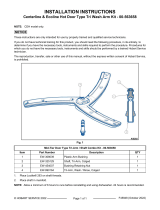
2. Install shroud baffle (Fig. 8) into ceiling, under the
evaporator, using 10-32 x 0.5" hex screws in 2
places.
Fig. 8
3. Install exhaust grill (Fig. 9) onto ceiling (under the
evaporator assembly) and to shroud baffle, using
10-32 x 0.5" hex screws in 9 places.
Fig. 9
PW Series Proofer and RPW Series Proofer/Retarder Installation Instructions - UNASSEMBLED CABINETS
F45826 Rev. B (1022) Page 14 of 34

FLOOR / FLOOR ANGLE
1. Install rear corner trim (1, Fig. 10) at both rear
corners of cabinet by applying NSF approved
silicone to back of trim and placing it snuggly
against side wall and back wall (2, Fig. 10). The
silicone will hold trim in place.
Fig. 10
2. Secure jamb trim (1, Fig. 11) to door jambs (2,
Fig. 11) by applying silicone to back of jamb trim
pieces, and placing one at the bottom of each
side of door opening.
Fig. 11
WITHOUT FLOOR
NOTE: Before proceeding, make sure cabinet is
square and level. Check door opening measurement
is correct, and is the same from top to bottom.
1. Set floor angles (Fig. 12), so that flanges with
holes are against bakery floor.
Fig. 12
2. Mark holes on the floor, then remove angles.
3. Mark 3/8" masonry drill bit 1.25" from tip end with
tape.
NOTE: 1.25" is the maximum depth for holes to be
drilled.
4. Drill each marked location to the 1.25" depth.
5. Vacuum all debris from the drilled holes.
6. Place an anchor from the floor anchor
package(s) into each hole, with the slotted end
inserted first.
NOTE: All anchors should sit 1/4" below the bakery
floor surface.
7. To set each anchor, drive the anchor setting tool
(see SPECIAL TOOLS) into the anchor until the
shoulder of the tool comes into contact with top
of anchor.
8. Clean all debris from the bakery floor where the
floor angles will be placed.
9. Apply NSF approved silicone to both flanges of
each floor angle in a zigzag pattern, and spread
out evenly with trowel.
PW Series Proofer and RPW Series Proofer/Retarder Installation Instructions - UNASSEMBLED CABINETS
Page 15 of 34 F45826 Rev. B (1022)

10. Place floor angles in position and secure to
bakery floor with hardware in the floor anchor
hardware package(s).
NOTE: There are three different lengths of screws in
the floor anchor hardware package(s). Select the
correct length screws that will allow angle to be
secured tightly against the floor.
11. Make sure all edges and holes are sealed with
NSF approved silicone. Clean up any excess
silicone.
12. Proceed to DOOR JAMB RETAINERS for next
steps.
WITH FLOOR
NOTE: Before proceeding, make sure cabinet is
square and level. Check door opening measurement
is correct, and is the same from top to bottom. See
WALL, DUCT, & EVAPORATOR
CONFIGURATIONS for measurements.
1. Place floor section(s) in cabinet, starting with the
left side.
Fig. 13
Fig. 14
NOTE: Single-wide cabinets will have only a single
(one-piece) floor.
2. After placing section(s), mark all hole locations
on the bakery floor for each floor section.
3. Remove all floor section(s).
4. Mark 3/8" masonry drill bit 1.25" from tip end will
tape.
NOTE: 1.25" is the maximum depth for holes to be
drilled.
5. Drill each marked location to the 1.25" depth.
6. Vacuum all debris from the drilled holes.
7. Place an anchor from the floor anchor
package(s) into each hole, with the slotted end
inserted first.
NOTE: All anchors should sit 1/4" below the bakery
floor surface.
8. To set each anchor, drive the anchor setting tool
(see SPECIAL TOOLS) into the anchor until the
shoulder of the tool comes into contact with top
of anchor.
9. Clean all debris from the bakery floor where the
floor section(s) will be placed.
10. Apply NSF approved silicone in a zigzag pattern
to vertical flanges and bottom of left floor section,
and spread out evenly with trowel across the
entire surface.
11. Starting with the left floor section, place floor
section against left wall and lower into place.
Fig. 15
PW Series Proofer and RPW Series Proofer/Retarder Installation Instructions - UNASSEMBLED CABINETS
F45826 Rev. B (1022) Page 16 of 34

NOTE: Use care to not disturb previously installed
floor sections while placing additional sections.
12. Center floor section only: Apply NSF approved
silicone in a zigzag pattern to vertical flanges and
bottom of center floor section, and spread out
evenly with trowel across the entire surface.
NOTE: make sure silicone overlaps each floor
section.
13. Center floor section only: Lower center floor
section into place, and verify all holes along
overlapping floor section align properly.
14. Right floor section only: Apply NSF approved
silicone in a zigzag pattern to vertical flanges and
bottom of right floor section, and spread out
evenly with trowel across the entire surface.
NOTE: make sure silicone overlaps each floor
section.
15. Right floor section only: Lower right floor
section into place, and verify all holes along
overlapping floor section align properly.
16. In all hole locations except the two holes next to
each door jamb, secure floor section(s) in place
with screws from the floor anchor hardware
package(s).
NOTE: There are three different lengths of screws in
the floor anchor hardware package(s). Select the
correct length screws that will allow angle to be
secured tightly against the floor.
17. Make sure all edges and holes are sealed with
NSF approved silicone. Clean up any excess
silicone.
18. Proceed to DOOR JAMB RETAINERS for next
steps.
DOOR JAMB RETAINERS
NOTE: Door jamb retainers are used in cabinets with
floors and without floors. IMAGES show door jamb
retainer installation without floors.
1. Place one door jamb retainer (1, Fig. 16) against
the jamb trim in the center of the jamb.
NOTE: For cabinets with floors, align the countersunk
holes in retainer with holes in floor.
Fig. 16
2. Mark the jamb trim through center of each slot on
the jamb retainer, then remove retainer.
NOTE: When drilling through stainless steel, use
constant pressure and slow speed. The outer skin of
the jamb will be easier to drill than the inner skin.
3. Using a 1/8" drill bit, drill two holes marked in Step
2 through jamb trim and jamb skin.
4. Repeat steps 1 through 3 for other door jamb.
NOTE: For cabinets with floors, proceed to Step
10.
5. Loosely fasten retainers in place using #10-16 x
3/4" drill tip screws (1, Fig. 17).
Fig. 17
PW Series Proofer and RPW Series Proofer/Retarder Installation Instructions - UNASSEMBLED CABINETS
Page 17 of 34 F45826 Rev. B (1022)

NOTE: Before marking holes in bakery floor, ensure
that the cabinet walls are square, and the door(s) will
close properly.
6. Mark holes in bakery floor (2, Fig. 17), then
remove retainers.
7. Mark 3/8" masonry drill bit 1.25" from tip end with
tape.
NOTE: 1.25" is the maximum depth for holes to be
drilled.
8. Drill each marked location to the 1.25" depth.
9. Vacuum all debris from the drilled holes.
10. Place an anchor from the floor anchor
package(s) into each hole, with the slotted end
inserted first.
NOTE: All anchors should sit 1/4" below the bakery
floor surface.
11. To set each anchor, drive the setting tool (see
SPECIAL TOOLS) into the anchor until the
shoulder of the tool comes into contact with top
of anchor.
12. Clean all debris from the bakery floor where
retainers will be placed.
13. Apply NSF approved silicone to back of both
flanges on each jamb retainer.
14. Fasten jamb retainers in place on jamb using
#10-16 x 3/4" drill tip screws (previously used in
Step 5).
15. Use screws from floor anchor hardware
package(s) to secure retainers to bakery floor
(Fig. 18).
Fig. 18
NOTE: There are three different lengths of screws in
the floor anchor hardware package(s). Select the
correct length screws that will allow jamb retainers to
be secured tightly to the bakery floor.
16. Make sure all edges and holes are sealed with
NSF approved silicone. clean up any excess
silicone.
17. Proceed to FLOOR RETAINERS.
FLOOR RETAINERS
NOTE: Floor retainers are used in cabinets with floors
or without floors.
1. If not already done, peel back protective plastic
from walls, corners, and jambs. Remove
protective plastic from floor retainers before
securing them to walls.
2. Fasten floor retainer (Fig. 19) to walls using
#10-16 x 3/4" drill tip screws from hardware
package.
NOTE: Walls are predrilled for floor retainer
attachment.
Fig. 19
3. Seal all edges (Fig. 20) with NSF approved
silicone.
NOTE: Rear corner trim must be fully sealed prior to
installing floor trim.
PW Series Proofer and RPW Series Proofer/Retarder Installation Instructions - UNASSEMBLED CABINETS
F45826 Rev. B (1022) Page 18 of 34

Fig. 20
OUTER FLOOR TRIM
1. If not already done, peel back protective plastic
from outside of walls, corners, and jambs.
Fig. 21
2. Make sure the surface where the outer floor trim
will be attached is clean and free from oil.
3. Remove protective plastic from outer surface of
outer trim.
4. Remove protective strip from adhesive tape strip
on back of outer floor trim.
5. Place outer trim piece(s) against floor, then press
floor trim against proofer walls, corners, and
jambs.
HUMIDITY SENSOR BRACKET
1. In the left front corner of front ceiling panel next
to the door jamb, in the forwardmost hole, install
two 1.50" nylon snap bushings. Install one in the
inner ceiling skin, and one in the outer ceiling
skin.
2. Mount sensor bracket to ceiling panel using two
10-32 x 0.5" hex head screws.
Fig. 22
NOTE: Sensor will be installed later in SERVICE
ENTRANCE AND JUNCTION BOXES.
AIR DUCT ASSEMBLY
NOTE: Refer to WALL, DUCT, & EVAPORATOR
CONFIGURATIONS for air duct locations.
1. If not already done, remove protective plastic
from wall panels and ceiling panels where duct
will be mounted.
2. Install two 1/4-20 x 1/2" hex bolts into the
mounting holes in the ceiling panel(s).
3. Remove intake and intermediate panels for air
ducts.
4. Hang each duct from the two bolts in the ceiling
panel(s) using the keyway cutouts in the top of
air duct.
5. Make a note of which holes in the duct align with
the holes in ceiling.
NOTE: The duct in the front left corner has four 1-1/2"
holes in the ceiling above the duct. All other ducts
have three 1-1/2" holes in the ceiling panels above
them.
NOTE: PW3S 40"D and PW2S 120"D units do not
have precut ceiling access holes, and need to have
the holes drilled prior to air duct installation.
PW Series Proofer and RPW Series Proofer/Retarder Installation Instructions - UNASSEMBLED CABINETS
Page 19 of 34 F45826 Rev. B (1022)

6. PW3S 40"D and PW2S 120"D only: Cut holes
in ceiling.
NOTE: When drilling, use constant pressure and slow
speed.
A. Mark holes in ceiling through access holes
in top of air duct directly above both sets of
element wires and above spray nozzle
connection.
B. Remove air duct and cut holes into the
ceiling using 1.5" hole saw and arbor.
C. Proceed to Step 8.
7. Remove duct from ceiling hanger bolts.
8. Install 1-1/2" diameter hole plug into any ceiling
panel holes that will not be used above air duct.
NOTE: Do not plug the hole in ceiling that will be
directly above air duct.
9. Rehang air duct on hex bolts installed in Step 2.
10. Locate the four holes in the back of each air duct
(Fig. 23), and align them with the four threaded
inserts installed in wall panel(s) with 1/4-20 x 1/4"
hex bolts.
Fig. 23
11. Tighten ceiling hanger bolts to secure air duct to
ceiling panel(s).
12. Install 1.50" snap bushings into all available
holes in inner ceiling panel above air duct.
NOTE: If holes do not line up or need to be cleaned
out, a 1.5" hole saw may be used to remove excess
material. Drill from the top of the cabinet.
13. Route heating element wire harness through
right most hole in ceiling panel above air duct,
then route element wires through one of the two
holes with bushings.
14. Route both fan harnesses and the high limit
harness through the first hole to the left of the
hole through which the element wires were
routed.
15. Repeat above steps for all remaining ducts.
DRAIN CONNECTION
SINGLE DUCT ON A WALL
NOTE: Determine where the drain is going to be
located, and clean the insulation out of the routing
hole(s) in the front and/or rear corners.
1. Install drain tube with elbow from outside of
cabinet through hole in rear corner or front corner
- depending on location of facilities drain.
Fig. 24
NOTE: Make sure tubes are fully inserted into fittings.
2. Using pieces supplied in drain parts kit, connect
Push-to-Connect (PTC) coupler (1, Fig. 25) to
drain tube on bottom of the drain.
3. Insert 5" PVC tube (2, Fig. 25) into coupler.
4. Attach PTC elbow (3, Fig. 25) to other end of 5"
PVC tube.
PW Series Proofer and RPW Series Proofer/Retarder Installation Instructions - UNASSEMBLED CABINETS
F45826 Rev. B (1022) Page 20 of 34
1/35