
user manual
AMOS-5000
Fan-less, compact embedded
chassis kit for the EITX-3000
R
evision
1
.
00
1
00
-
11
0
3
2009
-
1
551

II
Copyright
Copyright © 2009 VIA Technologies Incorporated. All rights reserved.
No part of this document may be reproduced, transmitted, transcribed, stored in a
retrieval system, or translated into any language, in any form or by any means, electronic,
mechanical, magnetic, optical, chemical, manual or otherwise without the prior written
permission of VIA Technologies, Incorporated.
Trademarks
All trademarks are the property of their respective holders.
PS/2 is a registered trademark of IBM Corporation.
Disclaimer
No license is granted, implied or otherwise, under any patent or patent rights of VIA
Technologies. VIA Technologies makes no warranties, implied or otherwise, in regard to
this document and to the products described in this document. The information provided
in this document is believed to be accurate and reliable as of the publication date of this
document. However, VIA Technologies assumes no responsibility for the use or misuse of
the information in this document and for any patent infringements that may arise from the
use of this document. The information and product specifications within this document are
subject to change at any time, without notice and without obligation to notify any person
of such change.
VIA Technologies, Inc. reserves the right the make changes to the products described in
this manual at any time without prior notice.
Regulatory Compliance
FCC-A Radio Frequency Interference Statement
This equipment has been tested and found to comply with the limits for a class A digital
device, pursuant to part 15 of the FCC rules. These limits are designed to provide
reasonable protection against harmful interference when the equipment is operated in a
commercial environment. This equipment generates, uses, and can radiate radio
frequency energy and, if not installed and used in accordance with the instruction manual,
may cause harmful interference to radio communications. Operation of this equipment in a
residential area is likely to cause harmful interference, in which case the user will be
required to correct the interference at his personal expense.
Notice 1
The changes or modifications not expressly approved by the party responsible for
compliance could void the user's authority to operate the equipment.
Notice 2
Shielded interface cables and A.C. power cord, if any, must be used in order to comply
with the emission limits.
Battery Recycling and Disposal
Only use the appropriate battery specified for this product.
Do not re-use, recharge, or reheat an old battery.
Do not attempt to force open the battery.
Do not discard used batteries with regular trash.
Discard used batteries according to local regulations.
Tested To Comply
With FCC Standards
FOR HOME OR OFFICE USE

III
Safety Precautions
Do’s
o Always read the safety instructions carefully.
o Keep this User's Manual for future reference.
o All cautions and warnings on the equipment should be
noted.
o Keep this equipment away from humidity.
o Lay this equipment on a reliable flat surface before setting
it up.
o Make sure the voltage of the power source and adjust
properly 110/220V before connecting the equipment to the
power inlet.
o Place the power cord in such a way that people cannot
step on it.
o Always unplug the power cord before inserting any add-on
card or module.
o If any of the following situations arises, get the equipment
checked by authorized service personnel:
o The power cord or plug is damaged.
o Liquid has penetrated into the equipment.
o The equipment has been exposed to moisture.
o The equipment has not worked well or you cannot
get it work according to User's Manual.
o The equipment has dropped and damaged.
o The equipment has obvious sign of breakage.
Don’ts
o Do not leave this equipment in an environment
unconditioned or in a storage temperature above 60°C
(140°F). The equipment may be damaged.
o Do not leave this equipment in direct sunlight.
o Never pour any liquid into the opening. Liquid can cause
damage or electrical shock.
o Do not place anything over the power cord.
o Do not cover the ventilation holes. The openings on the
enclosure protect the equipment from overheating

IV
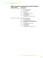
Box Contents and Ordering Information
Model Number Description
AMOS-5000-1MZZA1 Standard kit
1 x front I/O panel
1 x rear I/O panel
1 x top cover
1 x CF cover
1 x package of cable ties
1 x audio cable
1 x GPIO cable
1 x package of chassis screws
AMOS-5000-1MSZA1 Expanded storage kit
1 x front I/O panel
1 x rear I/O panel
1 x top half of storage chassis
1 x bottom half of storage chassis
1 x CF cover
1 x package of cable ties
1 x audio cable
1 x GPIO cable
1 x package of chassis screws

V
T
ABLE OF
C
ONTENTS
1 Overview ................................................................................................................. 1
Specifications ......................................................................................................... 4
Operating Environment................................................................................... 5
2 Installing the I/O cables.................................................................................. 6
Front I/O plate cables ....................................................................................... 7
Installing the GPIO cable............................................................................ 7
Installing the WLAN antenna .................................................................. 9
Rear I/O plate cables........................................................................................10
Installing the TRS audio cable ................................................................10
Installing the USB I/O cable....................................................................11
Installing the LPT cable..............................................................................12
3 Installing the standard kit ..............................................................................14
Installing the front I/O plate.........................................................................15
Installing the rear I/O plate...........................................................................17
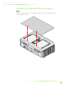
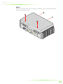
Installing the top cover ...................................................................................19
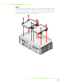
Installing the hard drive ............................................................................19
Installing the WLAN module..................................................................20
Installing the top cover..............................................................................21
4 Installing the expanded storage kit ..........................................................23
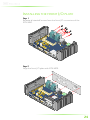
Installing the front I/O plate.........................................................................24
Installing the rear I/O plate...........................................................................26
Installing the expanded storage kit...........................................................28
Installing the WLAN module..................................................................28
Installing the bottom half of the storage kit....................................29
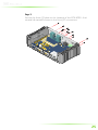
Installing the hard drives ..........................................................................31
Installing the top half of the storage kit.............................................33

1
1
Overview

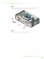
2
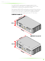
The AMOS-5000 is a fanless and compact chassis kit that
complements the EITX-3000. The AMOS-5000 comes in two
configurations: standard and expanded storage.
The standard AMOS-5000 configuration consists of front and rear
I/O plates and a top cover. The expanded storage configuration
consists of front and rear I/O plates and a compartmentalized
storage section that can support up to two 2.5” disk drives.

3
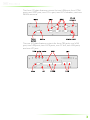
The front I/O plate features cutouts for two USB ports, four COM
ports, one GPIO port, one DC-in port, two LED indicators, and one
WLAN antenna.
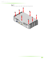
The rear I/O plate features cutouts for three TRS jacks, one VGA
port, two USB ports, two LVDS ports, one CF slot, two LAN ports,
and one LPT port.

4
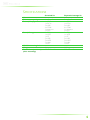
SPECIFICATIONS
Standard kit Expanded storage kit
Material
Heavy duty steel Heavy duty steel
Disk drive capacity
1 2
Front I/O support
1 x GPIO
1 x DC-in
2 x USB
4 x COM
1 x antenna
2 x LED
1 x GPIO
1 x DC-in
2 x USB
4 x COM
1 x antenna
2 x LED
Rear I/O support
3 x TRS jack
1 x VGA
1 x CF
2 x USB
2 x LVDS
2 x LAN
1 x LPT
3 x TRS jack
1 x VGA
1 x CF
2 x USB
2 x LVDS
2 x LAN
1 x LPT
WLAN mounting holes
Yes Yes
Weight
0.4 kg 0.75 kg
Dimensions (w x h x d)
(after assembly)
232 x 53 x 126 mm 232 x 73 x 126 mm

5
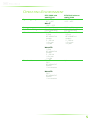
OPERATING ENVIRONMENT
EITX-3000 with
AMOS-5000
EITX-3000 without
AMOS-5000
Operating temperature
With HDD
With HDDWith HDD
With HDD
0°C ~ 45°C
With CF
With CFWith CF
With CF
-20°C ~ 55°C
With CF
With CFWith CF
With CF
-10°C ~ 65°C
Storage temperature
-20°C ~ 65°C -20°C ~ 65°C
Relative humidity
0% ~ 90% @ 45°C
(non-condensing)
10% ~ 90% @ 45°C
(non-condensing)
Vibration resistance
With CF
With CFWith CF
With CF
5 Grms
IEC 60068-2-64
random
5 – 500 Hz
1 Oct./min
1 hr/axis
With HDD
With HDDWith HDD
With HDD
1 Grms
IEC 60068-2-64
random
5 – 500 Hz
1 Oct./min
1 hr/axis
With CF
With CFWith CF
With CF
5 Grms
IEC 60068-2-64
random
5 – 500 Hz
1 Oct./min
1 hr/axis
Shock resistance
With CF
With CFWith CF
With CF
50 G
IEC 60068-2-67
half size
11 ms duration
With HDD
With HDDWith HDD
With HDD
20 G
IEC 60068-2-67
half size
11 ms duration
N/A

6
2
Installing the
I/O cables

7
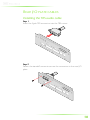
FRONT I/O PLATE CABLES
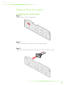
Installing the GPIO cable
Step 1
Step 1Step 1
Step 1
Break off the GPIO cutout filler.
Step 2
Step 2Step 2
Step 2
Use a metal file to smooth out any rough edges.
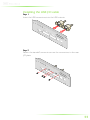
Step 3
Step 3Step 3
Step 3
Insert the 9-pin D-sub GPIO connector into the GPIO cutout.

8
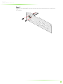
Step 4
Step 4Step 4
Step 4
Fasten the standoff screws to secure the connector to the front
I/O plate.

9
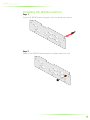
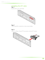
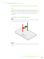
Installing the WLAN antenna
Step 1
Step 1Step 1
Step 1
Insert the WLAN antenna port into the antenna cutout.
Step
Step Step
Step 2
22
2
Fasten the WLAN antenna port in place with the nut.

10
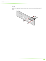
REAR I/O PLATE CABLES
Installing the TRS audio cable
Ste
SteSte
Step 1
p 1p 1
p 1
Insert the 3-jack TRS connector into the TRS cutout.
Step
Step Step
Step 2
22
2
Fasten the standoff screws to secure the connector to the rear I/O
plate.

11
Installing the USB I/O cable
Step 1
Step 1Step 1
Step 1
Insert the USB connectors into the USB cutouts.
Step
Step Step
Step 2
22
2
Fasten the standoff screws to secure the connectors to the rear
I/O plate.

12
Installing the LPT cable
Step 1
Step 1Step 1
Step 1
Break off the LPT cutout filler.
Step 2
Step 2Step 2
Step 2
Use a metal file to smooth out any rough edges.
Step 3
Step 3Step 3
Step 3
Insert the 25-pin D-sub LPT connector into the LPT cutout.

13
St
StSt
Step 4
ep 4ep 4
ep 4
Fasten the standoff screws to secure the connector to the rear I/O
plate.

14
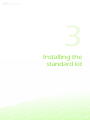
3
Installing the
standard kit

15
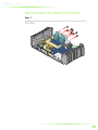
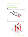
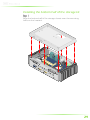
INSTALLING THE FRONT I/O PLATE
Step 1
Step 1Step 1
Step 1
Remove all standoff screws from the front I/O connectors of the
EITX-3000.
Page is loading ...
Page is loading ...
Page is loading ...
Page is loading ...
Page is loading ...
Page is loading ...
Page is loading ...
Page is loading ...
Page is loading ...
Page is loading ...
Page is loading ...
Page is loading ...
Page is loading ...
Page is loading ...
Page is loading ...
Page is loading ...
Page is loading ...
Page is loading ...
Page is loading ...
-
 1
1
-
 2
2
-
 3
3
-
 4
4
-
 5
5
-
 6
6
-
 7
7
-
 8
8
-
 9
9
-
 10
10
-
 11
11
-
 12
12
-
 13
13
-
 14
14
-
 15
15
-
 16
16
-
 17
17
-
 18
18
-
 19
19
-
 20
20
-
 21
21
-
 22
22
-
 23
23
-
 24
24
-
 25
25
-
 26
26
-
 27
27
-
 28
28
-
 29
29
-
 30
30
-
 31
31
-
 32
32
-
 33
33
-
 34
34
-
 35
35
-
 36
36
-
 37
37
-
 38
38
-
 39
39


Ask a question and I''ll find the answer in the document
Finding information in a document is now easier with AI
Related papers
-
VIA Technologies AMOS-5210 Quick Manual
-
-
VIA Technologies AMOS-5002-1D10A1 User manual
-
-
-
-
-
-
-
Other documents
-
AMD FM2+ Installation Instructions Manual
-
Dell OptiPlex 3070 User manual
-
Intel Ethernet Switch Boards User manual
-
Dell Embedded Box PC 3000 User guide
-
Asus RS260-E4 RX8 User manual
-
ASROCK X570 Phantom Gaming X User manual
-
Asus DSBV-DX User manual
-
Bull R425-E2 Installation and User guide
-
Supermicro A2SAP-L User manual
-
 Acrosser Technology AND-DNV3N1-02 User manual
