Page is loading ...


The following copyright notice protects this book under Copyright laws which prohibit such actions as, but not limited
to, copying, distributing, modifying, and making derivative works.
Copyright © Bull SAS
2010
Copyright © Super Micro Computer, Inc., 2009
Printed in France
Trademarks and Acknowledgements
We acknowledge the rights of the proprietors of the trademarks mentioned in this manual.
All brand names and software and hardware product names are subject to trademark and/or patent protection.
Quoting of brand and product names is for information purposes only and does not represent trademark misuse.
Intel® and Xeon® are registered trademarks of Intel Corporation.
Windows® and Microsoft® software are registered trademarks of Microsoft Corporation.
Linux® is a registered trademark of Linus Torwalds.
Phoenix® is a registered trademark of Phoenix Technologies.
The information in this document is subject to change without notice. Bull will not be liable for errors
contained herein, or for incidental or consequential damages in connection with the use of this material.

iii
Preface
Preface
About This Manual
This manual is written for professional system integrators and PC technicians. It
provides information for the installation and use of the bullx R425-E2.
Installation and maintenance should be performed by experienced technicians
only.
The bullx R425-E2 is a high-end server based on 4U rackmount or tower chassis
and the bullx R425-E2 motherboard, a dual processor serverboard that supports two
full-width Intel QuickPath Interconnect (QPI) @ 6.4GT/s with a total of up to 51.2
GB/s Data Transfer Rate (6.4 GB/s per direction) and up to 18 (144 GB) 240-pin
DIMM of DDR3 Reg. 1333/1066/800 MHz memory modules.
Manual Organization
Chapter 1: Introduction
The fi rst chapter provides a checklist of the main components included with the
ser-ver system and describes the main features of the bullx R425-E2 serverboard
and the chassis, which comprise the bullx R425-E2.
Chapter 2: Server Installation
This chapter describes the steps necessary to install the bullx R425-E2 into a rack
and check out the server confi guration prior to powering up the system. If your server
was ordered without processor and memory components, this chapter will refer you
to the appropriate sections of the manual for their installation.
Chapter 3: System Interface
Refer here for details on the system interface, which includes the functions and
information provided by the control panel on the chassis as well as other LEDs
located throughout the system.

bullx R425-E2 Installation and User's Guide
iv
Chapter 4: System Safety
You should thoroughly familiarize yourself with this chapter for a general overview
of safety precautions that should be followed when installing and servicing the
bullx R425-E2.
Chapter 5: Advanced Serverboard Setup
Chapter 5 provides detailed information on the bullx R425-E2 serverboard, includ-
ing the locations and functions of connections, headers and jumpers. Refer to this
chapter when adding or removing processors or main memory and when reconfi g-
uring the serverboard.
Chapter 6: Advanced Chassis Setup
Refer to Chapter 6 for detailed information on the bullx R425-E2 server chassis.
You should follow the procedures given in this chapter when installing, removing or
reconfi guring SATA or peripheral drives and when replacing system power supply
units and cooling fans.
Chapter 7: BIOS
The BIOS chapter includes an introduction to BIOS and provides detailed informa-
tion on running the CMOS Setup Utility.
Appendix A: BIOS Beep Error Codes
Appendix B: Adaptec HostRaid Setup Guidelines
Appendix C: System Specifi cations

v
Preface
Table of Contents
Chapter 1. Introduction
1-1 Overview .........................................................................................................1-1
1-2 Serverboard Features .....................................................................................1-2
CPU .................................................................................................................1-2
Memory ...........................................................................................................1-2
Chipset ............................................................................................................1-2
Expansion Slots .............................................................................................1-2
BIOS ................................................................................................................1-2
PC Health Monitoring ......................................................................................1-3
ACPI Features ............................................................................................... 1-3
Onboard I/O .................................................................................................... 1-4
Other ............................................................................................................... 1-4
1-3 Server Chassis Features ................................................................................1-5
Hard Drives .....................................................................................................1-5
Peripheral Drives .............................................................................................1-5
Backplane ........................................................................................................1-5
Fans ................................................................................................................ 1-5
Mounting Rails (optional) ................................................................................ 1-5
Power Supply ..................................................................................................1-5
Air Shroud ....................................................................................................... 1-6
Other Features ................................................................................................1-6
Chapter 2. Server Installation
2-1 Overview ............................................................................................................. 2-1
2-2 Unpacking the System .................................................................................... 2-1
2-3 Preparing for Setup .........................................................................................2-1
Choosing a Setup Location ............................................................................. 2-2
Rack Precautions ............................................................................................ 2-2
Server Precautions ..........................................................................................2-2
Rack Mounting Considerations .......................................................................2-3
Ambient Operating Temperature ................................................................ 2-3
Reduced Airfl ow .........................................................................................2-3
Mechanical Loading ...................................................................................2-3
Circuit Overloading .....................................................................................2-3
Reliable Ground ......................................................................................... 2-3
2-4 Installing the System into a Rack ...................................................................2-4
2-5 Checking the Serverboard Setup .................................................................... 2-8

vi
bullx R425-E2 Installation and User's Guide
2-6 Checking the Drive Bay Setup ...................................................................... 2-10
Chapter 3. System Interface
3-1 Overview .........................................................................................................3-1
3-3 Control Panel LEDs ........................................................................................3-2
3-2 Control Panel Buttons ..................................................................................... 3-2
3-4 Drive Carrier LEDs ..........................................................................................3-3
Chapter 4. System Safety
4-1 Electrical Safety Precautions .......................................................................... 4-1
4-2 General Safety Precautions ............................................................................ 4-2
4-3 ESD Precautions .............................................................................................4-3
4-4 Operating Precautions .................................................................................... 4-4
Chapter 5. Advanced Motherboard Setup
5-1 Motherboard Overview .................................................................................... 5-1
5-2 Handling the Motherboard ..............................................................................5-3
Precautions .....................................................................................................5-3
5-3 Connecting the Motherboard .......................................................................... 5-4
Connecting Data Cables ................................................................................. 5-4
Connecting Power Cables .............................................................................. 5-4
Connecting the Control Panel ......................................................................... 5-4
5-4 Back Panel Connectors/IO Ports .................................................................... 5-5
5-5 Installing the Processors and Heat Sinks .......................................................5-7
Installing an LGA 1366 Processor ................................................................. 5-7
Installing a CPU Heatsink .............................................................................. 5-9
Removing the Heatsink ........................................................................... 5-10
5-6 Installing Memory ...........................................................................................5-11
Memory Support .............................................................................................5-11
5-7 Adding PCI Add-On Cards ............................................................................5-13
5-8 Motherboard Details ...................................................................................... 5-14
bullx R425-E2 Motherboard Quick Reference ..............................................5-15
5-9 Back Panel Connector Pin Defi nitions .......................................................... 5-16
5-10 Front Control Panel .......................................................................................5-21
5-11 Connecting Cables .......................................................................................5-26
5-12 Jumper Settings ............................................................................................5-31
5-13 Onboard LED Indicators ...............................................................................5-35
5-14 Floppy, Serial ATA and SAS Connections .....................................................5-37
Chapter 6. Advanced Chassis Setup
6-1 Overview .........................................................................................................6-1
6-2 Installation Steps .............................................................................................6-1

vii
Table of Contents
6-3 Installation Step 1: Remove the Chassis Cover .............................................6-2
6-4 Installation Step 2: Confi gure the Storage Module ...................................... 6-4
6-5 Installation Step 3: Install Hard Drives..........................................................6-13
6-6 Installation Step 4: Install the Motherboard .................................................. 6-15
6-7 Installation Step 5: Install the Air Shroud...................................................... 6-21
6-8 System Fans .................................................................................................6-23
6-9 Power Supply ...............................................................................................6-25
Chapter 7. BIOS
7-1 Introduction ......................................................................................................7-1
7-2 Main Setup ......................................................................................................7-2
7-3 Advanced Setup Confi gurations......................................................................7-4
7-4 Security Settings ...........................................................................................7-26
7-5 Boot Confi guration ........................................................................................7-27
7-6 Exit Options ...................................................................................................7-29
Appendix A. BIOS Error Beep Codes
A-1 BIOS Error Beep Codes .................................................................................A-1
Appendix B. Adaptec HostRAID Setup Guidelines
Appendix C. System Specifi cations

Notes
viii
bullx R425-E2 Installation and User's Guide

Chapter 1. Introduction
1-1 Overview
The bullx R425-E2 is a high-end workstation comprised of two main subsystems:
A 4U rackmount or tower chassis and a dual Intel® Xeon processor serverboard.
Please refer to our web site for information on operating systems that have been
certifi ed for use with the bullx R425-E2 (www.bull.com).
In addition to the serverboard and chassis, various hardware components have
been included with the bullx R425-E2, as listed below:
One (1) SATA backplane (CSE-SAS-743TQ)
•
Three (3) 5000 RPM Hot-Swappable Cooling Fan (FAN-0074L4)•
Two (2) 5000 RPM Hot-Swappable Rear Exhaust Fan (FAN-0082L4)•
Eight (8) Black Hot-Swappable drive trays [CSE-PT17(B)]•
One (1) Air Shroud (CSE-PT0110)•
Two (2) CPU passive heat sinks (SNK-P0038P)•
One (1) SP801-1R 800W Power Supply (PWS-801-1R)•
Chapter 1: Introduction
1-1

1-2
bullx R425-E2 Installation and User's Guide
1-2 Serverboard Features
At the heart of the bullx R425-E2 lies the serverboard, a dual processor serverboard
based on the Intel 5500 chipset and designed to provide maximum performance.
Below are the main features of this serverboard (See Figure 1-1 on page 1-6 for a
block diagram of the 5500 chipset).
CPU
Two Intel•
®
5500 Series (LGA 1366) processors. Each processor supports two
full-width Intel QuickPath Interconnect (QPI) @6.4 GT/s with a total of up to 51.2
GB/s Data Transfer Rate (6.4 GB/s per direction)
Memory
18 240-pin DIMM sockets support up to 144 GB of DDR3 Reg. ECC •
1333/1066/800 MHz Memory modules (See Installing Memory on page 5-11
for DIMM Slot Population.)
Chipset
Intel 5520 chipset, including: two 5520 I/O Hubs (North Bridge) •
One ICH10R (South Bridge)•
Expansion Slots
Three PCI-E 2.0 x8 slots (Slot 1/Slot 3/Slot7)•
Two PCI-E 2.0 x16 slots (Slot 2/Slot 6)•
One PCI-E 2.0 x4 (in x8) slots (Slot 5)•
One PCI-E 2.0 x8 (in x16) slots (Slot 4)•
BIOS
32 Mb AMI SPI Flash ROM•
PCI 2.2, ACPI 1.0/2.0/3.0, Plug and Play (PnP), DMI 2.3, USB Keyboard sup-•
port, and SMBIOS 2.3

1-3
Chapter 1: Introduction
PC Health Monitoring
Onboard voltage monitors for CPU1 Vcore, CPU2 Vcore, 1.5V, 5V, 5VSB, 12V, •
-12V, 3.3Vcc, 3.3VSB, VBAT and Vtt
Fan status monitor with fi rmware control
•
CPU/chassis temperature monitors•
Platform Environment Control Interface (PECI) ready•
Thermal Monitor 2 (TM2) support•
CPU fan auto-off in sleep mode•
CPU slow-down on temperature overheat•
Pulse Width Modulation (PWM) Fan Control •
CPU thermal trip support for processor protection, power LED•
Power-up mode control for recovery from AC power loss•
Auto-switching voltage regulator for CPU cores•
System overheat/Fan Fail LED Indicator and control•
Chassis intrusion detection•
System resource alert via Supero Doctor III•
ACPI Features
Slow blinking LED for suspend state indicator•
Main switch override mechanism•
ACPI Power Management•
Keyboard Wakeup from Soft-off •

1-4
bullx R425-E2 Installation and User's Guide
Onboard I/O
Intel ICH10R supports six SATA2 ports (with RAID0, RAID1, RAID10, RAID5 •
supported in the Windows OS Environment, and RAID0, RAID1, RAID10 for
Linux Platforms)
Intel 82576 Gigabit Ethernet controllers supports Giga-bit LAN1/2 ports
•
A PHY chip supports the Dedicated IPMI LAN (X8DAH+-F only)•
One VGA Port supported by the Winbond WPCM 450R BMC Controller•
PS/2 mouse/keyboard ports, one COM port and one Serial header•
Up to ten USB 2.0 (Universal Serial Bus) (six Backpanel USB Ports, and four •
Front Panel/Front Accessible USB connections)
Super I/O: Winbond W83627DHG
•
ALC 8830 Audio Controller supports 7.1 HD Audio with Line-in, Line-out and •
Microphone, Backpanel Audio and CD connections
Two Internal1394 headers
•
One EIDE Ultra DMA/100 bus master interface supports UDMA Mode 5 and •
PIO Mode 4
IPMI 2.0 with full KVM support (X8DAH+-F only)
•
Other
Console redirection•
Onboard Fan Speed Control by Thermal Management via BIOS•

1-5
Chapter 1: Introduction
1-3 Server Chassis Features
The bullx R425-E2 high performance chassis includes the following features:
Hard Drives
The bullx R425-E2 chassis features 8 slots for U320 SCSI or SAS/SATA drives.
These drives are hot swappables. Once setup correctly, these drives can be re-
moved without powering down the server. In addition, these drives support SAF-TE
(SCSI) and SES2 (SAS/SATA).
Peripheral Drives
Each bullx R425-E2 chassis provides three 5.25" Peripheral Drive Bays for Floppy
Drive, DVD-ROM/CD-ROM Drive, or additional hard drives.
Backplane
Each bullx R4525-E2 chassis comes with a 4U backplane. Depending on your order,
your backplane will accept SAS/SATA or SCSI.
Fans
The bullx R4525-E2 chassis accepts three system fans and two rear exhaust fans.
System fans for bullx R4525-E2 chassis are powered from the serverboard. These
fans are 4U high and are powered by 3-pin connectors.
Mounting Rails (optional)
The bullx R4525-E2 can be placed in a rack for secure storage and use. To setup
your rack, follow the step-by-step instructions included in this manual.
Power Supply
Each bullx R4525-E2 chassis model includes a high-effi ciency 80%+ low noise
power supply with thermal control fan, rated at 200 Watts. In the unlikely event your
power supply fails, replacement is simple and can be done without tools.
Air Shroud

1-6
bullx R425-E2 Installation and User's Guide
Figure 1-1. Intel 5520 Chipset: System Block Diagram
Note: This is a general block diagram. Please see Chapter 5 for details.
Air shrouds are shields, usually plastic, that funnel air directly to where it is needed.
Always use the air shroud included with your chassis.
Other Features
Other onboard features are included to promote system health. These include
various four cooling fans, a convenient power switch, reset button, and 5 LED
indicators..

Chapter 2: Server Installation
2-1
Chapter 2. Server Installation
2-1 Overview
This chapter provides a quick setup checklist to get your bullx R425-E2 up and
running. Following these steps in the order given should enable you to have the
system operational within a minimum amount of time. This quick setup assumes that
your system has come to you with the processors and memory preinstalled.
If your system is not already fully integrated with a serverboard, processors, system
memory etc., please turn to the chapter or section noted in each step for details on
installing specifi c components.
The bullx R425-E2 may be employed either as a tower or mounted in a rack as a 4U
rackmount chassis. If using it as a tower unit, please read the Server Precautions
in the next section and then skip ahead to Section 2-5.
2-2 Unpacking the System
You should inspect the box the system was shipped in and note if it was damaged
in any way. If the server itself shows damage you should fi le a damage claim with
the carrier who delivered it.
Decide on a suitable location for the bullx R425-E2. It should be situated in a clean,
dust-free area that is well ventilated. Avoid areas where heat, electrical noise and
electromagnetic fi elds are generated.
You will also need it placed near a grounded power outlet. Be sure to read the Rack
and Server Precautions in the next section
2-3 Preparing for Setup
The box the system was shipped in may include two sets of rail assemblies, two
rail mounting brackets and mounting screws needed for installing the system into
a rack (optional kit). Follow the steps in the order given to complete the installation
process in a minimum amount of time. Please read this section in its entirety before
you begin the installation procedure outlined in the sections that follow.

2-2
bullx R425-E2 Installation and User's Guide
Choosing a Setup Location
Leave enough clearance in front of the rack to enable you to open the front •
door completely (about 65 cm / 25 inches) and approximately 75 cm / 30 inches
of clearance in the back of the rack to allow for suffi cient airfl ow and ease in
servicing.
!
!
Warnings and Precautions!
This product is for installation only in a Restricted Access Location (dedicated •
equipment rooms, service closets and the like).
This product is not suitable for use with visual display work place devices
•
acccording to §2 of the the German Ordinance for Work with Visual Display
Units.
Rack Precautions
Ensure that the leveling jacks on the bottom of the rack are fully extended to •
the fl oor with the full weight of the rack resting on them.
In single rack installation, stabilizers should be attached to the rack. In multiple
•
rack installations, the racks should be coupled together.
Always make sure the rack is stable before extending a component from the
•
rack.
You should extend only one component at a time - extending two or more si-
•
multaneously may cause the rack to become unstable.
Server Precautions
Review the electrical and general safety precautions in Chapter 4.•
Determine the placement of each component in the rack • before you install the
rails.
Install the heaviest server components on the bottom of the rack fi rst, and then •
work up.
Use a regulating uninterruptible power supply (UPS) to protect the server from
•
power surges, voltage spikes and to keep your system operating in case of a
power failure.
Allow the hot plug SATA drives and power supply modules to cool before touch-•
ing them.
Always keep the rack's front door and all panels and components on the servers
•
closed when not servicing to maintain proper cooling.

Chapter 2: Server Installation
2-3
Rack Mounting Considerations
Ambient Operating Temperature
If installed in a closed or multi-unit rack assembly, the ambient operating temperature
of the rack environment may be greater than the ambient temperature of the room.
Therefore, consideration should be given to installing the equipment in an environ-
ment compatible with the manufacturer’s maximum rated ambient temperature
(Tmra): 10° to 35° C (50° to 95° F).
Reduced Airfl ow
Equipment should be mounted into a rack so that the amount of airfl ow required
for safe operation is not compromised.
Mechanical Loading
Equipment should be mounted into a rack so that a hazardous condition does not
arise due to uneven mechanical loading.
Circuit Overloading
Consideration should be given to the connection of the equipment to the power
supply circuitry and the effect that any possible overloading of circuits might have
on overcurrent protection and power supply wiring. Appropriate consideration of
equipment nameplate ratings should be used when addressing this concern.
Reliable Ground
A reliable ground must be maintained at all times. To ensure this, the rack itself
should be grounded. Particular attention should be given to power supply connec-
tions other than the direct connections to the branch circuit (i.e. the use of power
strips, etc.).

2-4
bullx R425-E2 Installation and User's Guide
2-4 Installing the System into a Rack
This section provides information on installing the system into a rack unit. Rack
installation requires the use of the optional rackmount kit. If the system has already
been mounted into a rack or if you are using it as a tower, you can skip ahead to
Sections 2-5 and 2-6. There are a variety of rack units on the market, which may
mean the assembly procedure will differ slightly. The following is a guideline for
installing the server into a rack with the rack rails provided in the rackmount kit.
You should also refer to the installation instructions that came with the rack unit
you are using.
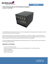
Identifying the Sections of the Rack Rails
The optional rackmount kit includes two rack rail assemblies. Each of these as-
semblies consist of three sections: an inner fi xed chassis rail that secures to the
chassis, an outer rack rail that secures directly to the rack itself and two rail brackets,
which also attack to the rack (see Figure 2-1.) The inner and outer rails must be
detached from each other to install. To remove the inner chassis rail, pull it out as
far as possible - you should hear a “click” sound as a locking tab emerges from
inside the rail assembly and locks the inner rail. Depress the locking tab to pull the
inner rail completely out. Do this for both assemblies (one for each side).
Figure 2-1.
Identifying the Sections of the Rack Rails
/