VIA Technologies EITX-3001 User manual
- Category
- Motherboards
- Type
- User manual

user manual
EITX-3001
Em-ITX Form Factor SBC
11
2
-
0
702
2012
-
105
0

II
Copyright and Trademarks
Copyright © 2010-2012 VIA Technologies Incorporated. All rights reserved.
No part of this document may be reproduced, transmitted, transcribed, stored in a
retrieval system, or translated into any language, in any form or by any means, electronic,
mechanical, magnetic, optical, chemical, manual or otherwise without the prior written
permission of VIA Technologies, Incorporated.
All trademarks are the property of their respective holders.
PS/2 is a registered trademark of IBM Corporation.
Disclaimer
No license is granted, implied or otherwise, under any patent or patent rights of VIA
Technologies. VIA Technologies makes no warranties, implied or otherwise, in regard to
this document and to the products described in this document. The information provided
in this document is believed to be accurate and reliable as of the publication date of this
document. However, VIA Technologies assumes no responsibility for the use or misuse of
the information in this document and for any patent infringements that may arise from the
use of this document. The information and product specifications within this document are
subject to change at any time, without notice and without obligation to notify any person
of such change.
Regulatory Compliance
FCC-A Radio Frequency Interference Statement
This equipment has been tested and found to comply with the limits for a class A digital
device, pursuant to part 15 of the FCC rules. These limits are designed to provide
reasonable protection against harmful interference when the equipment is operated in a
commercial environment. This equipment generates, uses, and can radiate radio
frequency energy and, if not installed and used in accordance with the instruction manual,
may cause harmful interference to radio communications. Operation of this equipment in a
residential area is likely to cause harmful interference, in which case the user will be
required to correct the interference at his personal expense.
Notice 1
The changes or modifications not expressly approved by the party responsible for
compliance could void the user's authority to operate the equipment.
Notice 2
Shielded interface cables and A.C. power cord, if any, must be used in order to comply
with the emission limits.
Battery Recycling and Disposal
Only use the appropriate battery specified for this product.
Do not re-use, recharge, or reheat an old battery.
Do not attempt to force open the battery.
Do not discard used batteries with regular trash.
Discard used batteries according to local regulations.
Tested To Comply
With FCC Standards
FOR HOME OR OFFICE USE

III
Safety Precautions
Do’s
o Always read the safety instructions carefully.
o Keep this User's Manual for future reference.
o All cautions and warnings on the equipment should be
noted.
o Keep this equipment away from humidity.
o Lay this equipment on a reliable flat surface before setting
it up.
o Make sure the voltage of the power source and adjust
properly 110/220V before connecting the equipment to the
power inlet.
o Place the power cord in such a way that people cannot
step on it.
o Always unplug the power cord before inserting any add-on
card or module.
o If any of the following situations arises, get the equipment
checked by authorized service personnel:
o The power cord or plug is damaged.
o Liquid has penetrated into the equipment.
o The equipment has been exposed to moisture.
o The equipment has not worked well or you cannot
get it work according to User's Manual.
o The equipment has dropped and damaged.
o The equipment has obvious sign of breakage.
Don’ts
o Do not leave this equipment in an environment
unconditioned or in a storage temperature above 70°C
(158°F). The equipment may be damaged.
o Never pour any liquid into the opening. Liquid can cause
damage or electrical shock.
o Do not place anything over the power cord.
o Do not cover the ventilation holes. The openings on the
enclosure protect the equipment from overheating

IV
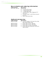
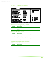
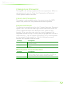
Box contents and ordering information
Model Number Description
EITX-3001-1N13A1 Standard kit
1 x EITX-3001 board
1 x Mini-jumper pack
1 x SATA data cable
1 x SATA power cable (Supports 2.5”
HDD only)
1 x Power cable, 2-pole Phoenix plug to
DC-Plug
USB to USB client cable
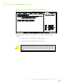
Optional accessories
Model Number Description
99G63-020186 AC-to-DC adapter, DC 19V/4.74A, 90W
with Phoenix Power Plug
99G33-02031C
Power cable, 180 cm, UK type
99G33-02032C
Power cable, 180 cm, USA type
99G33-02033C
Power cable, 180 cm, Europe type
99G33-02034C Power cable with PSE mark, 180 cm for
Japan market

V
T
ABLE OF
C
ONTENTS
1 Product Overview ............................................................................................... 1
Key Features ........................................................................................................... 2
Specifications ......................................................................................................... 3
EITX-3001 Dimensions ...................................................................................... 7
Top side ............................................................................................................... 7
Top side with heatsink ................................................................................. 8
Bottom side with heatsink ......................................................................... 8
Front I/O with heatsink ............................................................................... 9
Rear I/O with heatsink ................................................................................. 9
EITX-3001 Layout ............................................................................................... 10
Top side ............................................................................................................. 10
Bottom side ..................................................................................................... 10
Front I/O Layout ................................................................................................ 12
Power Button ................................................................................................. 12
Power Input Connector ............................................................................ 12
USB device port ............................................................................................. 12
COM Port Connectors ............................................................................... 13
LED Indicators ................................................................................................ 13
Rear I/O Layout .................................................................................................. 14
VGA Connector ............................................................................................ 14
HDMI
®
Port ...................................................................................................... 15
USB Port Connector .................................................................................... 15
LAN port: Gigabit Ethernet Port ........................................................... 16
Audio Ports (Line-out, Line-in and Mic-in) ........................................ 17
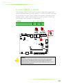
2 Onboard Connectors & Slots ...................................................................... 18
LVDS panel connector ................................................................................... 19
Resistive touch panel connector ................................................................ 20
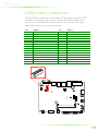
SATA Connector ................................................................................................ 21
SATA power connector ................................................................................. 22
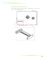
Compact Flash slot............................................................................................ 23
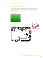
WLAN connector .............................................................................................. 24
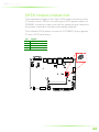
WLAN LED connector .................................................................................... 24
Keyboard and mouse pin header ............................................................. 25
COM3 and COM4 pin headers .................................................................. 26
Digital I/O pin header ..................................................................................... 27
SPI pin connector .............................................................................................. 28

VI
LPC connector .................................................................................................... 28
System Thermal Sensor pin header .......................................................... 29
System fan ............................................................................................................. 29
Battery ..................................................................................................................... 30
SODIMM SDRAM memory slot ................................................................... 31
3 Onboard Jumpers ............................................................................................ 33
LCD power select .............................................................................................. 34
COM3 and COM4 voltage select .............................................................. 35
AT/ATX Power mode Select ........................................................................ 36
System reset jumper ......................................................................................... 37
Clear CMOS jumper ......................................................................................... 38
4 BIOS Setup ............................................................................................................ 39
Entering the BIOS Setup Menu .................................................................. 40
Control Keys ......................................................................................................... 40
Getting Help ........................................................................................................ 41
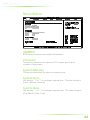
Main Menu ........................................................................................................... 42
AMIBIOS ............................................................................................................ 42
Processor .......................................................................................................... 42
System Memory ............................................................................................. 42
System Time .................................................................................................... 42
System Date .................................................................................................... 42
Advanced Settings ............................................................................................ 43
CPU Configuration ........................................................................................... 44
CMPXCHG8B instruction support ........................................................ 44
Nano CPU Thermal Monitor Adjust .................................................... 44
Thermal Monitor Bus Ratio ...................................................................... 45
Thermal Monitor Bus VID ........................................................................ 45
IDE Configuration ............................................................................................. 46
Parallel ATA IDE Controller ...................................................................... 46
Hard Disk Write Protect ............................................................................ 46
IDE Detect Time Out (Sec) ....................................................................... 46
ATA(PI) 80Pin Cable Detection ............................................................. 47
IDE Drives .............................................................................................................. 48
Type..................................................................................................................... 48
LBA/Large Mode .......................................................................................... 48
Block (Multi-Sector Transfer).................................................................... 48
PIO Mode ......................................................................................................... 49
DMA Mode ..................................................................................................... 49
S.M.A.R.T. ........................................................................................................... 49
32Bit Data Transfer ...................................................................................... 49
SuperIO Configuration ................................................................................... 50
Serial Port Address, IRQ, and Type ....................................................... 50
WATCH-DOG ................................................................................................ 50
Hardware Health Configuration ............................................................... 51

VII
H/W Health Function ................................................................................ 51
ACPI Settings ........................................................................................................ 52
General ACPI Configuration ........................................................................ 53
Suspend Mode .............................................................................................. 53
Repost Video on S3 Resume .................................................................. 53
Advanced ACPI Configuration ................................................................... 54
ACPI Version Features ............................................................................... 54
ACPI APIC Support ....................................................................................... 54
AMI OEMB Table .......................................................................................... 54
Headless Mode .............................................................................................. 54
Chipset ACPI Configuration ......................................................................... 55
USB Device Wakeup Function .............................................................. 55
APM Configuration ........................................................................................... 56
Power Management / APM ................................................................... 56
Power Button Mode ................................................................................... 56
Suspend Power Saving Type .................................................................. 56
Restore on AC / Power Loss ................................................................... 57
System Thermal ............................................................................................. 57
Standby Time Out ........................................................................................ 57
Suspend Time Out ....................................................................................... 57
Hard Disk Time Out (Minute) ................................................................. 57
Green PC Monitor Power State ............................................................. 58
Video Power Down Mode...................................................................... 58
Hard Disk Power Down Mode ............................................................. 58
Display Activity ............................................................................................... 58
Monitor IRQ3~15 ......................................................................................... 59
Resume on Ring ............................................................................................ 59
Resume on PME# ......................................................................................... 59
Resume On PS/2 KBC ................................................................................ 59
Wake-Up Key .................................................................................................. 59
Wake-Up Password..................................................................................... 60
Resume on PS/2 Mouse............................................................................ 60
Resume on RTC Alarm ............................................................................... 60
RTC Alarm Date (Days) .............................................................................. 60
System Time .................................................................................................... 60
Spread Spectrum Configuration ................................................................ 61
Spread Spectrum Configuration ........................................................... 61
USB Configuration ............................................................................................ 62
USB 1.1 Ports Configuration ................................................................... 62
USB 2.0 Ports Enable .................................................................................. 62
USB Device Mode Enable ........................................................................ 62
Legacy USB Support ................................................................................... 62
USB 2.0 Controller Mode ......................................................................... 63
BIOS EHCI Hand-Off ................................................................................... 63

VIII
FreeDos Configuration ................................................................................... 64
Advanced PCI/PnP Settings.......................................................................... 65
Clear NVRAM ................................................................................................. 65
Plug & Play O/S ............................................................................................. 65
PCI Latency Timer ......................................................................................... 65
Allocate IRQ to PCI VGA ........................................................................... 66
Palette Snooping .......................................................................................... 66
PCI IDE BusMaster ........................................................................................ 66
IRQ3~15 ........................................................................................................... 66
DMA Channel 0~7 ..................................................................................... 66
Reserved Memory Size ............................................................................... 66
Boot Settings ........................................................................................................ 67
Boot Settings Configuration ......................................................................... 68
Quick Boot ....................................................................................................... 68
Display Logo ................................................................................................... 68
AddOn ROM Display Mode.................................................................... 68
Bootup Num-Lock ....................................................................................... 68
PS/2 Mouse Support ................................................................................... 69
Wait For ‘F1’ If Error .................................................................................... 69
Hit ‘DEL’ Message Display ........................................................................ 69
Boot Device Priority .......................................................................................... 70
1st Boot Device ............................................................................................. 70
Security Settings.................................................................................................. 71
Change Supervisor Password ................................................................ 71
User Access Level ......................................................................................... 71
Change User Password ............................................................................ 72
Clear User Password ................................................................................... 72
Password Check............................................................................................ 72
Boot Sector Virus Protection ................................................................... 72
Advanced Chipset Settings ........................................................................... 73
North Bridge VIA VX855 Configuration ................................................ 74
OnChip VGA Configuration ........................................................................ 75
VGA Frame Buffer Size .............................................................................. 75
CPU Direct Access Frame Buffer .......................................................... 75
Select Display Device .................................................................................. 75
Panel Type ....................................................................................................... 76
Dithering .......................................................................................................... 76
South Bridge VIA VX855 Configuration ................................................ 77
PATA Channel Enable ............................................................................... 77
High Definition Audio................................................................................ 77
PCI Delay Transaction ................................................................................ 77
Exit Options .......................................................................................................... 78
Save Changes and Exit .............................................................................. 78
Discard Changes and Exit ........................................................................ 78

IX
Discard Changes .......................................................................................... 78
Load Optimal Defaults ............................................................................... 78
5 Driver Installation ............................................................................................... 79
Microsoft Driver Support ................................................................................ 80
Linux Driver Support ........................................................................................ 80
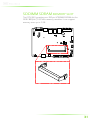
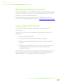
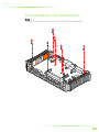
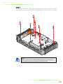
A Disassembling the EITX-3001 Board from Heatsink ........................ 81
Disassembling the mainboard .................................................................... 82
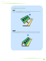
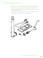
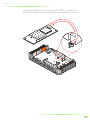
B Installing the WLAN module ....................................................................... 85
Installing the WLAN USB module ............................................................. 86

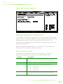
1
1
Product Overview

2
The VIA EITX-3001 is a high performance single board computer
(SBC) with low power requirements based on the Embedded ITX
(Em-ITX) form factor. Its low power requirements are made
possible by its usage of energy efficient VIA Nano CPU.
The EITX-3001 is designed for ultra-thin embedded applications
and can withstand temperatures ranging from -10°C to 60°C. The
powerful VIA Nano processor and VIA VX855 media system
processor are placed on the bottom side of the board, enabling
an efficient space-saving design that easily accommodates quiet
and passive cooling thermal solutions.
The EITX-3001 includes an onboard DC-to-DC converter that
supports both AT and ATX power modes. The power converter
can support a wide range of power input voltage from DC 7V to
DC 36V and can be configured through an onboard switch.
With generous support for multiple display options, the EITX-3001
is ideally suited for high-end multimedia applications including
POS, kiosks, ATM, HMI, factory automation, POI, and digital
signage. The dual I/O coastline design of the EITX-3001 provides
ample space for multiple ports such as one HDMI
®
port, one VGA
port, one Gigabit Ethernet port, four USB 2.0 ports, two RS-232
COM ports, and two RS-232/422/485 configurable COM ports.
KEY FEATURES
• Onboard VIA Nano processor (1MB L2 Cache)
Em-ITX (Embedded ITX) form factor with 17cm (W) x 12 cm (L)
• Dual-side multiple I/O connector-coastlines
• Integrated VIA C-9 HCM, DX9 3D/2D graphics & video
processor with MPEG-2, WMV9, VC1, and H.264 video
decoding acceleration
• Display interface: Supports one VGA, one 24-bit single
channel LVDS, and one HDMI
®
port
• Onboard one Gigabit Ethernet
• Onboard two RS-232 and two RS-232/422/485
• Onboard five USB 2.0 host ports and one USB device port
• Supports 5-wire/4-wire resistive touch interface connector
• Fan-less and ultra low power consumption

3
SPECIFICATIONS
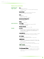
Processor Core
Logic System
CPU
• VIA Nano Processor
• Compact 21 mm x 21 mm NanoBGA2 package
• Nano 1.3 GHz
System Chipset
• VIA VX855 Unified Digital Media IGP chipset
• Supports 800 MHz Front Side Bus
BIOS
• AMI BIOS
• 8Mbit SPI Flash BIOS
•Supports Plug & Play, APM 1.2
System Power Management
• Times Power On
• ACPI Supported
Battery
• Lithium 3V/48mAh
System
Memory
Technology
• One 200-pin SODIMM Socket support DDR2
800/667/533 SDRAM
Maximum Capacity
• Support memory sizes up to 2 GB
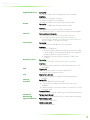
Graphic
Controller
• Integrated VIA C-9 HCM DX9 3D/2D graphics & video
processor, built-in Unified Video Decoding Accelerator,
supports MPEG-2, WMV9/VC1, and H.264 video
decoding acceleration
Display Memory
• Optimized Unified Memory Architecture (UMA), supports
up to 512 MB frame buffer using system memory
CRT Interface
• Onboard one VGA connector
• Pixel resolution support up 1920 x 1440 (VGA)
LVDS Interface
• Supports 1 x 24-bit single-channel LVDS interface with
inverter control signals by an onboard 2 x 15-pin wafer
box connector
• Up to WXGA 1366 x 768 panel resolution
• Onboard 5V/3.3V LCD power switch (default at 3.3V)
HDMI
®
Interface
• AD 9389B HDMI
®
transmitter
• Onboard 1 x dual-link HDMI
®
connector with flange
Dual Independent Display
• Supports CRT + LVDS, CRT+HDMI and LVDS + HDMI at
same time resolutions, same pixel depths, and same
refresh rates

4
Gigabit Ethernet
Controller
• Onboard VIA VT6122 Gigabit Ethernet controller
Interface
• Supports one RJ45 connector
• Supports Wake On LAN (WOL)
• Support Preboot Execution Environment (PXE)
Audio
Controller
• VIA VT1708B High Definition Audio Codec
Interface
• Support Line-in, Line-out, Mic-in connectors
• Onboard TI TPA1517 6-W stereo audio power amplifier
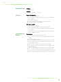
USB 2.0
Onboard
Five
USB port
s
• Four USB ports by a pair of mini-DIN connector
• Two USB ports by a pin headers with support of
individual VCC power (one USB port is reserved for use
with the EMIO-1530 WLAN module)
Serial Ports
Controller
• Onboard Fintek F81865 LPC I/O controller
Interface
• Support 4 COM ports
• Two RS232/422/485 by two DB-9 connectors (COM
1 and COM 2), configurable via BIOS setup. Supports
RS-485 AutoFlow control functions
• Two RS-232 by two 2x5-pin headers (COM 3 and
COM 4)
Resistive Touc
h
Controller
• EETI ETP-CP-S5XU resistive touch panel controller
Interface
• 1 x 5-wire/4-wire resistive touch sensor interface by a 1 x 5-
pin header
D
IO
Digital
I/O
• One 2x6-pin header to support 8-bit GPIO
• Support 5V/12V power source
PS2
Key
board & Mouse
• One 2x5-pin header to support PS2 keyboard/mouse
interface
Storage
Interface
Serial ATA
• JMicron JMH330 SATA controller
• 1 x SATA II port, maximum data transfer rate up to
300MB/s
• Onboard power connector output 5V support 2.5" SATA
hard disk drive
CompactFlash
• Onboard one socket support type I/II CompactFlash disk
Hardware
Monitoring
Temperature Sensor
• Built-in one Thermal Sensor by a 1x3-pin header onboard
System Indicator
Power Status LED
• One green color LED
HDD Activity LED
• One red color LED

5
Watchdog Timer
Output
• System reset
Interval
• Programmable 1~255 sec.
I/O
ports
Front I/O coastline
• One HDD & PWR LED
• Two RS-232/422/485 COM port connectors as COM 1
and COM2
• One USB device port
• One 2-pole of Phoenix power input connector
• One ATX power On/Off switch
Rear I/O coastline
• One VGA connector
• One dual-link HDMI
®
connector with flange
• Four USB 2.0 host port by 2 pairs of double mini-DIN
connector
• One RJ45 connector for Gigabit Ethernet connector
• Three 3.5Φ audio jacks
Onboard I/O pin
headers
Pin
-
headers
• Two 2 x 5-pin headers for two RS-232
• Two 1 x 3-pin headers for 5V/12V selection of COM3 and
COM4
• One SATA data connector
• One SATA power connector support of 5V for 2.5” HDD
• One 2 x 6-pin header support 8-bit GPIO, with 5VDC and
12VDC power source
• One 1 x 3-pin header for thermal sensor as SEN1
• One 1 x 6-pin header for connection with VIA EMIO-1530
wireless LAN card
• One 2 x 15-pin header for signal channel LVDS interface
• One 1 x 3-pin header for LCD Power 3.3v/5V selection
• One 2 x 5-pin header support PS2 keyboard/mouse interface
• One 1 x 3-pin header for selecting the AT or ATX mode

6
Onboard
DC to DC Power
Supply
Po
wer Consumption
• Typical 18.5W
Input Voltage
• Built-in onboard DC-to-DC converter
• Accept wide range of Power Input of DC 7V ~ 36V
• Supports AT and ATX mode
Power Input Connector
• One 2-pole Phoenix connector
AT/ATX
• Onboard AT/ATX switch by a 1x3-pin headers
Fuse Rating
• 7A / 125V
Physical
Characteristics
Form Factor
• Em-ITX
Board Dimension (W x L)
• 17 cm (W) x 12 cm (L)
Weight
• 1 kg (net weight of board plus heatsink only)
Heatsink
Construction
• Aluminum Alloy mixed with Copper Heatsink
Dimension (W x H x D)
• 230.45 mm x 34 mm x 124.8 mm
Environment
Specifications
Operating
Temperature
• -10 to 60° C
Storage Temperature
• -20 to 70° C
Operating Humidity
• 10% ~ 90%, relative humidity, non-condensing

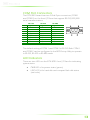
7
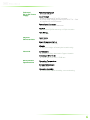
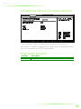
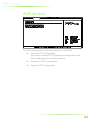
EITX-3001 DIMENSIONS
Top side

8
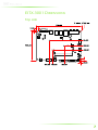
Top side with heatsink
Bottom side with heatsink

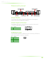
9
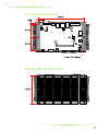
Front I/O with heatsink
Rear I/O with heatsink

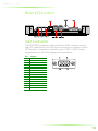
10
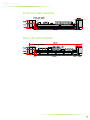
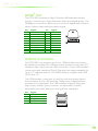
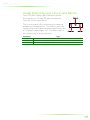
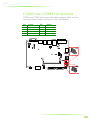
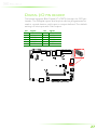
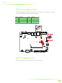
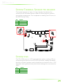
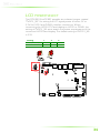
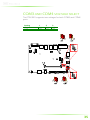
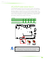
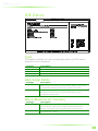
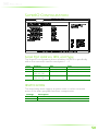
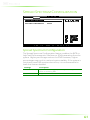
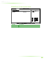
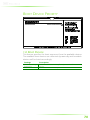
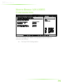
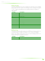
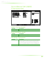
EITX-3001 LAYOUT
Top side
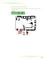
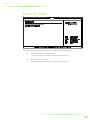
Bottom side

11
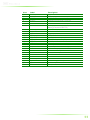
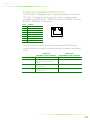
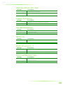
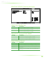
Item
Label
Description
1
FAN1
System Fan Power connector
2
JK
B/MS1
PS/2 keyboard and mouse pin header
3
JPVDD1
PVDD1 LCD power select jumper
4
JLVDS1
Onboard LVDS Panel connector
5
JWLAN1
WLAN connector
6
JWLAN
-
LED1
WLAN LED status indicator pin header
7
BAT1
Battery socket for
Lithium 3V/48mAh
coin
battery (Panasonic BR1225)
8
JCLEAR_CMOS1
Clear CMOS jumper
9
TP_+3V3SATA1
SATA1 connector
10
DIO1
Digital I/O pin
header
11
JSPI1
JSPI pin
header
12
JPW
-
OUT1
Internal power output pin header
13
JCOMV3
COM3 voltage select jumper
14
JCOM3
COM3 pin header
15
JC
OMV4
COM4 voltage select jumper
16
JCOM4
COM4 pin header
17
JAT/ATX1
AT/ATX power mode select
jumper
18
JRST1
System reset jumper
19
DIM1
SODIMM memory slot
20
SEN1
Thermal sensor
pin header
21
S
-
POWER1
SATA
-
Power
1
connector
22
JLPC1
LPC connector
23
TOUCH_R1
Resistive Touch connector
24
U5
VIA VX8
55
system chipset
25
U2
VIA Nano CPU
26
CF1
Compact Flash socket
Page is loading ...
Page is loading ...
Page is loading ...
Page is loading ...
Page is loading ...
Page is loading ...
Page is loading ...
Page is loading ...
Page is loading ...
Page is loading ...
Page is loading ...
Page is loading ...
Page is loading ...
Page is loading ...
Page is loading ...
Page is loading ...
Page is loading ...
Page is loading ...
Page is loading ...
Page is loading ...
Page is loading ...
Page is loading ...
Page is loading ...
Page is loading ...
Page is loading ...
Page is loading ...
Page is loading ...
Page is loading ...
Page is loading ...
Page is loading ...
Page is loading ...
Page is loading ...
Page is loading ...
Page is loading ...
Page is loading ...
Page is loading ...
Page is loading ...
Page is loading ...
Page is loading ...
Page is loading ...
Page is loading ...
Page is loading ...
Page is loading ...
Page is loading ...
Page is loading ...
Page is loading ...
Page is loading ...
Page is loading ...
Page is loading ...
Page is loading ...
Page is loading ...
Page is loading ...
Page is loading ...
Page is loading ...
Page is loading ...
Page is loading ...
Page is loading ...
Page is loading ...
Page is loading ...
Page is loading ...
Page is loading ...
Page is loading ...
Page is loading ...
Page is loading ...
Page is loading ...
Page is loading ...
Page is loading ...
Page is loading ...
Page is loading ...
Page is loading ...
Page is loading ...
Page is loading ...
Page is loading ...
Page is loading ...
Page is loading ...
Page is loading ...
-
 1
1
-
 2
2
-
 3
3
-
 4
4
-
 5
5
-
 6
6
-
 7
7
-
 8
8
-
 9
9
-
 10
10
-
 11
11
-
 12
12
-
 13
13
-
 14
14
-
 15
15
-
 16
16
-
 17
17
-
 18
18
-
 19
19
-
 20
20
-
 21
21
-
 22
22
-
 23
23
-
 24
24
-
 25
25
-
 26
26
-
 27
27
-
 28
28
-
 29
29
-
 30
30
-
 31
31
-
 32
32
-
 33
33
-
 34
34
-
 35
35
-
 36
36
-
 37
37
-
 38
38
-
 39
39
-
 40
40
-
 41
41
-
 42
42
-
 43
43
-
 44
44
-
 45
45
-
 46
46
-
 47
47
-
 48
48
-
 49
49
-
 50
50
-
 51
51
-
 52
52
-
 53
53
-
 54
54
-
 55
55
-
 56
56
-
 57
57
-
 58
58
-
 59
59
-
 60
60
-
 61
61
-
 62
62
-
 63
63
-
 64
64
-
 65
65
-
 66
66
-
 67
67
-
 68
68
-
 69
69
-
 70
70
-
 71
71
-
 72
72
-
 73
73
-
 74
74
-
 75
75
-
 76
76
-
 77
77
-
 78
78
-
 79
79
-
 80
80
-
 81
81
-
 82
82
-
 83
83
-
 84
84
-
 85
85
-
 86
86
-
 87
87
-
 88
88
-
 89
89
-
 90
90
-
 91
91
-
 92
92
-
 93
93
-
 94
94
-
 95
95
-
 96
96


VIA Technologies EITX-3001 User manual
- Category
- Motherboards
- Type
- User manual
Ask a question and I''ll find the answer in the document
Finding information in a document is now easier with AI
Related papers
-
VIA Technologies EITX-3000 User manual
-
-
-
-
-
-
-
VIA Technologies AMOS-5002-1D10A1 User manual
-
-
