Page is loading ...

STS
®
Steam-to-Steam Humidifier
Installation, Operation,
and Maintenance Manual
IMPORTANT: Read and save these instructions.
STS_IOM.pdf 1 1/20/2010 10:29:19 AM

1BHFt%3*45&&.454)VNJEJGJFS*OTUBMMBUJPO0QFSBUJPOBOE.BJOUFOBODF.BOVBM
ATTENTION INSTALLER
Read this manual before installing.
Leave manual with product owner.
DRI-STEEM
®
technical support
800-328-4447
WARNING!
Disconnect electrical power before installing supply wiring. Contact with
energized circuits can cause severe personal injury or death as a result
of electrical shock.
This product must be installed by qualified HVAC and electrical
contractors and in compliance with local, state, federal, and governing
codes. Improper installation can cause property damage, severe
personal injury, or death as a result of electric shock, burns, and/or fire.
The humidifier tank, dispersion assembly, and all connected hose or
piping can contain or discharge hot steam and/or hot water at 212 °F
(100 °C). Discharged steam is not visible. Contact with hot surfaces,
discharged hot water, or air into which steam has been discharged can
cause severe personal injury.
Failure to follow the instructions in this manual can cause moisture to
accumulate, which can cause bacteria and mold growth or dripping
water into building spaces. Dripping water can cause property damage;
bacteria and mold growth can cause illness.
Supply water pressure greater than 80 psi (550 kPa) can cause the
humidifier to overflow.
STS_IOM.pdf 2 1/20/2010 10:29:45 AM

%3*45&&.454)VNJEJGJFS*OTUBMMBUJPO0QFSBUJPOBOE.BJOUFOBODF.BOVBMt1BHF
5BCMFPGDPOUFOUT
Overview
STS models ............................................4
Dimensions ............................................5
Capacities and weights ...................................7
Installation
Selecting a location ......................................8
Mounting
Support legs .......................................10
Trapeze hanger ....................................10
H-legs ............................................11
Wall brackets ......................................11
Weather cover .........................................13
Outdoor enclosure .....................................15
Piping
Drain .............................................24
Standard water, one heat exchanger ..................27
DI water, two heat exchangers .......................28
Steam supply ......................................30
Wiring ...............................................31
Humidistat and transmitter placement ....................34
Dispersion
General instructions ................................35
Interconnecting piping requirements .................36
Drip tee installation ................................38
Overhead installation ...............................39
Single tube and multiple tube ........................40
Rapid-sorb ........................................45
Area-type fan ......................................53
Operation
Start-up procedure .....................................55
Maintenance
Water quality ..........................................59
Standard water models .................................60
DI water models .......................................63
Outdoor enclosure .....................................65
Troubleshooting
STS humidifier ........................................66
LW417 controller ......................................67
Replacement parts
Humidifier tank .......................................68
Control cabinet ........................................70
Outdoor enclosure .....................................71
Warranty
. ..............................................Back cover
STS_IOM.pdf 3 1/20/2010 10:29:45 AM

1BHFt%3*45&&.454)VNJEJGJFS*OTUBMMBUJPO0QFSBUJPOBOE.BJOUFOBODF.BOVBM
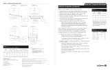
Figure 4-1:
STS models
STS standard water model
Standard water models (STS)
State-of-the-art technology in a simple, low-maintenance humidier.
is humidier is designed to be used with either soened or
unsoened tap water.
e standard water STS humidier requires water conductivity of at
least 100 μS/cm (2 grains/gallon) to operate. It will not operate with
water treated by reverse osmosis or deionization processes. However,
STS
humidiers are available for use with these water types. See
below.
Deionized water models (STS-DI)
e STS-DI, shown below, is designed specically for use with
deionized or reverse osmosis water.
Both models can be converted in the eld for use with soened/
unsoened tap water or deionized/reverse osmosis water.
Steam outlet
Air gap
Water seal
Condensate
return
Steam trap
Automatic
steam valve
Open drain
Manual drain
valve
Heat exchanger
Float valve
OM-939
Note: Drain piping material must be suitable for 212 °F (100 °C) water.
454NPEFMT
Steam outlet
Automatic
steam valve
To steam
supply
Steam trap
Condensate
return
Water seal
Air gap
Open drain
Manual drain or
optional motorized
drain valve
Heat exchanger
OM-938
Temperature
sensor
STS-DI water model
Note:
t %BNBHFDBVTFECZDIMPSJEFDPSSPTJPOJT
not covered by your DRI-STEEM
warranty.
Overview
STS_IOM.pdf 4 1/20/2010 10:29:45 AM

%3*45&&.454)VNJEJGJFS*OTUBMMBUJPO0QFSBUJPOBOE.BJOUFOBODF.BOVBMt1BHF
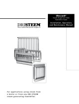
%JNFOTJPOT
Figure 5-2:
Dimensions, STS model 800 (with copper or stainless steel heat exchangers)
Front view
B
E
F
C
OM-936
Side view
H
G
J
A
D
L
K
M
Front view
5/16"
dia. (M8)
mounting
holes
B
A
E
H
D
C
OM-932OM-931
Side view
Figure 5-1:
Dimensions, STS models 25, 50, 100, 200 and 400 (with copper or stainless steel heat exchangers)
J
K
L
M
Note: See the dimension tables on the next page.
Note: See the dimension tables on the next page.
Overview
STS_IOM.pdf 5 1/20/2010 10:29:48 AM

1BHFt%3*45&&.454)VNJEJGJFS*OTUBMMBUJPO0QFSBUJPOBOE.BJOUFOBODF.BOVBM
%JNFOTJPOT
Table 6-2:
STS dimensions with stainless steel heat exchangers
Description
STS model numbers
25S 50S 100S 200S 400SNC** 800SNC**
inches mm inches mm inches mm inches mm inches mm inches mm
A Height* 19.50 495 19.50 495 19.50 495 19.50 495 19.50 495 29.75 756
B Width 14.75 375 14.75 375 19.25 489 30.25 768 30.25 768 30.25 768
C Length 23.65 600 39.65 1007 39.65 1007 55.15 1401 55.15 1401 55.15 1401
D
Distance from bottom to supply
inlet of first heat exchanger
6.85 174 6.85 174 6.85 174 6.85 174 6.85 174 6.85 174
E
Distance from bottom to return
outlet of first heat exchanger
3.35 85 3.35 85 3.35 85 3.35 85 3.35 85 3.35 85
F
Distance from bottom to supply
inlet of second heat exchanger
——————————14.5 368
G
Distance from bottom to return
outlet of second heat exchanger
——————————11.0 279
H
Distance from side to heat
exchanger
3.25 83 3.25 83 3.25 83 3.25 83 3.25 83 3.25 83
J Pressurized steam supply inlet
¾" pipe
thread
DN20
1" pipe
thread
DN25
1" pipe
thread
DN25
1½" pipe
thread
DN40
1½" pipe
thread
DN40
1½" pipe
thread
DN40
K Pressurized steam return outlet
¾" pipe
thread
DN20
¾" pipe
thread
DN20
¾" pipe
thread
DN20
¾" pipe
thread
DN20
¾" pipe
thread
DN20
¾" pipe
thread
DN20
L
Distance from side to steam
vapor outlet
6.25 159 8.63 219 9.63 245 13.00 330 13.00 330 13.00 330
M
Distance from front to steam
vapor outlet
2.50 64 2.25 57 2.75 70 3.75 95 3.75 95 3.75 95
Notes:
* Add 23.5" (597 mm) to overall height when STS is mounted on four support legs. Add 22.5" (572 mm) to overall height when STS is mounted on two H-legs.
** SNC = Stainless steel heat exchanger with no coating. For use with DI/RO water only.
Table 6-1:
STS dimensions with copper heat exchangers
Description
STS model numbers
25C 50C 100C 400C 800C
inches mm inches mm inches mm inches mm inches mm
A Height* 19.50 495 19.50 495 19.50 495 19.50 495 29.75 756
B Width 14.75 375 14.75 375 19.25 489 30.25 768 30.25 768
C Length 23.65 600 39.65 1007 39.65 1007 55.15 1401 55.15 1401
D Distance from bottom to supply inlet of first heat exchanger 6.63 168 6.63 168 6.63 168 6.63 168 6.63 168
E Distance from bottom to return outlet of first heat exchanger 3.63 92 3.63 92 3.63 92 3.63 92 3.63 92
F Distance from bottom to supply inlet of second heat exchanger — — — — — — — — 14.28 363
G Distance from bottom to return outlet of second heat exchanger — — — — — — — — 11.24 285
H Distance from side to heat exchanger 3.25 83 3.25 83 3.25 83 3.25 83 3.25 83
J Pressurized steam supply inlet
¾" pipe
thread
DN20
1¼" pipe
thread
DN32
1¼" pipe
thread
DN32
1½" pipe
thread
DN40
1½" pipe
thread
DN40
K Pressurized steam return outlet
¾" pipe
thread
DN20
¾" pipe
thread
DN20
1¼" pipe
thread
DN32
1¼" pipe
thread
DN32
1¼" pipe
thread
DN32
L Distance from side to steam vapor outlet 6.25 159 8.63 219 9.63 245 13.00 330 13.00 330
M Distance from front to steam vapor outlet 2.50 64 2.25 57 2.75 70 3.75 95 3.75 95
Notes:
* Add 23.5" (597 mm) to overall height when STS is mounted on four support legs. Add 22.5" (572 mm) to overall height when STS is mounted on two H-legs.
Overview
STS_IOM.pdf 6 1/20/2010 10:29:50 AM

%3*45&&.454)VNJEJGJFS*OTUBMMBUJPO0QFSBUJPOBOE.BJOUFOBODF.BOVBMt1BHF
$BQBDJUJFTBOEXFJHIUT
Table 7-1:
Output capacities for STS models with copper heat exchangers
STS model
number
Steam pressure*
5 psi 34 kPa 10 psi 69 kPa 13 psi 90 kPa 15 psi 103 kPa
lbs/hr kg/h lbs/hr kg/h lbs/hr kg/h lbs/hr kg/h
25C 20 9 70 32 100 45 120 54
50C 50 23 150 68 200 91 240 109
100C 100 45 300 136 400 181 480 218
400C 300 136 580 263 720 327 790 358
800C 650 295 1275 578 1500 680 1600 726
Notes:
* Steam pressure at connection to the STS steam valve (valve provided by DRI-STEEM)
Table 7-2:
Output capacities for STS models with stainless steel heat exchangers
STS model
number
Steam pressure*
5 psi 34 kPa 10 psi 69 kPa 13 psi 90 kPa 15 psi 103 kPa
lbs/hr kg/h lbs/hr kg/h lbs/hr kg/h lbs/hr kg/h
25S 10 5 251130143516
50S 30 14 55 25 75 34 80 36
100S 60 27 110 50 140 64 150 68
200S 150 68 290 132 360 163 390 177
400SNC** 170 77 392 178 552 250 637 289
800SNC** 212 96 825 374 1095 497 1223 555
Notes:
* Steam pressure at connection to the STS steam valve (valve provided by DRI-STEEM)
** SNC = Stainless steel heat exchanger with no coating. For use with DI/RO water only.
Heat exchangers and water type
Use with standard water:
t 454NPEFMTFOEJOHJOi$wcopper heat
exchangers with a nickel coating)
t 454NPEFMTFOEJOHJOi4wstainless steel
heat exchangers with a Teflon coating)
Use with DI/RO water:
t 454NPEFMTFOEJOHJOi$wcopper heat
exchangers with a nickel coating)
t 454NPEFMTFOEJOHJOi4wstainless steel
heat exchangers with a Teflon coating)
t 454NPEFMTFOEJOHJOi4/$wstainless
steel heat exchangers with no coating)
Table 7-3:
STS weights
STS model
number
Shipping weight Operating weight*
lbs kg lbs kg
25 95 43 175 79
50 125 57 336 152
100 139 63 350 159
200 245 111 850 386
400 320 145 950 431
800 410 186 1450 658
Note:
* Operating weight does not include weight of interconnecting piping provided by installer.
Overview
STS_IOM.pdf 7 1/20/2010 10:29:50 AM

1BHFt%3*45&&.454)VNJEJGJFS*OTUBMMBUJPO0QFSBUJPOBOE.BJOUFOBODF.BOVBM
When selecting the location of the humidier, consider the following:
t .aximum ambient temperature for control cabinet is 104 °F
(40 °C).
t /PJTFTJOIFSFOUUPPQFSBUJPOTVDIBT454XBUFSĕMMDZDMFT
t &BTZBDDFTTGPSNBJOUFOBODF
t $SJUJDBMTFSWJDFBOENBJOUFOBODFDMFBSBODFTBSPVOEIVNJEJĕFS
primarily top, le side, and front (see clearance recommendations
below)
t $POWFOJFOUMPDBUJPOUPEJTQFSTJPOTZTUFNGPSSPVUJOHPGWBQPS
hose, tubing, or piping
t &MFDUSJDBMDPOOFDUJPOTQPXFSDPOUSPMBOETBGFUZDJSDVJUT
t 4UFBNTVQQMZQJQJOHDPOOFDUJPOTJOMFUTUFBNQJQJOHDPOEFO-
sate piping, and optional equipment (see Page 30 of this manual)
t 1MVNCJOHDPOOFDUJPOTTVQQMZXBUFSESBJOQJQJOHBOEDPOEFO-
sate return piping
t 8BUFSTFBMSFRVJSFNFOUT
t "WPJEMPDBUJPOTBCPWFDSJUJDBMFRVJQNFOUPSQSPDFTTFT
t "WPJEMPDBUJPOTDMPTFUPTPVSDFTPGFMFDUSPNBHOFUJDFNJTTJPOTTVDI
as power distribution transformers and high horsepower motors
controlled by variable frequency drives.
4FMFDUJOHBMPDBUJPO
DC-1452
Left side:
36" (914 mm)
Left side:
6" (152 mm)
Top: 18" (457 mm)
Rear: 6" (152 mm)
Right
side:
6" (152 mm)
Bottom:
24" (610 mm)
Front:
36" (914 mm)
Figure 8-4:
Recommended clearances
Figure 8-1:
Hose connection
Figure 8-2:
Threaded pipe connection
Figure 8-3:
Flange connection
DC-1455
DC-1456
DC-1458
Installation
STS_IOM.pdf 8 1/20/2010 10:29:50 AM

%3*45&&.454)VNJEJGJFS*OTUBMMBUJPO0QFSBUJPOBOE.BJOUFOBODF.BOVBMt1BHF
Table 9-2:
STS connection sizes
Description Connection size
Water makeup (fill) ¼" pipe thread (DN8)
Drain
¾" (DN20) for standard water models 25 through 100
(and all DI water models)
1" (DN25) for standard water models 200 through 800
Steam dispersion
outlet
Varies with capacity and dispersion type. To determine outlet
size, see Dri-calc
®
PSUIFi.BYJNVNTUFBNDBSSZJOHDBQBDJUZ
BOEMFOHUIPGJOUFSDPOOFDUJOHIPTFUVCJOHBOEQJQFwUBCMFJO
the DRI-STEEM Design Guide.
Condensate return ¾" pipe thread (DN20)
Pressurized steam supply
inlet and return outlet
See dimensions tables on Page 6.
Table 9-1:
Available steam outlet size and type by model
STS
model
number
Pipe
thread size
Hose
size
Flange
size
Area-type
®
fan
1½" 2" 1½" 2" 3" 4" 5" 6"
25 XXXX X
50 XXXXX X
100 X X X X X X X
200 X XXXXX
400 X XXXXX
800 X X X
-PDBUJPO
Installation
STS_IOM.pdf 9 1/20/2010 10:29:50 AM

1BHFt%3*45&&.454)VNJEJGJFS*OTUBMMBUJPO0QFSBUJPOBOE.BJOUFOBODF.BOVBM
Mounting methods
To ensure that the water level control system works properly, the
tank must be mounted level side to side and front to back. For
overhead installations, install a drip pan to prevent possible water
damage. Support legs, trapeze hanger, and wall brackets are not
available for STS/STS-DI models 200, 400, and 800.
e following mounting methods are the only options available to
maintain compliance to the UL 998 standard; alternate mounting
NFUIPETXJMMDPNQSPNJTFUIFIVNJEJĕFST$&&5-BOE$&5-
approval.
Support legs
(STS/STS-DI models 25, 50, 100 only)
Use enclosed bolts, nuts, and washers to fasten legs to tank. Shim
or adjust so the tank sets level side to side and front to back. Verify
level aer the tank is lled and is at operating weight.
Trapeze hanger
(STS/STS-DI models 25, 50, 100 only)
Secure threaded rod to an overhead structure that is strong enough
to support the operating weight of the STS/STS-DI humidier and
eld installed piping, plus the weight of the control cabinet if it is
mounted on the humidier. Adjust the mounting so that the tank
sets level side to side and front to back. Verify level aer the tank is
lled and is at operating weight.
.PVOUJOH
Important:
Installation must comply with local
governing codes.
OM-933
Figure 10-1:
Support legs
Secure rods to overhead
construction
Provide 18" (457 mm)
minimum clearance
above cover
Humidifier drain to appropriate
building waste. Do not drain
humidifier directly into drip pan.
Install water seal as shown on
Pages 27 and 28.
Angle or channel sized to
properly support humidifier
3/8" (M10) threaded rod
of length required
DC-1453
Optional set of
four legs and
hardware
Figure 10-2:
Trapeze hanger
More on the next page ▶
Installation
STS_IOM.pdf 10 1/20/2010 10:29:50 AM

%3*45&&.454)VNJEJGJFS*OTUBMMBUJPO0QFSBUJPOBOE.BJOUFOBODF.BOVBMt1BHF
OM-947
Figure 11-2:
H-legs
H-legs
(STS and STS-DI models 200, 400, 800 only)
While the STS and STS-DI tank is securely held in the air, attach
front and rear supports using the supplied
3
/
8
" (M10) bolts, nuts,
BOEXBTIFST.",&463&5)Ȧ.0'5)&5"/,*4
4611035&%#:5)&)-&(46110354ćJTDBOCFBDDPN-
plished by having the bolts slightly loose as the tank is lowered to the
oor. en tighten them aer the unit is place. Adjust the mounting
so the tank sets level side to side and front to back. Verify the tank is
level aer it is lled and at operating weight.
Wall brackets
(STS/STS-DI models 25, 50, 100 only)
%3*45&&M recommends using
3
/
8
" (M10) fasteners.
t $PODSFUFPSCMPDLXBMMTVTFDPODSFUFBODIPSTFYQBOTJPOCPMUT
rated for the operating weight of the STS/STS-DI humidier.
Locate the wall brackets so they are ush to the front and back
anges of the tank.
DRI-STEEM
optional wall brackets
(two required)
B
A
DC-1454
Figure 11-1:
Wall brackets
STS
model
AB
in. mm in. mm
25
50
15.5 394 24 610
100 21 533 30 762
.PVOUJOH
More on the next page ▶
Installation
STS_IOM.pdf 11 1/20/2010 10:29:50 AM

1BHFt%3*45&&.454)VNJEJGJFS*OTUBMMBUJPO0QFSBUJPOBOE.BJOUFOBODF.BOVBM
t .FUBMTUVEXBMMGPMMPXUIFu 4 (100 mm u 50 mm timber)
wood stud wall guidelines below, but provide a second set of 2 u 4s
(100 mm u 50 mm timbers) on the backside of the wall. Run a bolt
with a washer through the face 2 u 4 (100 mm u 50 mm timber),
the metal stud, and the backside 2 u 4 (100 mm u 50 mm timber)
with washer and nut to connect the 2 u 4s (100 mm u 50 mm
UJNCFST%3*45&&.EPFTOPUSFDPNNFOENPVOUJOHUIF
400, and 800 models on a metal stud wall.
t 8PPETUVEXBMMSFDPNNFOEFENPVOUJOHUXPIPSJ[POUBMu 4s
(100 mm u 50 mm timbers) with center line spaced at dimension
shown in the table below.
– STS 25: lag bolt (coach screw) both horizontal 2 u 4s
(100 mm u 50 mm timbers) to two vertical studs
(16" [404 mm] on center)
– STS 50: lag bolt (coach screw) to three studs
– STS 100: lag bolt (coach screw) to four studs
Lag bolt (coach screw) wall brackets to the horizontal 2u 4s
(100 mm u 50 mm timbers). Locate the wall brackets so they are
ush to the front and back anges of the tank.
Shim or adjust mounting so the tank sets level side to side and front
to back. Verify level aer the tank is lled and is at operating weight.
Table 12-1:
Mounting options by model
Mounting
method
STS/STS-DI models
25, 50, 100 200, 400, 800
Standard Optional Standard Optional
Trapeze x
H-legs x
Support
legs
x
Wall
brackets
x
.PVOUJOH
Installation
STS_IOM.pdf 12 1/20/2010 10:29:50 AM

%3*45&&.454)VNJEJGJFS*OTUBMMBUJPO0QFSBUJPOBOE.BJOUFOBODF.BOVBMt1BHF
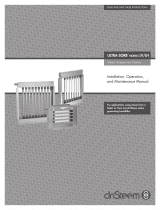
8FBUIFSDPWFS
Optional STS weather cover
The optional weather cover is water-
resistant and designed to protect an STS
unit from rain and sun. The STS weather
cover has been tested and approved by ETL
Testing Laboratories, Inc., and is listed to
UL Standard 1995 and certified to CAN/CSA
Standard C22.2 No. 236.
Figure 13-1:
Weather cover exploded view
Top rear panel
Right side panel
Front Panel
OM-7466
Rear left
side panel
Rear panel
Table 13-1:
Weather cover dimensions
Letter Description
STS 25 to 100 STS 200 to 800
inches mm inches mm
A Height 62 1575 66 1676
B Length 43.5 1105 53 1346
C Width 62 1575 78.25 1988
D Distance from bottom 22 559 22 559
Figure 13-2:
Weather cover dimensions
OM-7465
D
B
C
A
Table 13-2:
Weather cover weights
Weather cover size lbs kg
STS 25 to 100 425 193
STS 200 to 800 550 250
Top front panel
Front left
side panel
Installation
STS_IOM.pdf 13 1/20/2010 10:29:51 AM

1BHFt%3*45&&.454)VNJEJGJFS*OTUBMMBUJPO0QFSBUJPOBOE.BJOUFOBODF.BOVBM
8FBUIFSDPWFS
The weather cover encloses the STS humidifier to protect it from
wind, sun, and rain. The weather cover is fully assembled at the
%3*45&&.GBDUPSZ*UIBTCFFOUFTUFEBOEFWBMVBUFECZ&5-
Testing Laboratories, Inc., and is listed to UL Standard 1995 and
$"/$4"4UBOEBSE$/P
Installation notes
Open panels C and D to make necessary connections to the
humidifier. Refer to the installation section of this manual for all
electrical, supply water, and drain connection requirements.
Installation issues specific to weather cover applications
t *OTUBMMBUJPONVTUDPNQMZXJUIBMMHPWFSOJOHDPEFT
t 5IFCPUUPNPGUIFXFBUIFSDPWFSJTPQFOUPBDDPNNPEBUFQJQJOH
and electrical connections.
t &MFDUSJDBMDPOOFDUJPOTNVTUCFNBEFXJUIBQQSPWFEPVUEPPS
rated, watertight conduit.
t 'SFF[FQSPUFDUJPONVTUCFQSPWJEFEPOBMMXBUFSQJQJOH
t 4UFBNTVQQMZNVTUCFJOTVMBUFE
t "WPJEVTJOHWBQPSIPTFJOPVUEPPSBQQMJDBUJPOTUIFFGGFDUTPG
ultraviolet rays will prematurely age the vapor hose.
t *OTUBMMFSSFRVJSFEUPESJMMBIPMFJOXFBUIFSDPWFSGPSTUFBN
piping. Seal after making steam connection to maintain weather
protection.
t 5IFTUFBNPVUMFUNVTUCFJTPMBUFEXJUIBVOJPOTPUIFTUFBN
supply can be disconnected easily for removal of the weather
cover to gain access to the STS for service and maintenance.
Annual weather cover maintenance requirements
t $IFDLBMMGBTUFOFSTBOEWFSJGZUIFZBSFTFDVSF
t $IFDLGPSBOZTJHOPGMFBLBHFUSBDFCBDLUPPSJHJOBOESFQBJS
Note:
For information about the STS outdoor
enclosure (a weather-tight enclosure with
access doors, supplemental heating and
cooling fan[s]), see the following pages.
Installation
STS_IOM.pdf 14 1/20/2010 10:29:52 AM

%3*45&&.454)VNJEJGJFS*OTUBMMBUJPO0QFSBUJPOBOE.BJOUFOBODF.BOVBMt1BHF
0VUEPPSFODMPTVSF
Notes:
1. The outdoor enclosure has two available steam distribution configurations. The standard configuration has a steam outlet on
the right side of the outdoor enclosure for connecting to steam dispersion unit piping. The optional internal steam distribution
configuration routes steam within the outdoor enclosure and down through the enclosure pipe chase into a building.
2. There are four knockouts located on the right and left side of the enclosure. Knockout sizes are 1½" (hole dia. 50 mm) for STS
models 25-100, and 2" (hole dia. 63.5 mm) for STS models 200-800. Run the electrical power into the enclosure at these knockouts.
3. All piping from the STS unit to the steam outlet is stainless steel pipe. Depending on the application, interconnecting piping from
the steam outlet to the dispersion assembly can be tubing, pipe or DRI-STEEM vapor hose. See Page 36 for more information about
connecting to the dispersion assembly.
4. For STS applications, install a riser trap in the branch line leading to the humidifier.
5. The preferred location for the STS steam control valve is inside the outdoor enclosure. If one of these valves must be located inside
the building, it must be located within 6' (1.8 m) of the humidifier to reduce pressure drop.
6. See the dimensions table on the next page.
DC-1476
Figure 15-1:
STS outdoor enclosure with standard or optional steam outlet, elevation view
Ventilation fans
Power block
Knockouts, 4" (102 mm)
on center
Enclosure drain 1½" pipe
thread (DN40) with male
nipple
Pipe chase
G
A
Standard steam outlet
Optional steam outlet
See Note 2 below
STS humidifier
L
K
6.5" (165 mm)
Installation
STS_IOM.pdf 15 1/20/2010 10:29:52 AM

1BHFt%3*45&&.454)VNJEJGJFS*OTUBMMBUJPO0QFSBUJPOBOE.BJOUFOBODF.BOVBM
0VUEPPSFODMPTVSF
Table 16-1:
STS outdoor enclosure dimensions*
Item Description
STS or STS-DI model number
25-100 200-800
inches mm inches mm
A Enclosure height 56.00 1422 66.00 1676
B Enclosure width 36.00 914 46.00 1168
C
Pipe chase position
4.50 114 4.50 114
D 2.00 57 3.50 89
E
Pipe chase size
20.00 508 32.00 312
F 8.00 203 10.00 254
G
Steam pipe position
6.00 152 8.50 216
H 18.63 473 22.00 559
J 14.50 368 20.50 521
K 12.25 311 11.00 279
L Enclosure length 60.00 1524 78.00 1981
Note:
* See drawings on this and the previous page.
Figure 16-1:
STS outdoor enclosure, top view
DC-1478
B
Standard steam outlet (exits enclosure here)
Intake ventilation fan
D
C
Pipe chase extending 1" (25 mm)
above enclosure floor
STS humidifier
Electrical and cleanout access door
Control panel heater
Control panel
Enclosure drain
E
Optional steam outlet
(exits enclosure through pipe chase)
Valve access door:
t .PEFMTIBWFPOFBDDFTTEPPS
t .PEFMTIBWFUXPBDDFTTEPPST
Intake ventilation fan
Valve section heater
Valve access door
J
H
Installation
F
STS_IOM.pdf 16 1/20/2010 10:29:53 AM

%3*45&&.454)VNJEJGJFS*OTUBMMBUJPO0QFSBUJPOBOE.BJOUFOBODF.BOVBMt1BHF
Table 17-2:
STS outdoor enclosure connection sizes
Description
STS or STS-DI model number
25-100 200-800
Water makeup (fill) wQJQFUISFBE%/ wQJQFUISFBE%/
Drain £w%/ w%/
Condensate return £wQJQFUISFBE%/ £wQJQFUISFBE%/
Steam outlet See STS catalog
Table 17-1:
STS outdoor enclosure weights
STS or STS-DI
model number
Outdoor enclosure
shipping weight*
Outdoor enclosure
operating weight*
lbs kg lbs kg
STS-25 600 272 680 308
STS-50 625 284 840 381
STS-100 640 290 860 390
STS-200 1050 476 1650 748
STS-400 1125 510 1450 794
STS-800 1225 556 2250 1021
Note:
* Includes humidifier
Specifications
t 4FF1BHFGPSDBQBDJUJFTBOEJOQVU
requirements.
t "EEGVMMMPBEBNQT7"$XIFO
using an outdoor enclosure with a heater
package.
t "EEGVMMMPBEBNQT7"$XIFO
using an outdoor enclosure without a
heater package.
0VUEPPSFODMPTVSF
Installation
STS_IOM.pdf 17 1/20/2010 10:29:53 AM

1BHFt%3*45&&.454)VNJEJGJFS*OTUBMMBUJPO0QFSBUJPOBOE.BJOUFOBODF.BOVBM
0VUEPPSFODMPTVSF
Installation
Piping notes:
1. Insulate supply water piping to avoid dripping from condensation. To ensure that water does not remain in the fill line and freeze if there
is a loss of power, DRI-STEEM recommends field installing additional valves upstream of the fill valve in a conditioned space. Power these
valves on the same circuit as the STS; if the power goes off, water drains out of the fill line to prevent freezing (see Figure 18-1). Supply
power for these valves from the same circuit that supplies the STS.
2. Ensure that water lines are protected from freezing conditions.
t *OTUBMMIFBUUSBDJOHBOEJOTVMBUJPOPOGJMMQJQJOHJOTJEFUIFPVUEPPSFODMPTVSF
t *OFYUSFNFPSDSJUJDBMBQQMJDBUJPOTJOXIJDIUIFVOMJLFMZFWFOUPGBXBUFSMFBLDPVMEDBVTFTFWFSFEBNBHF%3*45&&.SFDPNNFOETB
thermostat with a remote sensor on the fill line to cut power to the STS and safety valves to stop fill water to the STS and drain the fill
piping when the temperature is below freezing.
3. DRI-STEEM recommends copper or iron drain piping for outdoor enclosures. On a loss of power the tank water will drain, but not be cooled
by the Drane-kooler because of the field supplied safety shut-off valves. If it is critical to keep the Drane-kooler functional in the case of a
power loss, disconnect the Drane-kooler and relocate it down inside the conditioned space of the building. Pipe the supply water for the
Drane-kooler before the safety shut-off valves.
4. If copper or iron piping is used for both the fill and drain piping, these drains may be tied together. Locate 1" air gap only in spaces with
adequate temperature and air movement to absorb flash steam; otherwise, condensation may form on nearby surfaces. Refer to governing
codes for drain pipe size and maximum discharge water temperature.
Figure 18-1:
Outdoor enclosure installation detail
Open to drain
Vent with check
valve (by installer)
Disconnect (by installer); see Detail A
120 V supply
Open drain
(See Note 4)
Heated building interior
Normally open (fail open) min ½"
electric valve (by installer)
Optional water seal (P-trap) drain
line, min. 1½" (DN40) (See Note 3)
Roof decking
Detail A
120 V
N
To valves (by
installer) (See
Note 1)
To STS humidifier
OM-7558
Drain line, min. 1½" electric valve
(See Note 3)
Domestic water, 80 psig
(582 kPa) maximum
Normally closed
(fail closed) min
3/8" electric valve
(by installer)
Normally closed fill
valve (by factory)
Disconnect
box
120 V from unit
disconnect or other
source (See Note 1)
Make-up water supply piping
(by installer) (See Note 2)
Open drain
(See Note 4)
Humidifier
STS_IOM.pdf 18 1/20/2010 10:29:53 AM

%3*45&&.454)VNJEJGJFS*OTUBMMBUJPO0QFSBUJPOBOE.BJOUFOBODF.BOVBMt1BHF
0VUEPPSFODMPTVSF
Outdoor enclosure mounting
t 5IFPVUEPPSFODMPTVSFNVTUCFMFWFMBOEMPDBUFETPUIBUUIFSFJT
enough clearance for opening the access doors.
t 7FSJGZUIBUUIFQPTJUJPOPGTVQQPSUMFHTQBEPSDVSCQSPQFSMZ
support the unit and that support structure dimensions coincide
with unit dimensions.
t -PDBUFVOJUTPUIBUBJSJOUBLFTBSFOPUUPPDMPTFUPBOZFYIBVTU
fan outlets, gasoline storage, or other contaminants that could
potentially cause dangerous situations. The use and storage
of gasoline or other flammable vapors and liquids in open
containers in the vicinity of this appliance is hazardous.
t 8IFOMPDBUFEPOUIFSPPGUIFPVUEPPSFODMPTVSFBJSJOUBLFTNVTU
be a minimum of 14" (356 mm) above the roof to prevent intake
of snow or splashed rain. Locate the outdoor enclosure so that
prevailing winds do not blow into the air intakes.
t #FTVSFUPSFNPWFBMMTIJQQJOHCSBDLFUTBOEPUIFSQBDLBHJOHQSJPS
to installing the unit.
t %VSJOHUSBOTJUVOMPBEJOHBOETFUUJOHPGUIFVOJUCPMUTBOEOVUT
may have become loosened. Check that all nuts are tightened.
t 5IFSFBSFGPVSLOPDLPVUTMPDBUFEPOUIFSJHIUBOEMFGUTJEFPGUIF
enclosure. It is recommended that the electrical power is run into
the enclosure at these knockouts.
t 5IFPVUEPPSFODMPTVSFJTEFTJHOFEGPSIBOEMJOHCZUXPNFUIPET
In both cases it must be lifted from the bottom base using a
method that holds it level, and keeps it from tipping, falling,
or twisting. If the unit is severely twisted during handling,
permanent damage may occur. It is the installer’s responsibility
to verify the handling equipment’s capability to safely handle the
unit.
t 5IFQSFGFSSFENFUIPEPGMJGUJOHJTCZGPSLMJGU5IJTJTPOMZQPTTJCMF
if forks extend across the entire unit. Forks that do not extend
across the entire unit could cause tipping resulting in unsafe
conditions or damage to the unit.
Figure 19-1:
Outdoor enclosure mounting options
DC-1110
Flush
Legs
14" (356 mm)
OM-1096
14" (356 mm)
OM-1095
Curb
(STS 25-100 only)
Installation
More on the next page ▶
STS_IOM.pdf 19 1/20/2010 10:29:53 AM

1BHFt%3*45&&.454)VNJEJGJFS*OTUBMMBUJPO0QFSBUJPOBOE.BJOUFOBODF.BOVBM
0VUEPPSFODMPTVSF
t 5IFBMUFSOBUJWFNFUIPEPGIBOEMJOHJTUISPVHIUIFVOJUTDIBOOFM
base frame and/or special lifting lug hooks installed on the unit.
All lifting operations must be accomplished with a load spreader
of sufficient width to ensure that the lifting cables clear the side
of the unit. If this type of spreader is not available, wood strips
should be inserted between the cables and unit where necessary.
All four lifting points must be used and will be marked “lift here”
on the unit.
t 5IFPVUEPPSFODMPTVSFIBTUXPBWBJMBCMFTUFBNEJTUSJCVUJPO
configurations. The standard configuration has a steam outlet
on one side of the outdoor enclosure for connecting to steam
dispersion unit piping. The optional internal steam distribution
configuration routes steam within the outdoor enclosure and
down through the pipe chase into a building. See the drawings on
Pages 15 and 16.
Figure 20-1:
Outdoor enclosure clearances
Left side:
36" (914 mm)
Top:
Keep open for access
Back:
12" (305 mm)
Right side:
24" (610 mm)Front:
36" (914 mm)
OM-955
Important note about STS outdoor
enclosure installation
t *OTUBMMBSJTFSUSBQJOUIFCSBODIMJOF
leading to the humidifier.
t 5IFQSFGFSSFEMPDBUJPOGPSUIF454TUFBN
control valve is inside the outdoor
enclosure. If one of these valves must be
located inside the building, it must be
located within 6' (1.8 m) of the humidifier
to reduce pressure drop.
Installation
More on the next page ▶
STS_IOM.pdf 20 1/20/2010 10:29:53 AM
/