Page is loading ...

iSonic 4000
Open-Channel Flow Meter
HYB-UM-02509-EN-04 (November 2018)
User Manual

iSonic 4000, Open-Channel Flow Meter
Page ii November 2018HYB-UM-02509-EN-04

CONTENTS
Scope of This Manual . . . . . . . . . . . . . . . . . . . . . . . . . . . . . . . . . . . . . . . . . . . . . . . . . . . . . . . . . . . . . . . . . . . 5
Safety Precautions and Instructions. . . . . . . . . . . . . . . . . . . . . . . . . . . . . . . . . . . . . . . . . . . . . . . . . . . . . . . . . . 5
Installation. . . . . . . . . . . . . . . . . . . . . . . . . . . . . . . . . . . . . . . . . . . . . . . . . . . . . . . . . . . . . . . . . . . . . . . 5
Power Connection . . . . . . . . . . . . . . . . . . . . . . . . . . . . . . . . . . . . . . . . . . . . . . . . . . . . . . . . . . . . . . . . . . 5
Protection Class . . . . . . . . . . . . . . . . . . . . . . . . . . . . . . . . . . . . . . . . . . . . . . . . . . . . . . . . . . . . . . . . . . . 5
Setup and Operation . . . . . . . . . . . . . . . . . . . . . . . . . . . . . . . . . . . . . . . . . . . . . . . . . . . . . . . . . . . . . . . . 5
Cleaning . . . . . . . . . . . . . . . . . . . . . . . . . . . . . . . . . . . . . . . . . . . . . . . . . . . . . . . . . . . . . . . . . . . . . . . . 5
Repairing Faults . . . . . . . . . . . . . . . . . . . . . . . . . . . . . . . . . . . . . . . . . . . . . . . . . . . . . . . . . . . . . . . . . . . 5
RoHs. . . . . . . . . . . . . . . . . . . . . . . . . . . . . . . . . . . . . . . . . . . . . . . . . . . . . . . . . . . . . . . . . . . . . . . . . . . 6
Battery Disposal . . . . . . . . . . . . . . . . . . . . . . . . . . . . . . . . . . . . . . . . . . . . . . . . . . . . . . . . . . . . . . . . . . . 6
System Description . . . . . . . . . . . . . . . . . . . . . . . . . . . . . . . . . . . . . . . . . . . . . . . . . . . . . . . . . . . . . . . . . . . . 6
Nameplate. . . . . . . . . . . . . . . . . . . . . . . . . . . . . . . . . . . . . . . . . . . . . . . . . . . . . . . . . . . . . . . . . . . . . . . 6
System Settings. . . . . . . . . . . . . . . . . . . . . . . . . . . . . . . . . . . . . . . . . . . . . . . . . . . . . . . . . . . . . . . . . . . . 7
Installation. . . . . . . . . . . . . . . . . . . . . . . . . . . . . . . . . . . . . . . . . . . . . . . . . . . . . . . . . . . . . . . . . . . . . . . . . . 8
Installation the EchoPod DL-10 Sensor . . . . . . . . . . . . . . . . . . . . . . . . . . . . . . . . . . . . . . . . . . . . . . . . . . . . . 8
Mounting Positions . . . . . . . . . . . . . . . . . . . . . . . . . . . . . . . . . . . . . . . . . . . . . . . . . . . . . . . . . . . . . . . . . 9
Power Connections . . . . . . . . . . . . . . . . . . . . . . . . . . . . . . . . . . . . . . . . . . . . . . . . . . . . . . . . . . . . . . . . . . . . 9
Auxiliary Power . . . . . . . . . . . . . . . . . . . . . . . . . . . . . . . . . . . . . . . . . . . . . . . . . . . . . . . . . . . . . . . . . . . 10
Operation . . . . . . . . . . . . . . . . . . . . . . . . . . . . . . . . . . . . . . . . . . . . . . . . . . . . . . . . . . . . . . . . . . . . . . . . . 12
Function Buttons. . . . . . . . . . . . . . . . . . . . . . . . . . . . . . . . . . . . . . . . . . . . . . . . . . . . . . . . . . . . . . . . . . 12
Display Icons . . . . . . . . . . . . . . . . . . . . . . . . . . . . . . . . . . . . . . . . . . . . . . . . . . . . . . . . . . . . . . . . . . . . 12
Initial Screens . . . . . . . . . . . . . . . . . . . . . . . . . . . . . . . . . . . . . . . . . . . . . . . . . . . . . . . . . . . . . . . . . . . . 12
Setting a PIN. . . . . . . . . . . . . . . . . . . . . . . . . . . . . . . . . . . . . . . . . . . . . . . . . . . . . . . . . . . . . . . . . . . . . 13
Logging In . . . . . . . . . . . . . . . . . . . . . . . . . . . . . . . . . . . . . . . . . . . . . . . . . . . . . . . . . . . . . . . . . . . . . . 13
Logging Out. . . . . . . . . . . . . . . . . . . . . . . . . . . . . . . . . . . . . . . . . . . . . . . . . . . . . . . . . . . . . . . . . . . . . 13
Programming. . . . . . . . . . . . . . . . . . . . . . . . . . . . . . . . . . . . . . . . . . . . . . . . . . . . . . . . . . . . . . . . . . . . . . . 14
Main Menu. . . . . . . . . . . . . . . . . . . . . . . . . . . . . . . . . . . . . . . . . . . . . . . . . . . . . . . . . . . . . . . . . . . . . . 14
Meter Setup Menu. . . . . . . . . . . . . . . . . . . . . . . . . . . . . . . . . . . . . . . . . . . . . . . . . . . . . . . . . . . . . . . . . 15
Measurement Menu. . . . . . . . . . . . . . . . . . . . . . . . . . . . . . . . . . . . . . . . . . . . . . . . . . . . . . . . . . . . . . . . 16
Input/Outputs Menu . . . . . . . . . . . . . . . . . . . . . . . . . . . . . . . . . . . . . . . . . . . . . . . . . . . . . . . . . . . . . . . 20
Clear Total . . . . . . . . . . . . . . . . . . . . . . . . . . . . . . . . . . . . . . . . . . . . . . . . . . . . . . . . . . . . . . . . . . . . . . 23
Communications Menu. . . . . . . . . . . . . . . . . . . . . . . . . . . . . . . . . . . . . . . . . . . . . . . . . . . . . . . . . . . . . . 24
Miscellaneous. . . . . . . . . . . . . . . . . . . . . . . . . . . . . . . . . . . . . . . . . . . . . . . . . . . . . . . . . . . . . . . . . . . . 24
Info Menu . . . . . . . . . . . . . . . . . . . . . . . . . . . . . . . . . . . . . . . . . . . . . . . . . . . . . . . . . . . . . . . . . . . . . . 25
User Manual
Page iii November 2018 HYB-UM-02509-EN-04

PIN Menu. . . . . . . . . . . . . . . . . . . . . . . . . . . . . . . . . . . . . . . . . . . . . . . . . . . . . . . . . . . . . . . . . . . . . . . 25
Login Menu . . . . . . . . . . . . . . . . . . . . . . . . . . . . . . . . . . . . . . . . . . . . . . . . . . . . . . . . . . . . . . . . . . . . . 25
Troubleshooting . . . . . . . . . . . . . . . . . . . . . . . . . . . . . . . . . . . . . . . . . . . . . . . . . . . . . . . . . . . . . . . . . . . . . 26
Control LED . . . . . . . . . . . . . . . . . . . . . . . . . . . . . . . . . . . . . . . . . . . . . . . . . . . . . . . . . . . . . . . . . . . . . 26
Replace Meter’s Electronics . . . . . . . . . . . . . . . . . . . . . . . . . . . . . . . . . . . . . . . . . . . . . . . . . . . . . . . . . . . 26
Specications. . . . . . . . . . . . . . . . . . . . . . . . . . . . . . . . . . . . . . . . . . . . . . . . . . . . . . . . . . . . . . . . . . . . . . . 27
Dimensions . . . . . . . . . . . . . . . . . . . . . . . . . . . . . . . . . . . . . . . . . . . . . . . . . . . . . . . . . . . . . . . . . . . . . . . . 28
Main Menu Program Structure . . . . . . . . . . . . . . . . . . . . . . . . . . . . . . . . . . . . . . . . . . . . . . . . . . . . . . . . . . . . 29
Meter Setup . . . . . . . . . . . . . . . . . . . . . . . . . . . . . . . . . . . . . . . . . . . . . . . . . . . . . . . . . . . . . . . . . . . . . 29
Measurements . . . . . . . . . . . . . . . . . . . . . . . . . . . . . . . . . . . . . . . . . . . . . . . . . . . . . . . . . . . . . . . . . . . 29
Inputs/Outputs . . . . . . . . . . . . . . . . . . . . . . . . . . . . . . . . . . . . . . . . . . . . . . . . . . . . . . . . . . . . . . . . . . . 30
Total . . . . . . . . . . . . . . . . . . . . . . . . . . . . . . . . . . . . . . . . . . . . . . . . . . . . . . . . . . . . . . . . . . . . . . . . . . 30
Communications. . . . . . . . . . . . . . . . . . . . . . . . . . . . . . . . . . . . . . . . . . . . . . . . . . . . . . . . . . . . . . . . . . 30
Miscellaneous. . . . . . . . . . . . . . . . . . . . . . . . . . . . . . . . . . . . . . . . . . . . . . . . . . . . . . . . . . . . . . . . . . . . 30
Info . . . . . . . . . . . . . . . . . . . . . . . . . . . . . . . . . . . . . . . . . . . . . . . . . . . . . . . . . . . . . . . . . . . . . . . . . . 30
Pin . . . . . . . . . . . . . . . . . . . . . . . . . . . . . . . . . . . . . . . . . . . . . . . . . . . . . . . . . . . . . . . . . . . . . . . . . . . 30
Login . . . . . . . . . . . . . . . . . . . . . . . . . . . . . . . . . . . . . . . . . . . . . . . . . . . . . . . . . . . . . . . . . . . . . . . . . 30
Flow Meter ModBus® Register Table. . . . . . . . . . . . . . . . . . . . . . . . . . . . . . . . . . . . . . . . . . . . . . . . . . . . . . . . . 31
iSonic 4000 Flow Meter Conversion Table . . . . . . . . . . . . . . . . . . . . . . . . . . . . . . . . . . . . . . . . . . . . . . . . . . 35
Rights . . . . . . . . . . . . . . . . . . . . . . . . . . . . . . . . . . . . . . . . . . . . . . . . . . . . . . . . . . . . . . . . . . . . . . . . . 35
Wiring the iSonic 4000 Meter to an ORION® Cellular LTE Endpoint . . . . . . . . . . . . . . . . . . . . . . . . . . . . . . . . . . . . . 36
iSonic 4000, Open-Channel Flow Meter
Page iv November 2018HYB-UM-02509-EN-04

SCOPE OF THIS MANUAL
This manual contains instructions for installing, operating and programming the iSonic 4000 flow meter.
MPORTANTI
Read this manual carefully before attempting any installation or operation. Keep the manual accessible for future reference.
SAFETY PRECAUTIONS AND INSTRUCTIONS
Some procedures in this manual require special safety considerations. In such cases, the text is emphasized with the
following symbols:
Symbol Explanation
Warning indicates the potential for severe personal injury, death or substantial property damage.
Comply with the instructions and proceed with care.
Caution indicates the potential for minor personal injury or property damage. Comply with the
instructions and proceed with care.
Before installing or using this product, please read this instruction manual thoroughly. Only qualified personnel should install
and/or repair this product. If a fault appears, contact your distributor.
Installation
• Do not place any unit on an unstable surface that may allow it to fall.
• Never place the units above a radiator or heating unit.
• Route all cabling away from potential hazards.
• Isolate from the mains before removing any covers.
Power Connection
• Use only the type of power source suitable for electronic equipment. If in doubt, contact your distributor. Ensure that any
power cables are of a sufficiently high current rating.
• All units must be earthed to eliminate risk of electric shock. Failure to properly earth a unit may cause damage to that unit
or data stored within it.
Protection Class
The device has protection class IP 67 and needs to be protected against dripping water, water, oils, etc.
Setup and Operation
Adjust only those controls that are covered by the operating instructions. Improper adjustment of other controls may result in
damage, incorrect operation or loss of data.
Cleaning
Switch off all units and isolate from mains before cleaning. Clean using a damp cloth. Do not use liquid or aerosol cleaners.
Repairing Faults
Disconnect all units from power supply and have it repaired by a qualified service person if any of the following occurs:
• If any power cord or plug is damaged or frayed
• If a unit does not operate normally when operating instructions are followed
• If a unit exposed to rain/water or if any liquid has been spilled into it
• If a unit has been dropped or damaged
• If a unit shows a change in performance, indicating a need for service.
Scope of This Manual
Page 5 November 2018 HYB-UM-02509-EN-04

WARNING
FAILURE TO ADHERE TO THESE SAFETY INSTRUCTIONS MAY RESULT IN DAMAGE TO THE PRODUCT OR SERIOUS BODILY
INJURY.
RoHs
Our products are RoHs compliant.
Battery Disposal
The batteries contained in our products need to be disposed of as per your local legislation, according to EU directive
2006/66/EG.
SYSTEM DESCRIPTION
The iSonic 4000 Ultrasonic flow meter is designated for flow measurements in open channels and partially filled pipes and
volume measurements of liquids in tanks. You can connect one ultrasonic level sensor with 4…20 mA output to the unit.
Flows are consequently calculated from measured levels using pre-programmed formulas for various primary flow elements
(flumes, weirs) or from the Q/h table. The unit can also calculate flow rates in partially filled pipes and angular open channels
using the Manning equation.
• The iSonic 4000 flow meter is an IP67 device in a robust wall-mounted metal case, with a large graphic display.
• The flow meter menu is operated with three front panel high endurance buttons.
• The flow meter is powered externally by 92…275V AC / 50…60 Hz. The DC version is powered externally by 9…36V DC
(maximum 9 W).
• You can operate the flow meter via connection to a USB or Ethernet interface with Flow Meter Tool software, which can be
used for parameter setup and datalogger download.
• The flow meter has an internal datalogger with 2 MB capacity for approximately 130,000 logged lines. You can download
the logged data with the Flow Meter Tool software and save it in .csv format to a PC.
• USB, Ethernet, ADE, RS232, Modbus RS485/RS422 galvanic isolated interfaces are mounted on the board.
• The flow meter has one analog output (0…20 mA or 4…20 mA) and two galvanic isolated pulse outputs.
Nameplate
Look at the device nameplate to make sure the device is delivered according to your order. Check for the correct supply
voltage printed on the nameplate.
System Description
Page 6 November 2018HYB-UM-02509-EN-04

System Settings
Flow Meter Tool Settings Settings Control Panel
Driver Details
System Description
Page 7 November 2018 HYB-UM-02509-EN-04

INSTALLATION
WARNING
INSTALLATION INSTRUCTIONS GIVEN IN THE FOLLOWING ARE TO BE OBSERVED IN ORDER TO PROVIDE
FUNCTIONALITY AND SAFE OPERATION OF THE METER.
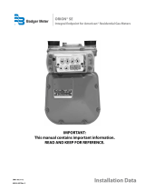
Installation the EchoPod DL-10 Sensor
Sensor EchoPod
Viton Gasket
1. Insert the gasket onto the threaded end of the sensor.
2. Screw the sensor into the stainless steel mounting bracket.
OTE:N Install the sensor at a maximum of 49.21 in. (125 cm) above the flume bottom (minimal measured level) with a
minimum of 1.97 in. (5 cm) distance above the maximal measured level.
Max
125 cm
3. Connect the sensor to the 4…20 mA input terminal on the bottom side of display board.
Installation
Page 8 November 2018HYB-UM-02509-EN-04

Mounting Positions
Manhole Flume
Size Max. Flow Max. Water Level V-Mt H-Mt
in. (DN) g/sec (l/sec) in. (mm) in. (mm) in. (mm)
4 (100) 1.32 (5) 5.83 (148) 23.62 (600) 5.75 (146)
6 (150) 4.23 (16) 8.94 (227) 23.62 (600) 7.75 (197)
8 (200) 9.25 (35) 12.28 (312) 23.62 (600) 9.76 (248)
10 (250) 16.64 (63) 15.55 (395) 27.56 (700) 11.73 (298)
12 (300) 24.83 (94) 18.00 (457) 27.56 (700) 13.74 (349)
Parshall Flume
Size Max. Flow V-Mt H-Mt
Sensor
MT
V
H
in. (DN) g/sec (l/sec) in. (mm) in. (mm)
3 (75) 14.26 (54) 30.71 (780) 12.00 (305)
6 (150) 30.12 (114) 30.71 (780) 15.98 (406)
9 (230) 77.67 (284) 38.19 (970) 22.52 (572)
12 (305) 157.98 (598) contact factory contact factory
18 (455) 24.83 (94) contact factory contact factory
POWER CONNECTIONS
FOR THE 2 × M20 CABLE INLETS, USE ONLY FLEXIBLE ELECTRIC CABLES. USE SEPARATE CABLE INLETS FOR AUXILIARY
POWER, SIGNAL AND INPUT/OUTPUT CABLES.
6.46 in.
(164 mm)
5.83 in.
(148 mm)
9.80 in.
(249 mm)
3.15 in.
(60 mm)
M20 (×2)
Ø 0.20 in.
(5.2 mm)
2.56 in.
(65 mm)
3.15 in.
(60 mm)
Power Connections
Page 9 November 2018 HYB-UM-02509-EN-04

Auxiliary Power
WARNING
• DO NOT CONNECT METER TO POWER SOURCE UNDER CONDITIONS THAT COULD CAUSE PERSONAL INJURY OR
DAMAGE TO THE EQUIPMENT.
• WIRING OF THIS EQUIPMENT MUST COMPLY WITH LOCAL AND NATIONAL CODES AND BE WITHIN THE VOLTAGE
AND FREQUENCY RATING LISTED ON THE METER.
• INSTALL EQUIPMENT WITH AN EXTERNAL MEANS FOR DISCONNECTING IT FROM POWER, SUCH AS A SWITCH OR A
CIRCUIT BREAKER.
1. Slightly loosen the lower cover screws.
2. Completely loosen both upper cover screws.
3. Open the cover to the lower side.
4. Push the auxiliary power cable through the upper cable inlet.
5. Connect the power as shown in Figure 1 or Figure 2, depending on the version (AC or DC) of meter you have.
6. Close the cover and tighten the four screws.
Figure 1: Power supply 92…275V AC (50/60 Hz);
recommended cable size min. 0.3 sq. in. (0.75 mm²)
Figure 2: Power supply 9…36V DC (max. 9 W);
recommended cable size min. 0.3 sq. in. (0.75 mm²)
Power Connections
Page 10 November 2018HYB-UM-02509-EN-04

Conguring Input/Outputs (I/O)
RS-Interface
Digital
Output/Input
Analog Output
Solid-State
Relay
Auxiliary Power
USB
Sensor Input
Display
Ethernet
RS-Interface
DIP switch
Input/Output Description Terminal
Analog output* 0…20 mA, 4…0 mA, RL < 800 Ohm, 0…10 mA 7 (+), 8 (-), 9 (GND)
Digital output 1* Open collector max. 10 kHz, Passive max. 32V DC, <100 Hz 100 mA, >100 Hz 20 mA,
Active 24V DC, 20 mA, (can be powered by analog output if not used)
3 (-),4 (+)
2* Open collector max. 10 kHz, Passive max. 32V DC, <100 Hz 100 mA, >100 Hz 20 mA,
Active 24V DC, 20 mA, (can be powered by analog output if not used)
1 (-)
2 (+)
3 Solid-state relays max. 230V AC, 500 mA, max. 1 Hz (function is linked to Output 2) S1 and S2
Digital input* 5…30V DC 5 (-) and 6 (+)
RS interfaces* RS232, RS485 and RS422 with Modbus RTU.
Mode can be configured by DIP switches also termination ON or OFF. For the
RS485, connect the A wire to the Y terminal and the B wire to the Z terminal.
422 232 485
A RxD
B
Z TxD B
Y A
G (GND)
USB USB Device CDC (Host Mass Storage) Micro USB
Ethernet* Ethernet Interface connection RJ45 socket
* All marked inputs and outputs are according to safety data TNV-1 IEC 60950-1.
Input and Output Cable Connections
For the normal I/Os, use shielded cables. Connect the shield of the cable to one of the grounding screws. Recommended
cable is LiYCY size min. 0.06 sq. in. (0.14 mm²).
Solid-State Output
If using a second cable gland for the normal I/Os, use one cable and cable gland for the power supply and solid-state relay.
Recommended cable size is min. 0.3 sq. in. (0.75 mm²).
• USE SEPARATE CABLE INLETS FOR CABLES CONNECTED TO THE SOLID-STATE RELAY OUTPUT AND CABLES
CONNECTED TO THE OTHER INPUT/OUTPUTS.
• WITH MULTIPHASE POWER, SOLID-STATE RELAY SHOULD HANDLE ONLY THE SAME PHASE THAT IS USED FOR
POWERING THE METER.
Power Connections
Page 11 November 2018 HYB-UM-02509-EN-04

OPERATION
Function Buttons
All programming is accomplished using the three function buttons on the front of the unit. Screen
navigation and digit and parameter selection is performed by a combination of these buttons.
Use the up-arrow to scroll through the menu screens or to advance numerical digits to change values.
Use the right-arrow to select digits from left to right and allows or to enter a submenu.
Use EXIT SAVE to save changed values, return to a previous menu or toggle between Measuring mode and Programing mode.
Display Icons
Minor battery power (Realtime clock) W Sensor warming
Device error 0 Sensor not connected
No keyword active M Sensor measuring
USB active S Simulation active
MeterSetup
MainMenu
Menu Header
Scroll Bar
Indicates a Submenu
Submenu
Initial Screens
From the Main Menu, press EXIT SAVE to display the current values and system information. The rst screen to display
depends on the application type (open channel or tank).
First screen for
open channel applications:
First screen for tank applications: Second screen for both applications.
Volume 305.6 m
3
Level 0.50 m
Flow 8.85 m
3
/s
M
Parameter Value
Unit of
Measure
Icons
Volume 50.3 m
3
Level 0.503 m
1
Parameter Value
Unit of
Measure
Icons
Tag: iSonic 4000
1.2.00
2017-07-30 10:05
Current 10.184 mA
Tag
Application
Version
Date & Time
Parameter,
Value & Unit
Operation
Page 12 November 2018HYB-UM-02509-EN-04

Setting a PIN
The iSonic 4000 flow meter security feature allows the option to restrict access to the meter by way of a 6-digit Personal
Identification Number (PIN). The system administrator can set up a single PIN for each of the three different levels of access:
• Administration – allows access to all iSonic 4000 flow meter menu configuration screens.
• Service – allows access to service-level and user-level menu configuration screens.
• User – allows access only to user-level menu configuration screens.
OTE:N For a lost PIN, Contact Badger Meter Technical Support at 800-456-5023 for a replacement PIN.
Not all levels of access need to be set. If no PINs are set up, any user will have access to all functions.
1. From the Main Menu, press the right-arrow.
2. From the Meter Setup menu, press the up-arrow until the Pin menu is displayed.
3. Press the right-arrow to display the PINS Control menu.
4. Press the right-arrow to highlight ON or OFF.
5. With either ON or OFF highlighted, press the up-arrow to display ON.
6. Press EXIT SAVE to save the ON setting.
7. With the Control menu highlighted, press the up-arrow to display the required security level (user, service, or admin).
8. With the required security level highlighted, press EXIT SAVE to display the rst of six zeros (digits).
9. Press the up-arrow to change the rst digit, followed by pressing the right-arrow to select the next digit.
10. Press the EXIT SAVE button to save the PIN number for that security level.
Logging In
To change any parameter, the PIN entered must provide the proper security privilege required by the parameter.
To enter a PIN, go to the Login menu and enter the PIN for the required security level.
Once you are properly logged in, the unlocked icon appears on the meter display.
OTE:N A PIN Error message displays if the incorrect PIN is entered.
Logging Out
To log out, follow steps 1 through 8 under "Setting a PIN". At step 9, enter an invalid PIN, then press EXIT SAVE.
Operation
Page 13 November 2018 HYB-UM-02509-EN-04

PROGRAMMING
Main Menu
From the Main Menu, you can access these submenus, each of which is described on the following pages:
• Meter Setup
• Measurements
• Input and Outputs
• Totalizer Reset
• Communication
• Miscellaneous
• Information
• Pin
The security levels are:
A
Administrative
S
Service
U
User
Parameters indicated by the battery icon, if changed, will affect battery performance.
To program the security levels, see "Setting a PIN" on page 13. No passwords were set at the factory.
Programming
Page 14 November 2018HYB-UM-02509-EN-04

Meter Setup Menu
Application Tank
A
Select for a tank application.
Open Channel
A
Select for an open channel application.
Sensor Interval
S
Setup of time measurement interval(s); default value is 1 second; larger
interval (for instance, 300 seconds) is set when unit is powered from
battery
WarmUpTime
S
Powering time of sensor(s) before measurement; larger interval is set
when unit is powered from battery
LowerRangeValue
A
The minimum level value of used sensor = 4 mA in selected level units
UpperRangeValue
A
The maximum level value of used sensor = 20 mA in selected level units
Offset
S
Level offset in selected level units, depends of sensor mounting position
Programming
Page 15 November 2018 HYB-UM-02509-EN-04

Measurement Menu
Length
U
Establishes the unit of measure for the length
Display Length Unit
ft Feet
m Meter
in. Inch
cm Centimeter
mm Millimeter
DecimalPlaces – set of the decimal places of the Length values
Flow Rate
U
Establishes the unit of measure for the flow rate
Display Flow Unit Display Flow Unit
L/s Liters/Second gal/s Gallons/Sec.
L/min Liters/Minute gal/min Gallons/Min.
L/h Liters/Hour gal/h Gallons/Hour
m
3
/s Cubic Meters/Sec. MG/d MillionGallons/Day
m
3
/min Cubic Meters/Min. IG/s ImperialGallons/Sec.
m
3
/h Cubic Meters/Hour IG/min ImperialGallons/Min.
ft
3
/s Cubic Feet/Sec. IG/h ImperialGallons/Hour
ft
3
/min Cubic Feet/Min. Bbl/min Barrel/Min
ft
3
/h Cubic Feet/Hour.
DecimalPlaces – set of the decimal places of the Flow Rate values
Volume
U
Display Volume Unit Display Volume Unit
L Liters MG MegaGallons
hL HectoLiter IG Imperial Gallons
m
3
Cubic Meters bbl Barrel
Ft
3
Cubic Feet Aft Acre Feet
gal US Gallons
DecimalPlaces – set of the decimal places of the Volume values
Programming
Page 16 November 2018HYB-UM-02509-EN-04

Equation Selection
A
Q/h Table selection is possible only from the Flow Meter Tool software
Display Description
Exponential Eq Exponential Function Q = K h
exp
Contract.Weir Contracted Weir
Suppress.Weir Suppressed Weir
CipolettiWeir Cipoletti Weir
VNotchWeir30° V Notch Weir 30°
VNotchWeir45° V Notch Weir 45°
VNotchWeir60° V Notch Weir 60°
VNotchWeir90° V NotchWeir 90°
ManningRect. Manning Rectangle Flume
ManningPipe Manning Pipe
Pars.Flume1" Parschall Flume 1"
Pars.Flume2" Parschall Flume 2"
Pars.Flume3" Parschall Flume 3"
Pars.Flume6" Parschall Flume 6"
Pars.Flume9" Parschall Flume 9"
Par.Flume12" Parschall Flume 12"
Par.Flume18" Parschall Flume 18"
Par.Flume24" Parschall Flume 24"
Par.Flume36" Parschall Flume 36"
Par.Flume48" Parschall Flume 48"
Par.Flume60" Parschall Flume 60"
Manh.Flume4" Manhole Flume 4"
Manh.Flume6" Manhole Flume 6"
Manh.Flume8" Manhole Flume 8"
Manh.Flume10" Manhole Flume 10"
Manh.Flume12" Manhole Flume 12"
Equation Params
A
Exponent value in for equation (Q= K h exp) Exponent
Coefficient value in for equation (Q= K h exp) Coefficient
Measured profile width (Weirs, Manning equation) Width
Rectangular profile slopes angle (Manning equation) Angle
Measured pipe Radius (Manning equation) Radius
Water Surface Slope (Manning equation) WaterSurfaceSlope
Surface Roughness coefficient (Manning equation) SurfaceRoughness
Maximum Water Level MaximumWaterLevel
Flow Rate Upper Range Value UpperRangeValue
Maximum Water Level /SetDefaultVal.
Set of the Maximum Water Level for the selected primary element – the value is possible to
edit further.
Upper Range Value /Calculate
Is calculating the maximal Flow Rate value for Maximal Water Level - the value is possible to edit
further – this parameter is used also for outputs (Upper Range Value=100% - full range)
Programming
Page 17 November 2018 HYB-UM-02509-EN-04

Open Channel Calculation
Volumetric flow is calculated from actual water level. Actual water level is limited by the maximum water level.
The Exponential Equation for general Parshall or Manhole flume: Q=K.Q
exp
Q – Volumetric flow [m³/s]
K – Coefficient [m
(3-n)
/s]
h – Water level [m]
exp – Exponent [-]
Predefined Flume Equation [m³/s, m] Max. Water Level [m]
Parshall flume 1 in. Q = 0.0604 • h
1.55
0.230
Parshall flume 2 in. Q = 0.1207 • h
1.55
0.260
Parshall flume 3 in. Q = 0.1771 • h
1.55
0.667
Parshall flume 6 in. Q = 0.3810 • h
1.55
0.724
Parshall flume 9 in. Q = 0.5350 • h
1.55
0.876
Parshall flume 12 in. Q = 0.7050 • h
1.55
0.925
Parshall flume 18 in. Q = 1.0670 • h
1.55
0.925
Parshall flume 24 in. Q = 1.4290 • h
1.55
0.925
Parshall flume 36 in. Q = 2.1900 • h
1.57
0.925
Parshall flume 48 in. Q = 2.9600 • h
1.58
0.925
Parshall flume 60 in. Q = 3.7500 • h
1.59
0.925
Manhole flume 4 in. Q = 0.2343 • h
1.95
0.149
Manhole flume 6 in. Q = 0.3026 • h
1.95
0.227
Manhole flume 8 in. Q = 0.3424 • h
1.95
0.313
Manhole flume 10 in. Q = 0.3868 • h
1.95
0.396
Manhole flume 12 in. Q = 0.4345 • h
1.95
0.457
Contracted rectangular weir
Equation Q = 1.84 • (L - 0.2 • h) • h
1.5
Q – Volumetric flow [m³/s]
1.84 – Coefficient [√m/s]
L – Width [m]
h – Water level [m]
Suppressed rectangular weir
Equation Q = 1.84 • L • h
1.5
Q – Volumetric flow [m³/s]
1.84 – Coefficient [√m/s]
L – Width [m]
h – Water level [m]
Cipoletti rectangular weir
Equation Q = 1.84 • L • h
1.5
Q – Volumetric flow [m³/s]
1.84 – Coefficient [√m/s]
L – Width [m]
h – Water level [m]
V-notch weir 30°
Equation Q=
8
√ • tan
(
30
2
)
• 0.586 • (h + 0.0021)
2.5
2 • g
12
2
Q – Volumetric flow [m³/s]
g – Standard gravity 9.80665 [m/s
2
]
h – Water level [m]
Programming
Page 18 November 2018HYB-UM-02509-EN-04

V-notch weir 45°
Equation Q=
8
√ • tan
(
45
2
)
• 0.580 • (h + 0.0015)
2.5
2 • g
12
2
Q – Volumetric flow [m³/s]
g – Standard gavity 9.80665 [m/s
2
]
h – Water level [m]
V-notch weir 60°
Equation Q=
8
√ • tan
(
60
2
)
• 0.577 • (h + 0.0012)
2.5
2 • g
12
2
Q – Volumetric flow [m³/s]
g – Standard gavity 9.80665 [m/s
2
]
h – Water level [m]
V-notch weir 90°
Equation Q=
8
√ • tan
(
90
2
)
• 0.578 • (h + 0.0008)
2.5
2 • g
12
2
Q – Volumetric flow [m³/s]
g – Standard gavity 9.80665 [m/s
2
]
h – Water level [m]
Manning equation: Q = 1/n R
h
2/3
I
1/2
A R
h
=A/P
Manning rectangular
(
h • L+
h
2
)
2/3
( )
Equation Q =
1
tga
• √
I
• h • L +
h
2
n
2 • h
+L
tga
sina
Q – Volumetric flow [m³/s]
n – Gauckler-Manning coefficient [s/
3
√m]
L – Width [m]
h – Water level [m]
a – Angle [°]
I – Water surface slope [m/m]
Manning pipe
(
(a - sina) • r
)
2/3
• √ I •
(
(a - sina) • r
2
)
where
Equation Q =
1
n
2 a 2
a =
2 • π - 2 • arcsin
(
2 • h • r - h
2
)
| h > r
√
r
2 • arcsin
(
2 • h • r - h
2
)
| h ≤ r
√
r
Q – Volumetric flow [m³/s]
n – Gauckler-Manning coefficient [s/
3
√m]
L – Width [m]
h – Water level [m]
I – Water surface slope [m/m]
Material n = s/
3
√m Material n = s/
3
√m Material n = s/
3
√m
Glass , PVC 0.010 Gravel, firm 0.023 Natural channels, poor 0.060
Cement, concrete, steel 0.011 Earth channel, gravelly 0.025 Floodplains, heavy brush 0.075
Brick 0.015 Earth channel, weedy 0.030 Floodplains, trees 0.150
Earth, smooth 0.018 Natural streams, clean 0.035
Earth channel, clean 0.022 Floodplains, light brush 0.050
Programming
Page 19 November 2018 HYB-UM-02509-EN-04

Input/Outputs Menu
Analog Output Range
S
Establishes the range of the analog output signal: 0…100% (= full scale). The
following current output ranges are available:
• 0…20 mA
• 4…20 mA
• 0…10 mA
Analog output active
Analog output passive
OTE:N If an error message displays, set the current according the
programing of the Alarm Mode below. When you select bidirectional
operation, you can signal the flow direction via digital outputs.
Alarm Mode
S
This parameter configures the behavior of the analog output during alarm
conditions. The options are OFF, 3.5 mA and 23 mA.
• OFF: Analog signal is based on flow rate and always within the
configured range.
• 3.5 mA: During alarm conditions, the analog signal is 3.5.
• 23 mA: During alarm conditions, the analog signal is 23 mA.
For example, if the analog range is 4…20 mA and the alarm mode is set
to 23 mA, then during a full scale flow alarm condition, the analog output
current will be 23 mA.
Compensation
S
Correction of the current value output.
Digital Input
S
Digital input lets you reset totalizers (remote reset), interrupt flow measurement (PosZeroReturn) or
ADE. Input switching is provided by applying an external potential of 5…30V DC
or by an internal voltage source of 24V DC (analog output if not used).
Programming
Page 20 November 2018HYB-UM-02509-EN-04
/