Page is loading ...

HR-RED
High Resolution Remote Electronic Display
DSY-UM-02471-EN-01 (November 2017)
Installation Data
SCOPE OF MANUAL
This manual provides instructions for installing and using
the HR-RED (High Resolution Remote Electronic Display) .
Product Description
The HR-RED is an electronic display designed to provide remote
visual readings when connected directly to Badger Meter®
Recordall® Disc, Turbo, Compound, and Fire Series meters
equipped with high resolution (HR) encoders—HR-E®, HR-E LCD,
HR-E LCD 4-20—or E-Series® Ultrasonic meters that are not easily
accessible or are in difficult to read locations. Installations such
as those inside houses or buildings, meter vaults, or dangerous
industrial locations are ideal for the HR-RED.
For additional information and product specifications, refer to the
HR-RED product data sheet, available in the Resource Library
at www.badgermeter.com.
STANDARD COMPONENTS
HR-RED Kit 64466-002
• Strain relief ring
• Three (3) connectors for wires
• Torx® seal screw
• Unit of measure adhesive label
Installation Tools
The following customer-supplied tools are recommended for installing the HR-RED. Items with a part number are available
from Badger Meter.
• Electric drill
• 3/16 in. carbide tip masonry drill bits
• Screw driver
• 59983-001 Crimping tool
• 59989-001 Cable stripper
• 59991-001 Wire cutting pliers
Wire Options (if cable supplied with the meter/encoder is not sucient)
• 64153-003 One (1) ft Belden® cable
• 68307-001 Nine (9) in. Twist Tight® connector cable
• 66488-007 Ten (10) in. Nicor® connector cable

Location
Page 2 November 2017DSY-UM-02471-EN-01
LOCATION
The HR-RED can be installed indoors or outdoors.
MPORTANTI
While the HR-RED electronics and battery are environmentally sealed and suitable for outdoor installation, the wire
terminals are not sealed from moisture. The unit, therefore, should NOT be installed in locations below grade level or in a
submersible environment.
INSTALLATION GUIDELINES
• Always use enough cable wire. It is better to have a little excess than to go back and rewire.
• If the HR-RED is replacing an existing RED or Read-o-Matic® display, do not use the existing interface wiring. Replace it
with new wire.
• When installing the unit on buildings with a stone or masonry exterior, the use of masonry cleats and fasteners is
required. After determining the location, use a 3/16 in. carbide-tip masonry bit, and drill two mounting holes. Insert
masonry cleats and attach the HR-RED with round head screws.
• After wiring, if the unit does not operate, check for bare wires touching each other.
• If you secure the cable with staples, be careful not to pierce the outer sheath since this could short out the unit.
INSTALLING THE HRRED
OTE:N For best results the HR-RED should be mounted at eye level in an easily accessible location. Choose a location within
the limits of the meter cable. Maximum cable length between the meter and the HR-RED is 2000 feet.
1. Using the HR-RED base as a template, mark the mounting hole locations on the wall where the unit will be mounted.
2. Drill the mounting holes at the marked locations and secure the base to the wall. (Mounting hardware is
customer supplied.)
OTE:N Avoid mounting the HR-RED on any type of loose siding since this may lead to wire breakage or other
potential problems.
3. Drill a 3/16 in. (5 mm) entry hole in the wall of the structure to accommodate the meter cable.
4. Pass the meter cable with the flying leads through the entry hole to the HR-RED.
5. Cut the meter cable to the proper length at the HR-RED, allowing sufficient cable for the connection.
OTE:N Allow sufficient length so the cable hangs loosely, not taut, where it enters the building to eliminate the
possibility of rainwater running along the wire into the building.
6. Place the strain relief ring from the installation kit around the meter cable and secure it about 1-1/2 in. (38 mm) from
the end.
7. Use a cable stripper to remove the outer sheath of the meter cable, up to the strain relief ring, to expose the three
lead wires and the non-insulated shield wire.
8. Strip about 1/2 in. (13 mm) of insulation from the ends of the meter lead wires. Make sure you do not cut/damage the
wires or the wire insulation. At this point, you can cut o the exposed shield wire, even with the meter cable outer
sheath, to keep it out of the way.
9. Join the meter wires and the HR-RED wires using the connectors from the installation kit, one for each pair of wires.
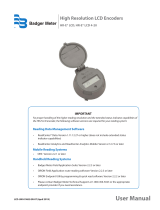
OTE:N Polarity must be observed when connecting the meter and the HR-RED wires: red (power/clock) to red,
green (data) to green, black (ground) to black.
Meter Cable with Flying Leads
RED - Power
GREEN - Data
BLACK - Ground
RED
GREEN
BLACK

Reading the Meter
Page 3 November 2017 DSY-UM-02471-EN-01
10. Make sure the wire ends are completely inserted into the connector, then crimp the connector using a crimping tool,
such as the Badger Meter crimping tool (PN: 59983-001). Do this for each pair of wires.
11. After the three wire pairs are connected, place the connected wires into the rectangular recess of the HR-RED base
and guide the meter cable through the slot at the bottom of the HR-RED.
12. Attach the HR-RED cover to the base with the seal screw from the installation kit.
OTE:N The Torx seal screw is designed to discourage and identify tampering.
13. Secure the entire length of cable from the meter to the HR-RED to complete a neat installation.
14. Check the system (meter, HR-RED wires) by running an adequate amount of water through the meter. Observe that
the HR-RED records correctly to conrm successful installation.
OTE:N If the meter is installed backwards, the encoder will not send a signal to the HR-RED. Check to make sure the flow
arrow on the meter is pointing in the direction of water flow.
READING THE METER
The HR-RED is a battery operated device. When attached to Badger Meter high resolution encoders or high resolution E-Series
Ultrasonic meters, the unit is designed to provide the same output resolution as the encoder, up to 9 digits for Badger Meter
products. It also displays the encoder serial number. To conserve battery life the HR-RED is awakened only when the internal
acoustic switch is activated. Tap the target circle on the front of the HR-RED display to activate the unit.
How the meter reading displays depends on the output resolution. The letters “RD” display to the left of the digits. Decimal points
are not displayed.
• 6 digit output or less: “RD“ and all digits appear at the same time, right-justified, and display for 10 seconds.
EXAMPLE of 6 digit meter reading:
<displays for 10 sec> RD 123456
• 7 or 8 digit output: “RD” appears by itself for 2 seconds. Then the complete meter reading (up to 8 digits) displays
for 10 seconds.
EXAMPLE of 8 digit meter reading
<displays for 2 sec> RD 1
<displays for 10 sec> 12345678
• 9 digit output: “RD” appears, followed by the first of the 9 digits, and displays for 5 seconds. Then the remaining 8
digits display for 10 seconds.
EXAMPLE of 9 digit meter reading
<displays for 5 sec> RD 1
<displays for 10 sec> 23456789
After the meter reading displays, the serial number of the encoder or meter displays. Then the HR-RED returns to sleep mode.

HR-RED, High Resolution Remote Electronic Display
www.badgermeter.com
Making Water Visible, Read-o-Matic, Recordall, RTR and Twist Tight are registered trademarks of Badger Meter, Inc. Other trademarks appearing in this document are the property
of their respective entities. Due to continuous research, product improvements and enhancements, Badger Meter reserves the right to change product or system specications
without notice, except to the extent an outstanding contractual obligation exists. © 2017 Badger Meter, Inc. All rights reserved.
Making Water Visible®
The Americas | Badger Meter | 4545 West Brown Deer Rd | PO Box 245036 | Milwaukee, WI 53224-9536 | 800-876-3837 | 414-355-0400
México | Badger Meter de las Americas, S.A. de C.V. | Pedro Luis Ogazón N°32 | Esq. Angelina N°24 | Colonia Guadalupe Inn | CP 01050 | México, DF | México | +52-55-5662-0882
Europe, Eastern Europe Branch Oce (for Poland, Latvia, Lithuania, Estonia, Ukraine, Belarus) | Badger Meter Europe | ul. Korfantego 6 | 44-193 Knurów | Poland | +48-32-236-8787
Europe, Middle East and Africa | Badger Meter Europa GmbH | Nurtinger Str 76 | 72639 Neuen | Germany | +49-7025-9208-0
Europe, Middle East Branch Oce | Badger Meter Europe | PO Box 341442 | Dubai Silicon Oasis, Head Quarter Building, Wing C, Oce #C209 | Dubai / UAE | +971-4-371 2503
Slovakia | Badger Meter Slovakia s.r.o. | Racianska 109/B | 831 02 Bratislava, Slovakia | +421-2-44 63 83 01
Asia Pacic | Badger Meter | 80 Marine Parade Rd | 21-06 Parkway Parade | Singapore 449269 | +65-63464836
China | Badger Meter | 7-1202 | 99 Hangzhong Road | Minhang District | Shanghai | China 201101 | +86-21-5763 5412
Switzerland | Badger Meter Swiss AG | Mittelholzerstrasse 8 | 3006 Bern | Switzerland | +41-31-932 01 11
ERROR MESSAGES
If an error is encountered, the display shows one of the following messages.
Message Description How to Correct
Check Wiring No meter/encoder appears to be connected.
Check the wiring connections between the
HR-RED and the encoder/meter.
Unknown Register
A response was obtained but not from a supported
register type.
Verify that the connected meter is a
supported type.
Framing Error
The data is corrupted. A stop bit did not occur where it
should have.
Check the integrity of the cable connections.
Parity Error An incorrect parity error check bit was received. Check the integrity of the cable connections.
SPECIFICATIONS
Operating Temperature –4…140° F (–20…60° C)
Encoder Compatibility HR-E, HR-E LCD, HR-E LCD 4-20, E-Series Ultrasonic meter
Dimensions L 4.651 in. (118 mm) × H 4.325 in. (110 mm) × W 2.017 in. (51 mm)
Weight 9 oz (255 g)
Display LCD, 8 characters, 0.25 inches high
Battery Life 10 years, 3.6V lithium battery
Construction High impact thermoplastic, weather and UV resistant
/