Page is loading ...

UF_iS4000_BA_02_1811
®
Badger Meter Europa GmbH
iSonic 4000
INSTALLATION AND
OPERATION MANUAL
November 2018

Content
UF_iS4000_BA_02_1811
Basic safety recommendations ............................................................................ 1
System description ............................................................................................... 2
Installation .............................................................................................................. 5
Installation with the sensor EchoPod DL-10 ............................................................... 5
Power connections ................................................................................................ 7
Auxiliary power .......................................................................................................... 7
Configuring input/output (I/O) ..................................................................................... 8
In- and output cable connection ....................................................................... 9
Programming ....................................................................................................... 10
Main Menu ............................................................................................................... 12
Meter Setup ................................................................................................... 12
Measurement................................................................................................. 13
Input and outputs ........................................................................................... 18
Clear total ...................................................................................................... 21
Communications ............................................................................................ 22
Miscellaneous ................................................................................................ 23
Info ................................................................................................................ 23
PIN ................................................................................................................ 24
Login ............................................................................................................. 24
Troubleshooting .................................................................................................. 25
Control LED ............................................................................................................. 25
Replace meter’s electronics ..................................................................................... 26
Technical data ...................................................................................................... 27
Program structure ............................................................................................... 29
Flow meter ModBus
®
register table 2017-06-29, Version “2.00” ..................... 35
iSonic conversation table ......................................................................................... 41
Rights ...................................................................................................................... 41
Wiring the iSonic 4000 meter to an ORION
®
cellular LTE endpoint .............. 42
Return of goods for repair ................................................................................ 43

Basic safety recommendations Page 1/43
UF_iS4000_BA_02_1811
Basic safety recommendations
Before installing or using this product, please read this instruction manual thoroughly.
Only qualified personnel should install and/or repair this product. If a fault appears,
contact your distributor.
Installation
Do not place any unit on an unstable surface that may allow it to fall.
Never place the units above a radiator or heating unit.
Route all cabling away from potential hazards.
Isolate from the mains before removing any covers.
Power connection
Use only the type of power source suitable for electronic equipment. If in doubt, contact
your distributor. Ensure that any power cables are of a sufficiently high current rating.
All units must be earthed to eliminate risk of electric shock.
Failure to properly earth a unit may cause damage to that unit or data stored within it.
Protection class
The device has protection class IP 67 and needs to be protected against dripping water,
water, oils, etc.
Setup & operation
Adjust only those controls that are covered by the operating instructions. Improper
adjustment of other controls may result in damage, incorrect operation or loss of data.
Cleaning
Switch off all units and isolate from mains before cleaning.
Clean using a damp cloth. Do not use liquid or aerosol cleaners.
Repair of faults
Disconnect all units from power supply and have it repaired by a qualified service person if
any of the following occurs:
• If any power cord or plug is damaged or frayed
• If a unit does not operate normally when operating instructions are followed
• If a unit exposed to rain/water or if any liquid has been spilled into it
• If a unit has been dropped or damaged
• If a unit shows a change in performance, indicating a need for service.
RoHs
Our products are RoHs compliant.
Battery disposal
The batteries contained in our products need to be disposed of as per your
local legislation acc. to EU directive 2006/66/EG.
Failure to adhere to these safety instructions
may result in damage to the product or
serious bodily injury.

System description Page 2/43
UF_iS4000_BA_02_1811
System description
Ultrasonic flow meter iSonic4000 is designated for flow measurements in open
channels and partially filled pipes and volume measurements of liquids in tanks. It is
possible to connect one level sensor (ultrasonic, pressure...) with 4-20 mA output to
the unit. Flows are consequently calculated from measured levels using pre-
programmed formulas for various primary flow elements (flumes, weirs) or from Q/h
table. Menu also enables the calculation of flow rateas in partially filled pipes and
angular open channels using Manning equation
• iSonic 4000 is IP67 device in robust wall mounted metal case, with large
graphic display.
• iSonic 4000 menu is operated with 3 x front panel high endurance buttons.
• iSonic 4000 is powered from external power AC 92 - 275V / 50..60Hz,
alternatively from external power 9-36 V (max 9 W), only possible with DC
version.
• User can be connected to iSonic 4000 via USB or Ethernet interface with
software Flow Meter Tool, which can be used for parameters setup and also for
datalogger download.
• iSonic 4000 have internal datalogger with 2 MB capacity for approximately
130 000 logged lines. It is possible to download logged data with software Flow
Meter Tool and save in *.csv, format to PC.
• Interfaces USB, Ethernet, ADE, RS232, ModBus RS485 / RS422 galvanic
isolated are mounted on board.
• The iSonic 4000 unit have 1 analog output 0/4..20mA and 2 galvanic isolated
pulse outputs.
Nameplate
Look at the device nameplate to ensure that the device is delivered according to
your order. Check for the correct supply voltage printed on the nameplate.

System description Page 3/43
UF_iS4000_BA_02_1811
System settings
Flow meter tool settings
Settings control panel

System description Page 4/43
UF_iS4000_BA_02_1811
Driver details

Installation Page 5/43
UF_iS4000_BA_02_1811
Installation
Installation instructions given in the following are to be observed in order
to guarantee a perfect functioning and a safe operation of the meter.
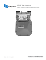
Installation with the sensor EchoPod DL-10
Installation of the sensor:
Screw the sensor into the stainless steel mounting bracket while using the
gaskets.
Sensor must be installed maximum 125 cm above the flume bottom (minimal
measured level) with a minimum of 5 cm distance above the maximal
measured level.
EchoPod DL-10 connection to the 4-20 mA input terminal (on the bottom side of
display board):
Viton Gasket
Sensor EchoPod
Max
125 cm
Min
5 cm

Installation Page 6/43
UF_iS4000_BA_02_1811
Mounting position of the iSonic ultrasonic sensor for manhole flume
Size
Max.
flow
Max.
water level
V-Mt
H-Mt
DN/Inch
l/sec
mm
mm
mm
100/4“
5
148
600
146
150/6“
16
227
600
197
200/8“
35
312
600
248
250/10“
63
395
700
298
300/12“
94
457
700
349
Mounting position of the iSonic’s ultrasonic sensor for parshall flume
Size
Max.
flow
V-Mt
H-Mt
DN/Inch
l/s
mm
mm
75/3
54
780
305
150/6“
114
780
406
230/9“
284
970
572
305/12“
598
contact
factory
contact
factory
455/18“
94
contact
factory
contact
factory
Sensor
MT
V
H

3Power connections Page 7/43
UF_iS4000_BA_02_1811
Power connections
Caution: For the 2 x M20 cable inlets only use flexible electric cables.
Use separate cable inlets for auxiliary power, signal and input/output
cables.
Auxiliary power
Warning: Do not connect meter under impressed mains voltage.
Take national applicable rules into account
Observe type plate (mains voltage and frequency)
Equipment shall be installed with an external means for disconnecting
it from each operating energy supply source. The disconnecting
means shall disconnect all current-carrying conductors.
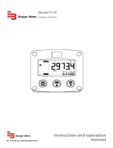
1. Slightly loosen the lower cover screws and both upper cover screws
completely. Open cover to the lower side.
2. Push auxiliary power cable through the upper cable inlet.
3. Connection as shown in the picture.
4. In the following close connection cover again firmly.
Power supply 92-275 VAC (50/60 Hz) Recommended cable size min. 0,75 mm²
Power supply 9-36 VDC (max. 9 W) Recommended cable size min. 0,75 mm²

3Power connections Page 8/43
UF_iS4000_BA_02_1811
RS-Interface
Dig. Out- and Input
Analog Output
Solid State Relay
RS-Interface
DIP switch
Display
Sensor input
Configuring input/output (I/O)
Input/Output Description Terminal
Analog output*
0 - 20 mA
4 - 20 mA RL < 800 Ohm
0 - 10 mA
7 (+)
8 (-)
9 (GND)
Digital output
1*
Open collector max. 10 kHz
• Passive max. 32 VDC, <100 Hz 100 mA, >100 Hz 20 mA
• Active 24 VDC, 20 mA
(can be powered by analog output if not used)
3 (-)
4 (+)
2*
Open collector max. 10 kHz
• Passive max. 32 VDC, <100 Hz 100 mA, >100 Hz 20 mA
• Active 24 VDC, 20 mA
(can be powered by analog output if not used)
1 (-)
2 (+)
3
Solid State Relais max. 230 VAC, 500 mA, max 1 Hz
(Function is linked with Output 2)
S1 and
S2
Digital input* 5 - 30 VDC 5 (-) and 6 (+)
RS interfaces*
RS232, RS485 and RS422 with ModBus
®
RTU.
Mode can be configured by DIP switches also termination
ON or OFF. I
n case of the RS485 the A wire has to be
connected to Y terminal and the B wire has to be
connected to Z terminal.
422 232 485
A RxD
B
Z TxD B
Y A
G (GND)
USB USB Device CDC (Host Mass Storage) Micro USB
Ethernet* Ethernet Interface connection RJ45 socket
* all marked in- and outputs are according to safety data TNV-1 IEC 60950-1
Auxiliary power
USB
Ethernet

3Power connections Page 9/43
UF_iS4000_BA_02_1811
In- and output cable connection
For the normal I/Os use shielded cables. Connect the shield of the cable
to one of the grounding screw. Recommended cable LiYCY size min.
0,14 mm².
Solid State Output
In case the second cable gland is used for the normal I/Os, use one
cable and cable gland for the power supply and solid state relay.
Recommended cable size min. 0,75 mm².
Caution: Use separate cable inlets for cables connected to the solid
state relay output and cables connected to the other
input/outputs.
In multiphase nets solid state relay should handle only the
same phase which is used for powering the meter

Programming Page 10/43
UF_iS4000_BA_02_1811
Programming
First screen – open channel
Volume designation
Volume value
Volume unit
Water level designation
Water level value
Length unit
Flow designation
Volumetric flow value
Volumetric flow unit
Icons
First screen – tank
Volume designation
Volume value
Volume unit
Water level designation
Water level value
Length unit
Icons
Second screen
Tag
Application version
Actual date & time
Current designation
Current value
Current unit
Programming is accomplished by using the three functional buttons ▲, ► and
Exit/Save.
You can move from the measuring mode to the programming mode by pressing
once the button Exit/Save
With the ▲ button you move downwards in the list. With the ► or Exit/Save button
you enter the menu or you move to the next submenu. The scrollbar on the upper
right shows at what position you are in the list. Go back from a submenu to the
upper menu press Exit/Save.
To select parameters or values from a list in a menu point, press key ▲ until the
requested parameter or value is displayed and confirm with key Exit/Save. The
current number in the list is marked by a ▪ on the left side. For example ▪
Pars.Flume2"
To change a parameter, enter the menu by pressing the button ► and the first
character flashes. Press the key ▲ to change the figure. Once you have changed
the desired figure, move to the next figure with the key ►. Confirm the new value
with key Exit/Save.
*Meaning of symbols on the display
menu header
scrollbar
indication of a submenu
submenu
Meter Setup
Main Menu

Programming Page 11/43
UF_iS4000_BA_02_1811
You get access to the individual menus through three programmable access levels:
Administrator, service and user level.
Access rights of the individual menu items are shown in the following with three
symbols:
For programming the access levels, see the chapter “passwords”. No passwords
were set at the factory.
Minor battery power
(Real Time
Clock)
W
Sensor warming
Device error
0
Sensor not connected
No keyword active
M
Sensor measuring
USB active
S
Simulation active
Administrator
Service
User

Programming Page 12/43
UF_iS4000_BA_02_1811
Main Menu
The following menu items are available to you in the main menu:
• Meter setup
• Measurements
• Inputs and outputs
• Totalizer reset
• Communication
• Miscellaneous
• Information
• Pin
Meter Setup
Application
Sellection between Tank and Open Channel measurement
Sensor
Interval
Setup of time measurement interval (s)– default
value is 1 second, bigger interval (e.g. 300
seconds) is set when unit is powered from
battery
WarmUpTime
Powering time of sensor (s) before
measurement, – for bigger intervals as 1
second, is set when unit is powered from
battery
LowerRangeValue
The minimal level value of used sensor =4 mA
in selected level units
UpperRangeValue
The maximal level value of used sensor =20
mA in selected level units
Offset
Level offset in selected level units, depends of
sensor mounting position.
Tank
Open Channel

Programming Page 13/43
UF_iS4000_BA_02_1811
Measurement
Length
Length units let you select among the units mentioned below.
Lengths values are automatically converted into the selected unit.
DecimalPlaces – set of the decimal places of the Length values
Flow Rate
Flow rate units let you select among the units mentioned below. Flow
rate values are automatically converted into the selected unit.
Volume
Volume units let you select among the units mentioned below.
Volume values are automatically converted into the selected unit.
Unit
Unit
L/s
Liter/Second
gal/s
Gallons/Sec.
L/min
Liter/Minute
g/min
Gallons/Min.
L/h
Liter/Hour
gal/h
Gallons/Hour
m³/s
Cubic meters/Sec.
MG/D
MegaGallon/Day
m³/min
Cubic meters/Min.
IG/s
UKG/Sec.
m³/h
Cubic meters/Hour
IG/min
UKG/Min.
ft³/s
Cubic Feet/Sec.
IG/h
UKG/Hour
ft³/min
Cubic Feet/Min.
Bbl/min
Barrel/Min.
ft³/h
Cubic Feet/Hour.
DecimalPlaces
– set of the decimal places of the Flow Rate values
Unit
ft
Feet
m
Meter
in
Inch
cm
Centimeter
mm
Milimeter
Unit
Unit
L
Liters
MG
MegaGallons
hL
HectoLiter
IG
Imperial Gallons
m³
Cubic Meters
bbl
Barrel
Ft³
Cubic Feet
Aft
Acre Feet
gal
U.S. Gallons
DecimalPlaces – set of the decimal places of the volume values

Programming Page 14/43
UF_iS4000_BA_02_1811
Equation
selection
Table
Q/hTable – is possible only from software
Flow Meter Tool
Exponential Eq
Exponential function Q= K h
exp
Contract.Weir
Contracted Weir
Suppress.Weir
Suppressed Weir
CipolettiWeir
Cipoletti Weir
VNotchWeir30°
V Notch Weir 30°
VNotchWeir45°
V Notch Weir 45°
VNotchWeir60°
V Notch Weir 60°
VNotchWeir90°
V NotchWeir 90°
ManningRect.
Manning Rectangle Flume
ManningPipe
Manning Pipe
Pars.Flume1"
Parschall Flume 1"
Pars.Flume2"
Parschall Flume 2"
Pars.Flume3"
Parschall Flume 3"
Pars.Flume6"
Parschall Flume 6"
Pars.Flume9"
Parschall Flume 9"
Par.Flume12"
Parschall Flume 12"
Par.Flume18"
Parschall Flume 18"
Par.Flume24"
Parschall Flume 24"
Par.Flume36"
Parschall Flume 36"
Par.Flume48"
Parschall Flume 48"
Par.Flume60"
Parschall Flume 60"
Manh.Flume4"
Manhole Flume 4"
Manh.Flume6"
Manhole Flume 6"
Manh.Flume8"
Manhole Flume8"
Manh.Flume10"
Manhole Flume10"
Manh.Flume12"
Manhole Flume12"

Programming Page 15/43
UF_iS4000_BA_02_1811
Equation Params
Open channel calculation
Volumetric flow is calculated from actual water level; actual water level is limited
by “Maximum water level”
Exponential Equation (general Parshall or Manhole flume)
Equation Q=K.Q
exp
Q – Volumetric flow [m³/s]
K – Coefficient [
]
h – Water level [m]
exp – Exponent [-]
Exponent value in for equation (Q= K h
exp
)
Exponent
Coefficient value in for equation (Q= K h
exp
)
Coefficient
Measured profile width (Weirs, Manning
equation)
Width
Rectangular profile slopes angle (Manning
equation)
Angle
Measured pipe Radius (Manning equation)
Radius
Water Surface Slope (Manning equation)
WaterSurfaceSlope
Surface Roughness coefficient (Manning
equation)
SurfaceRoughness
Maximum Water Level
MaximumWaterLevel
Flow Rate Upper Range Value
UpperRangeValue
Maximum
Water Level /SetDefaultVal. )
Set of the Maximum Water Level for the selected primary element
– the value
is possible
to edit further.
Upper Range Value /Calculate
Is calculat
ing the maximal Flow Rate value for Maximal Water Level - the
value is possible to edit further
– this parameter is used also for outputs
(
Upper Range Value=100% - full range)

Programming Page 16/43
UF_iS4000_BA_02_1811
Predefined flume
Equation [m³/s, m]
Maximum water level [m]
Parshall flume 1”
0.230
Parshall flume 2”
0.260
Parshall flume 3”
0.667
Parshall flume 6”
0.724
Parshall flume 9”
0.876
Parshall flume 12”
0.925
Parshall flume 18”
0.925
Parshall flume 24”
0.925
Parshall flume 36”
0.925
Parshall flume 48”
0.925
Parshall flume 60”
0.925
Manhole flume 4”
0.149
Manhole flume 6”
0.227
Manhole flume 8”
0.313
Manhole flume 10”
0.396
Manhole flume 12”
0.457
Contracted rectangular weir
Equation
Q – Volumetric flow [m³/s]
1.84 – Coefficient [
]
L – Width [m]
h – Water level [m]
Suppressed rectangular weir
Equation
Q – Volumetric flow [m³/s]
1.84 – Coefficient [
]
L – Width [m]
h – Water level [m]
Cipoletti weir
Equation
Q – Volumetric flow [m³/s]
1.84 – Coefficient [
]
L – Width [m]
h – Water level [m]

Programming Page 17/43
UF_iS4000_BA_02_1811
V-notch weir 30°
Equation
Q – Volumetric flow [m³/s]
g – Standard gravity 9.80665 [m/s²]
h – Water level [m]
V-notch weir 45°
Equation
Q – Volumetric flow [m³/s]
g – Standard gravity 9.80665 [m/s²]
h – Water level [m]
V-notch weir 60°
Equation
Q – Volumetric flow [m³/s]
g – Standard gravity 9.80665 [m/s²]
h – Water level [m]
V-notch weir 90°
Equation
Q – Volumetric flow [m³/s]
g – Standard gravity 9.80665 [m/s²]
h – Water level [m]
Manning equation: Q = 1/n R
h
2/3
I
1/2
A R
h
=A/P
Manning rectangular
Equation
Q – Volumetric flow [m³/s]
n – Gauckler-Manning coefficient [
]
L – Width [m]
h – Water level [m]
α – Angle [°]
I – Water surface slope [m/m]
Manning pipe
Equation
where
Q – Volumetric flow [m³/s]
n – Gauckler-Manning coefficient [
]
L – Width [m]
h – Water level [m]
I – Water surface slope [m/m]

Programming Page 18/43
UF_iS4000_BA_02_1811
Material
n[ ]
Material
n[ ]
Glass , PVC
0.010
Earth channel - weedy
0.030
Cement, concrete-steel,
tl
0.011
Natural streams – clean
0.035
Brick
0.015
Floodplains - light brush
0.050
Earth, smooth
0.018
Natural channels, poor
d
0.060
Earth channel – clean
0.022
Floodplains - heavy brush
0.075
Gravel, firm
0.023
Floodplains – trees
0.15
Earth channel – gravelly
0.025
Input and outputs
Analog output
Range
This parameter establishes the range of the analog output
signal: 0 to 100% (= full scale). The following current ranges are
available to you:
Analog output active
Analog output passive
Note:
In case that an error message is displayed, the current is set
according the programing of the “Alarm Mode” below.
In case that you select bidirectional operation, you can signal
flow direction via digital outputs.
Alarm Mode
This parameter configures the behaviour of the analogue output
during alarm conditions. Three options exist for this parameter:
OFF, 3.5 mA and 23 mA.
OFF: Analogue signal is based on flow rate and always within
the configured range.
3.5 mA: During alarm conditions, the analogue signal will be
3.5.
23 mA: During alarm conditions, the analogue signal will be
23mA.
For example, if the analogue range is 4 to 20 mA and the alarm
mode is set to 23 mA, then during a full scale flow alarm
condition, the analogue output current will be 23 mA
.
Compensation
Correction of the current value output.
Current output
0 to 20 mA
4 to 20 mA
0 to 10 mA
/