Page is loading ...

Operation Manual
FT128
Rev 2.4
For Software V2.4.x
FT128 FDCIE
MA350 April 2018

2
This page has deliberately been left blank.

Operation Manual
FT128 Rev 2.4
3
Table of Contents
1 Introduction .............................................................................................................................. 8
1.1 Overview ............................................................................................................................ 8
1.2 Definitions / Explanations ................................................................................................... 8
2 General Description ............................................................................................................... 11
2.1 The FT128 FDCIE ............................................................................................................ 11
2.2 Technical Address ............................................................................................................ 11
2.3 Presentation Number ....................................................................................................... 11
2.4 Com Loop Units ............................................................................................................... 11
2.5 Address and Mode ........................................................................................................... 12
2.6 Software (S/W) Versions .................................................................................................. 12
2.6.1 EBLWin .................................................................................................................... 12
2.6.2 Web-server Configuration ......................................................................................... 12
2.7 Applications...................................................................................................................... 12
3 Fire Detection Control & Indicating Equipment (FDCIE) ...................................................... 13
3.1 FT128 Specifications ........................................................................................................ 13
3.2 FT128 Limitations ............................................................................................................. 14
3.3 FT128 FDCIE Layout ....................................................................................................... 15
3.4 Front Display .................................................................................................................... 16
3.4.1 LED Indicators and Push Button ............................................................................... 17
3.4.1.1 Fire Brigade Panel Display and Control ................................................................. 17
3.4.1.2 FT128 Display CP Indicators ................................................................................. 18
3.4.2 The Display (LCD) .................................................................................................... 19
3.4.2.1 LCD Backlight ....................................................................................................... 19
3.4.2.2 Information Priority Order ...................................................................................... 19
3.5 System Information in the LCD ......................................................................................... 20
3.5.1 Fire Alarm Presentation in the LCD ........................................................................... 20
3.5.2 User Definable System Information ........................................................................... 20
4 Control Unit Options .............................................................................................................. 21
4.1 I/O Matrix 4582................................................................................................................. 21
4.2 AS1668 Fan Control Module ............................................................................................ 21
4.3 Zone Control & Indication Module ..................................................................................... 22
4.4 NZ Fire Brigade (LED) Mimic Board.................................................................................. 23
4.5 Occupant Warning System (OWS) ................................................................................... 24
4.6 Gaseous Extinguishing Control Module ............................................................................ 25
4.7 FT128 External Termination ............................................................................................. 26
5 New 19” Rack Cabinet & New Loop Modules ....................................................................... 28
5.1 Cabinet Overview ............................................................................................................. 28
5.2 Enclosure Components .................................................................................................... 28
5.3 Addressable COM Loop Display Modules ..................................................................... 29
5.4 I/O Field Modules............................................................................................................ 31
6 User Data & Access Levels ................................................................................................... 34
6.1 User Data ......................................................................................................................... 34
6.1.1 User Name ............................................................................................................... 34
6.1.2 Password ................................................................................................................. 34
6.1.3 Password for Web-server Access only ...................................................................... 35
6.2 Access Levels .................................................................................................................. 35
6.2.1 How to Log On ......................................................................................................... 35
6.2.2 Navigation / General Procedures .............................................................................. 35
6.3 User Level ........................................................................................................................ 36
6.3.1 User Level as specified in AS7240.2 ......................................................................... 36

Operation Manual
FT128 Rev 2.4
4
6.3.2 User Level 0 ............................................................................................................. 37
6.3.3 User Level 1 ............................................................................................................. 37
6.3.4 Access Level 2A ....................................................................................................... 37
6.3.5 User Level 2B ........................................................................................................... 38
6.3.6 User Level 3A ........................................................................................................... 39
6.3.7 User Level 3B ........................................................................................................... 39
6.3.8 User Level 4 ............................................................................................................. 39
6.4 Passwords / Change of Password .................................................................................... 40
6.4.1 Password for Web-server access only ...................................................................... 40
7 Technical Address / Presentation Number ........................................................................... 41
7.1 Technical Address for COM Loop Units ............................................................................ 41
7.2 Presentation Number ....................................................................................................... 41
8 Silence Alarm Devices ........................................................................................................... 42
8.1 Silence Alarm Devices (Inside Switch) .............................................................................. 42
8.2 NZ FB “Silence Alarms” Bulgin key (outside switch) .......................................................... 43
9 Disable / Re-Enable Alarm Devices ....................................................................................... 44
10 Silence Buzzer ....................................................................................................................... 45
10.1 Silence Buzzer by Open Door........................................................................................... 45
10.2 Silence buzzer by the "FB Bulgin Key" .............................................................................. 45
10.3 Buzzer ............................................................................................................................. 45
11 Disable / Re-enable Control Outputs .................................................................................... 46
12 “Disable” Button .................................................................................................................... 47
13 Door Open .............................................................................................................................. 48
13.1 Disable Routing Equipment with Door Switch ................................................................... 48
13.2 Silence Buzzer by Door Switch ......................................................................................... 48
14 Alarm Types ........................................................................................................................... 49
14.1 Pre-Warning ..................................................................................................................... 49
14.2 Fire Alarm ........................................................................................................................ 50
14.2.1 Entering Fire Alarm Menu during fire alarm (X1-X9) .................................................. 51
14.2.2 Test Mode Alarm ...................................................................................................... 52
14.3 Heavy Smoke Alarm / Heavy Heat Alarm .......................................................................... 53
14.4 Alert Annunciation Alarm (AA Alarm) ................................................................................ 53
14.5 Co-Incidence Alarm (2-Address / -Zone Dependence) ...................................................... 53
14.6 Delayed Alarm.................................................................................................................. 54
14.6.1 General Time Delay Applications .............................................................................. 54
14.6.2 Alarm Delay Facility (ADF) ........................................................................................ 55
14.7 Alarm Acknowledgement Facility (AAF) ............................................................................ 55
14.8 Quiet Alarm ...................................................................................................................... 56
14.9 Acknowledged and Isolated Alarm (for only NZ)................................................................ 57
14.9.1 Acknowledged Alarm ................................................................................................ 57
14.9.2 Isolated Alarm (for only NZ) ...................................................................................... 57
15 Alarm Reset ............................................................................................................................ 58
15.1 Pre-Warning Reset ........................................................................................................... 58
15.2 Fire Alarm Reset .............................................................................................................. 58
15.2.1 All (default) ............................................................................................................... 58
15.2.2 Single ....................................................................................................................... 58
15.2.3 Single Reset with Automatic Disablement ................................................................. 59
15.3 Test Mode Alarm Reset .................................................................................................... 59
15.4 Acknowledged and Isolated Alarm (for only NZ) Reset...................................................... 59
15.5 Heavy Smoke / Heat Alarm Reset .................................................................................... 59
15.6 Alert Annunciation Alarm Reset ........................................................................................ 59
15.7 Co-Incidence Alarm Reset ................................................................................................ 59

Operation Manual
FT128 Rev 2.4
5
15.8 Delayed Alarm.................................................................................................................. 59
15.9 Local Alarm Acknowledgement (LAA) Reset ..................................................................... 60
15.10 Quiet Alarm Reset ........................................................................................................ 60
16 Fault........................................................................................................................................ 61
16.1 Fault Messages ................................................................................................................ 62
16.2 Fault Acknowledge ........................................................................................................... 71
17 Commissioning an FT128 ...................................................................................................... 73
18 Software Download ................................................................................................................ 75
18.1 EBLWin Software Installation............................................................................................ 75
18.1.1 Installation procedure: .............................................................................................. 75
18.2 Download SSD ................................................................................................................. 77
18.2.1 SSD Download to the Control Unit ............................................................................ 78
18.2.2 User Definable Text Messages Download ................................................................. 79
18.3 Download Software (System Firmware) ............................................................................ 79
18.4 Software Versions ............................................................................................................ 81
19 Restart .................................................................................................................................... 82
19.1 Safe Shut Down ............................................................................................................... 82
19.2 Restart Table ................................................................................................................... 82
19.2.1 Explanation of Restart Codes ................................................................................... 83
19.3 During Restart .................................................................................................................. 83
19.4 Boot Menu........................................................................................................................ 84
20 Perform Monthly Test (H1) .................................................................................................... 85
21 Disable or Re-enable (H2) ...................................................................................................... 87
21.1 Disable Zone (H2/B1) ....................................................................................................... 88
21.2 Disable Zone / Address (H2/B2) ....................................................................................... 89
21.3 Disable Output (H2/B3) .................................................................................................... 90
21.4 Disable All Control, Ventilation, Extinguishing or Interlocking Outputs (H2/B4) .................. 91
21.5 Re-Enable Zone (H2/B5) .................................................................................................. 92
21.6 Re-Enable Zone / Address (H2/B6) .................................................................................. 93
21.7 Re-Enable Output (H2/B7)................................................................................................ 94
21.8 Re-Enable All Control, Ventilation, Extinguishing, Or Interlocking Outputs (H2/B8) ............ 95
21.9 Disable / Re-Enable Alarm Devices (H2/B9) ..................................................................... 96
21.10 Disable / Re-Enable Outputs for Routing Equipment (H2/B10) ...................................... 97
21.11 Disable / Re-Enable Alert Annunciation Function (H2/B11) ........................................... 98
22 Set Calendar and Clock (H3) ................................................................................................. 99
22.1 Daylight Saving Time ....................................................................................................... 99
23 Present System Status (H4)................................................................................................. 100
23.1 Disablement (H4/U1) ...................................................................................................... 100
23.2 Disablement by Time Channel (H4/U2) ........................................................................... 101
23.3 Sensor Values (H4/U3) ................................................................................................... 102
23.3.1 Explanation of the Sensor Values ........................................................................... 103
23.3.2 Algorithms .............................................................................................................. 103
23.4 Sensors Activating SERVICE Signal (H4/U4) .................................................................. 105
23.5 Technical Warning (H4/U5) ............................................................................................ 106
23.6 Event Log (H4/U6).......................................................................................................... 107
23.7 Version and Alarm Counter (H4/U7) ............................................................................... 108
24 Service (H5) .......................................................................................................................... 109
24.1 Calibration of Supervised Outputs (H5/A1) ..................................................................... 110
24.2 Sensitive Fault Detection Mode (H5/A2) ......................................................................... 111
24.3 Service Mode for COM-Loop (H5/A3) ............................................................................. 112
24.4 Display Current Consumption in Unit (H5/A4) ................................................................. 113

Operation Manual
FT128 Rev 2.4
6
24.5 Display Current Consumption on COM-Loop (H5/A5) ..................................................... 114
24.6 Display Statistics for COM Loop (H5/A6) ........................................................................ 115
24.7 Activate Address Setting Mode for DU (H5/A7) ............................................................... 116
24.8 Setup Wireless Detectors (H5/A8) .................................................................................. 117
24.9 End Setup Wireless Detectors (H5/A9) ........................................................................... 118
24.10 Show Information about Site Specific Data (H5/A10)................................................... 119
25 Acknowledge FAULTS (H6) ................................................................................................. 120
26 Perform ZONE TEST (Test Mode) (H7) ................................................................................ 121
27 Maintenance (H8) ................................................................................................................. 123
27.1 Disconnect / Re-connect COM loop (H8/S1) ................................................................... 123
27.2 Disconnect / Re-connect Zone Line Input (H8/S2) .......................................................... 124
27.3 Disconnect / Re-connect addressable zone interface input (H8/S3) ................................ 125
27.4 Acknowledge SERVICE Signal (H8/S4) .......................................................................... 126
27.5 Restore Weekly Average to Default (H8/S5) ................................................................... 127
27.6 Test of Alarm Devices (H8/S6) ....................................................................................... 128
27.7 Safe Shut Down of Control Unit (H8/S7) ......................................................................... 129
27.8 Activate Zone-Address in Alarm Mode (H8/S8) ............................................................... 130
27.9 Activate Output (H8/S9) .................................................................................................. 132
27.10 Reset activated output (H8/S10) ................................................................................. 133
28 Interlocking Outputs and Inputs (H9) .................................................................................. 134
28.1 Activated Interlocking Outputs/Inputs (H9/C1) ................................................................. 134
28.2 Activate Interlocking Output (H9/C2) ............................................................................... 135
28.3 Reset Interlocking Output (H9/C3) .................................................................................. 136
28.4 Disable Interlocking Output (H9/C4) ............................................................................... 137
28.5 Re-Enable Interlocking Output (H9/C5) ........................................................................... 138
29 Change Password (H10) ...................................................................................................... 139
30 FDCIE Maintenance ............................................................................................................. 140
30.1 Battery Maintenance ...................................................................................................... 140
31 How to Avoid Nuisance Fire Alarms ................................................................................... 141
32 Block Wiring Diagram .......................................................................................................... 143
33 Revision History .................................................................................................................. 147
33.1 Operation Manual Revisions Table ................................................................................. 147
33.2 Software Revision 2.4.4 .................................................................................................. 147
33.2.1 New Brooks Display and Field Modules .................................................................. 147
33.2.2 New and Enhanced Features .................................................................................. 147
33.2.3 Corrected bugs in FT128 ........................................................................................ 149
Table of Figures
Figure 1 Connection diagram of FT128 ............................................................................................ 11
Figure 2 Standard FT128 ................................................................................................................. 15
Figure 3 The FT128 Front, FBP (upper black part) and CP (lower grey part) ................................... 16
Figure 4: AS1668 Fire Fan Control Display ...................................................................................... 21
Figure 5 Zone Control & indication Display....................................................................................... 23
Figure 6 NZ Fire Brigade Mimic Sample Drawing ............................................................................. 24
Figure 7 Occupant Warning System Display .................................................................................... 24
Figure 8 Gas Extinguishing Display Layout ...................................................................................... 26
Figure 9 SUB836 Adaptor Board...................................................................................................... 27
Figure 10 SUB835 external Terminal Board ..................................................................................... 27
Figure 11 FT128 Mounted in Small 19" Rack Enclosure ................................................................... 28
Figure 12 3U Ancillary Modules Face Plate (CB681) ........................................................................ 29
Figure 13: 1204 Power Monitor Module............................................................................................ 29

Operation Manual
FT128 Rev 2.4
7
Figure 14: 1205 Zone Control Module .............................................................................................. 29
Figure 15: 1206 Fan Control Module ................................................................................................ 30
Figure 16: 1211 Damper Control Module ......................................................................................... 30
Figure 17: 1207– 8 Key / 8 LED Control & Display Module ............................................................... 30
Figure 18: 1208 - 4 Key / 8 LED Control & Display Module............................................................... 30
Figure 19: 1209 – 8 LED Display Module ......................................................................................... 30
Figure 20: 1210 – 6 LED Pump Status Module................................................................................. 30
Figure 21 SUB997 Single Supervised Input / Single Relay Output.................................................... 32
Figure 22 SUB983 4 Supervised Input / 4 Supervised 24V Output ................................................... 32
Figure 23 SUB994 Four Supervised inputs / four latching relay outputs ............................................ 32
Figure 24 SUB991 8 Non-supervised Input / 8 Relay Output ............................................................ 32
Figure 25 Field Module Enclosure BAFMES .................................................................................... 33
Figure 24 Run Software in compatibility mode ..................................... Error! Bookmark not defined.
Figure 27 FT128 General Arrangement for 19” Rack System ......................................................... 144
Figure 28 FT128 Standard Block Wiring Diagram .......................................................................... 145
Figure 29 NZFT128 Block Wiring Diagram for NZ .......................................................................... 146
List of Tables
Table 1 Definitions and Explanations ................................................................................................. 8
Table 2 FT128 specifications ........................................................................................................... 13
Table 3 FT128 Limitations ............................................................................................................... 14
Table 4 Fire Brigade Panel LED Indicators and Push Buttons .......................................................... 17
Table 5 LED indicators on Control Panel (CP) ................................................................................. 18
Table 6 Control Panel push buttons ................................................................................................. 19
Table 7 LCD priority order ................................................................................................................ 19
Table 8 Indicators and buttons in 1668 module ................................................................................ 22
Table 9 Zone control LEDs and Buttons ........................................................................................... 23
Table 10 OWS controls and indications............................................................................................ 25
Table 11 Gas Front Status LED Indication and flash Pattern ............................................................ 26
Table 12 Levels of access ............................................................................................................... 36
Table 13 Access levels and users .................................................................................................... 36
Table 14 Latest Software Versions for FT128 .................................................................................. 81
Table 15 Data affected by restart ..................................................................................................... 82
Table 16 Other Drawing Lists......................................................................................................... 143

Operation Manual
FT128 Rev 2.4
8
1 Introduction
1.1 Overview
FT128 Operation Manual is a document intended to be used by the end user and the fire
brigade personnel, as well as the service / commissioning engineers, who should read this
document in conjunction with the FT128 Technical / Programming manual, since most of
the information in one of the documents is not found in the other document and vice versa.
The block wiring diagram of a standard FT128 system and general arrangement are shown
in Chapter “Block Wiring Diagram” on page 143.
Due to continual development and improvement, different S/W versions might be found.
This document is valid for software (firmware) version 2.4.x. On the date of printing this
manual x=4.
The software version is the firmware (system software) downloaded in to the control unit
via PC windows based software e.g. EBL128 V2.4.x. The latest system software is factory
downloaded in FT128 before delivery. However, software may be upgraded to a newer
revision on site.
The software version is dependent on the country where the control panel to be installed,
that is due to the variations in the standard in each country. Two separate software
versions are available, Australian (AU) and New Zealand (NZ).
The PC software is a windows based software EBLWin which has to be installed in your
PC and must have a version number similar to the software (system software) version
number i.e. version V2.4.x. The EBLWin is used to download the firmware and the Site
Specific Data (SSD) into the FDCIE.
Only the first two digits must be identical in the system software and the EBLWin version
number i.e. 2.4.x (x = minor modifications).
Note: Regarding upgrade from S/W version 1.x.x to version 2.x.x see chapter “Software
(S/W) download”, page 79 .
1.2 Definitions / Explanations
Definitions / explanation and abbreviations are used frequently in this document and are
shown in the following sections.
Table 1 Definitions and Explanations
Device or function Description
Alarm points
Units, which can generate a fire alarm in FT128, i.e. analogue
detectors (sensors), manual call points, conventional detectors,
etc.
Smoke detector
Analogue or conventional photoelectric smoke detector
Sensor
Sensor = Analogue detector
Analogue detector
Contains an A/D-converter. The FT128 picks up the digital
values ("sensor values") for each detector individually. All
evaluations and "decisions" are then taken by alarm algorithms
in the FDCIE. As from version 2.0.x the latest detector
generation (440x) can be used in "Advanced mode", i.e. the
alarm algorithms are in the detector instead. Analogue
detectors are
addressable, an address setting tool 4414 is used
for the detector's COM loop address and mode settings.
An analogue detector has to be plugged in an Analogue
Sensor Base (ASB).
Analogue Sensor Base (ASB)
An analogue detector is plugged in an ASB, which is
connected to the COM loop (see below).

Operation Manual
FT128 Rev 2.4
9
Conventional detector
A detector with only two statuses, i.e. normal or fire alarm. The
detector has a "closing contact" and a series alarm resistor
(560 Ohm). Normally plugged in a conventional detector base
CDB (see below), which is connected to a conventional zone
line input. Some types are water proof types and cannot be
plugged in the standard base, it is connected directly to a zone
line. An end-of-line device has to be connected in the last unit
on the conventional zone line.
Conventional Detector Base (CDB)
A conventional detector is plugged in a CDB, connected to a
conventional zone line input.
Addressable
A unit with a built-in address device. Each unit is individually
identified, handled and indicated in the FDCIE. (The unit can
be an I/O unit with a zone line input, to which one or more
conventional "alarm points" can be connected.)
Conventional zone line input
Input intended for one or more conventional alarm points. End-
of-line device in the last alarm point on the zone must be fitted.
Output unit
Addressable unit with programmable control outputs.
Connected to the COM loop (see below).
Output / Control output
Defined or programmable function. Relay output or voltage
output (supervised or non-supervised), in the FDCIE or an
output unit connected to the COM loop.
Short circuit isolator (ISO)
Addressable unit for automatic disconnection of a COM loop
segment (see below) in case of short circuit on the loop. As per
AS1670.1, one isolator is required every 40 alarm points on the
COM loop or every zone.
Remote Display Unit (RDU)
Addressable unit (RS485 line) for fire alarm presentation
(including user definable alarm text), alert annunciation, etc.
Two types are normally used: External presentation unit 1728
(EPU) and alert annunciation unit 1736 (AAU).
Note: An optional RS485 communication module (chip) must
be fitted in order to interface up to 8 display units (1728 /
1736), end of line resistor must be set via a jumper link on the
last unit. For more information, refer to the technical manual of
1728 and 1736
COM loop
Loop = twisted pair cable, to which all the addressable units
can be connected. Starts in the FDCIE and returns back to the
FDCIE.
Control Unit / C.U. / FDCIE
Control Unit = Fire Detection Control and Indicating Equipment
(FDCIE) = Unit to which the alarm points are connected (via
e.g. a COM loop). Indicates on the front fire alarm, fault
conditions, etc.
Fire Brigade Panel (FBP)
The fire brigade panel is an integral part of FT128 intended for
fire alarm, fault and disablement presentation, etc. The FBP
compromises the top part of the front display. Intended for fire
alarm presentation and for the fire brigade personnel.
Control panel (CP)
A part of the FT128 front display, intended for the building
occupier / officer, service personnel, etc., to "communicate"
with the Control Unit. It comprises the bottom part of the front
display.
Nuisance alarms
False or unwanted alarms
LED
LED (Light Emitting Diode) = Yellow, green or red optical
indicator ("lamp").
External Indicator / RIL
A unit with a red LED connected to a base (ASB / CDB) or a
detector with an output for a remote indicator RIL.
Lit when the built-in LED in the detector / base is lit.
Display / LCD
LCD (Liquid Crystal Display) = Display (in the FDCIE or Display
unit) for presentation of fire alarms, fault messages, etc.
Normally alphanumeric characters and backlight.
Door open (Door / Key switch)
In FT128 there is a door switch, which is activated when the
FDCIE door is open. Door open feature can be used to disable

Operation Manual
FT128 Rev 2.4
10
fault, strobes or OWS.
An open door is indicated in the LCD (i.e. an "open door" icon).
Site Specific Data (SSD)
The SSD is unique for each installation. All alarm points,
presentation numbers, user definable alarm texts,
programmable outputs, etc. are created in the PC program
EBLWin and also downloaded in FT1028 unit(s) with EBLWin.
Software (S/W) / Firmware / System
program
The software (S/W) – also called Firmware and System
program –
makes the control unit (the microprocessor) work. It
is factory downloaded but another / new version can be
downloaded in FT128 on site using the PC program EBLWin.
EBLWin
PC program used to create and download the SSD in FT128
unit(s). Also used to download another / new software version.
Can be used during commissioning / maintenance of the
FT128 system (auto address, check loop, acknowledge faults,
etc.)
Web-server
The Web-server is used to transfer FT128 information to other
systems e.g. Nurse call systems, as well as remote control via
a PC (browser) and an intranet / internet. The Web-server is
configured via the PC tool EBLWin.

Operation Manual
FT128 Rev 2.4
11
2 General Description
2.1 The FT128 FDCIE
FT128 is a microprocessor controlled intelligent fire alarm Control and Indicating
Equipment (FDCIE) intended for Analogue addressable smoke and heat detectors as well
as conventional detectors and manual call points. Programmable inputs, control outputs
and I/O units are available. Up to 255 addresses can be connected to FT128 loaded with
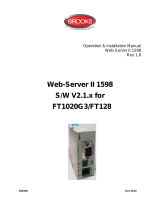
EBL128 system software ≥ V2.0.x. Figure 1 below presents an overview of the FT128
system.
FT128 is certified to the Australian Standard AS7240.2 and AS7240.4 and NZS4512:
2003. The Fire Brigade Panel controls and indicators are incorporated as part of the front
fascia and conform to AS4438.3.
Figure 1 Connection diagram of FT128
2.2 Technical Address
The technical number, NNN, is used when programming all units connected to the COM
loops. Technical number is also used to identify which unit has generated a fault.
2.3 Presentation Number
Each fire alarm point / input / zone has a presentation number, NNN-NN. The presentation
number is shown in the FDCIE display to identify the point / zone activating fire alarm.
2.4 Com Loop Units
Addressable COM loop units are connected directly to a COM loop. Right click on the tree
view as on Figure 2 to add new COM loop units.

Operation Manual
FT128 Rev 2.4
12
2.5 Address and Mode
Most of the addressable units must have both address and mode set. This is done in
different ways for different units, for example address setting tool 4414, DIP switches,
jumpers, or via the FDCIE display. For more information, please read the Technical
Description for each unit respectively.
2.6 Software (S/W) Versions
Due to continual development and improvement, different S/W versions can be found. The
control unit S/W can be updated on site.
2.6.1 EBLWin
The PC program EBLWin is used for programming and commissioning, i.e. to:
• Auto-generate, i.e. to identify the units connected on the COM loop and create
default settings, which can be edited, saved and used as a Site Specific Data
(SSD).
• Create / download / upload (backup) the site specific data (SSD)
• Download new S/W version (firmware), settings, conventions, configurations,
FT128 data / etc.
• Create / download the user definable text messages (alarm text) shown in the
display in FT128 / RDU’s.
• Download software to the Web-server.
• Create and download the Web-server configuration.
• See alarms, faults, disablements, etc. and reset, acknowledge fault, re-enable.
EBLWin must have the same version no. as the system software EBL128 S/W version,
e.g. 2.4.x. (x indicates only a small correction and is not required to be the same). Old
SSD files can be opened in a newer (higher) version of EBLWin, then edited, saved and
thereafter downloaded to FT128. If a backup is required, use the same EBLWin version as
the EBL128 S/W version.
EBLWin key 5094 is a USB unit that has to be plugged in the PC to log on to the FDCIE.
2.6.2 Web-server Configuration
A tool used for configuration of the Web-server II (1598), it is part of the EBLWin PC
program, see above.
2.7 Applications
The FT128 is intended for small and medium installations. The intelligent control unit offer
the system designer and end user a technically sophisticated range of facilities and
functions.
Programming with the PC program EBLWin and commissioning the system is very easy.

Operation Manual
FT128 Rev 2.4
13
3 Fire Detection Control & Indicating Equipment
(FDCIE)
3.1 FT128 Specifications
Table 2 FT128 specifications
Item
Specifications
Mains Voltage 230V
AC
(176-264), 1.6A
System Voltage 24
V
DC
@ 1.6A
Current Consumption
Quiescent / alarm current is dependent on other
equipment fitted in FT128
, type and number of
expansion boards, connected external equipment, etc.
1
.
Ambient Temperature (⁰C) Operating 0 to + 40, Storage -40 to +70
Ambient humidity (%RH) Maximum 90, non-condensing
Size (mm)
Standard
Small cabinet 630H x 450W x 210D (with door closed)
Large cabinet 920H x 450W x 210D (with door closed)
2
19” Rack
3
Small cabinet 678H x 600W x 250D
Large cabinet 1078H x 600W x 250D
Enclosure Material 1.5 Zinc anneal steel
Enclosure Colour Oyster, powder coated, ripple finish
Approvals AS7240.2, AS7240.4, AS4428.3 and NZS4512
Standard Inputs / Outputs
4
Single COM loop, can connect up to 255 devices
Single programmable input I0
Two programmable Supervised voltage outputs, 0.75
Amp each
One programmable relay outputs, contact rating 2 Amp
5
One programmable clean contact (N/O or N/C) inputs
One non-programmable relay outputs for ASE (fault)
Two x 24V outputs for Web server, ASE, remote display
units, external applications, etc.
Expansion Boards
6
Max. 4 of 4580, 4581 or 4583 or any combination
7
I/O Matrix 4582 board Max. 8 if no expansion boards fitted.
1
Refer to the technical manual and the current calculation spread sheet.
2
A combination of large and medium enclosures can be used to fit more options.
3
Will be available end of second quarter 2018
4
Refer to FT128 block wiring diagram, drawing no. F665
5
Voltage output V0 is used to provide 2 additional sets of relay contacts on the external termination board SUB835.
6
Expansion boards are internally connected to the COM loop.
7
It is allowed to have up to 4 boards of any type with warning for 4583 if more than 2 are added. Available only in V2.1.0 and
higher.

Operation Manual
FT128 Rev 2.4
14
3.2 FT128 Limitations
In addition to increasing the number of the COM loop units to 255 in software ≥ V2.0, other
limitations have also been increased as well as adding new types. The following table lists
some of the limitations in V2.4.x software.
Table 3 FT128 Limitations
Item
Maximum
number
General fire alarm via programmable input 256
External fault via programmable input 50
Inputs 128
Outputs (All kinds of outputs) 200
Trigger conditions (in all the control expressions) ~1000
Technical warnings 50
Short circuit isolators 128
3379 (or future 4479) 50
Interlocking Combinations.
100
Presentation numbers / alarm points that can be presented in the
display(s) in case of fire alarm (zone/zone address)
256
Presentation numbers that can be programmed (loop units) 255
Detectors and/or manual call points (alarm points) 512
Zones that can be programmed 99
Faults 200
Disabled alarm points (zone/address) + Disabled COM loops
(Zone/address disabled via time channel not included.)
200
Disabled outputs (Control outputs disabled via menu H2/B3 and Alarm
devices disabled via menu H2/B4 not included.)
100
Disabled interlocking outputs
(Interlocking outputs disabled via menu H2/B3 not included.)
100
Sensors activating SERVICE signal 100
Max. number of expansion boards 4580, 4581 & 4583
8
4
Max. number of LAA zones (AAM)
(Max. 5 detectors/zones per LAA zone.)
50
Max. number of I/O Matrix boards with expansion boards.
Number without expansion boards.
4
8
8
Expansion boards are internally connected to COM loop 0, ensure total number of expansion boards and I/O matrix boards
connected to the COM loop does not exceed 4. Software 2.1.1 allows to use 4 expansion boards.

Operation Manual
FT128 Rev 2.4
15
3.3 FT128 FDCIE Layout
Figure 2 Standard FT128
The FT128 control and indicating equipment (FDCIE) is housed in a metal cabinet powder
coated oyster colour. The cabinet has an inner and outer door. The outer door is fitted with
a 003 key to provide access level 1 and is made of tinted high impact plastic and allows
easy viewing of all indicators and controls.
Access to the inner door is gained by first opening the outer door which then provides
access to the inner door fixing screws.
Opening the inner door allows access to the control unit hardware for the purpose of
maintenance or servicing.
Figure 2 shows the standard FT128 in the medium size cabinet fitted with only one option
(OWS). Other options e.g. AS1668 Fan Control, Zone Control, etc, can also be fitted
depending on the space available on the front face plates.
Each FT128 has the following basic configuration:
• Metal cabinet powder coated oyster with smoky acrylic door as shown in Figure 2,
larger cabinet sizes also available.
• Main board (4556). See Dwg. F665.
One COM loop (0) to which the loop units are connected. See Dwg. F665.
Two programmable supervised voltage outputs (S0-S1). See Dwg. F665.
One programmable relay output (R0). See Dwg. F665.
One non-programmable relay output for routing equipment (Fault condition
output for Fault tx). See Dwg. F665.
One programmable inputs (I0). Supervised when required. See Dwg. F665.

Operation Manual
FT128 Rev 2.4
16
Two 24 V DC outputs (power supply outputs for routing equipment and
external equipment). See Dwg. F665.
A socket for an optional Communication module (RS485 transceiver
component) 4552, which will provide an RS485 interface (serial line) for up to
eight Display Units. See Dwg. F665.
RS232 interface ("D" connector) for a PC with EBLWin. See Dwg. F665.
RS232 interface for a Web-server 1598. See Dwg. F665.
24 V DC power supply output for a Web-server II 1598. See Dwg. F665.
• Built-in power supply and space for back-up batteries. See Dwg. F665.
• Space for optional expansion board holder. Up to four expansion boards can be
mounted in the holder.
• Space and mounting bracket for different routing equipment (optional).
• DIN rail for Web-server II 1598 (optional.
3.4 Front Display
Figure 3 The FT128 Front, FBP (upper black part) and CP (lower grey part)
An alphanumeric display is provided to view which alarm point / zone has generated a fire
alarm(s). In the alphanumeric display (LCD, 2x40 characters), the information displayed
on the first row depends on how many alarm points / zones have generated fire alarm (and
also convention). On the second row, a user definable text message is shown for an alarm
point or a zone, if programmed. See chapter "Fire alarm", page 50.
Fire services personnel use the FBP in FT128 to take operational control of the system.
The CP is used to "communicate" with FT128, e.g. for commissioning, monthly tests,
maintenance, etc. Access codes for different users and access levels are required. A
keypad is used to get access to the menu tree, i.e. the main and sub menus for data input
/ output and manoeuvres, etc. The CP also holds several system status LEDs.

Operation Manual
FT128 Rev 2.4
17
3.4.1 LED Indicators and Push Button
LED’s and push buttons are contained on the front panel display and are described in the
tables below. See also Figure 3 above, for the LEDs and push buttons.
3.4.1.1 Fire Brigade Panel Display and Control
Table 4 Fire Brigade Panel LED Indicators and Push Buttons
No. Label Colour Indicating / Action
L1 Fire
5 x Red Fire alarm, Quiet alarm, etc. See
Alarm
Types
page 49
9
L2 Alarms queued
2 x Red More than one unit / zone has generated fire
alarm.
Use push button "Alarms queued" (P1) to
scroll amongst the alarm points (zone-address).
L3 Extinguishing
Red Output(s) for extinguishing equipment
10
activated
(or a programmable input ty
pe "Extinguishing" is
activated).
L4 Ventilation
Yellow Output(s) for fire/smoke ventilation equipment
10
activated (o
r a programmable input type
"Ventilation" is activated.)
L5 Fire Brigade TX Red
Output for “Fire alarm” for Fire Brigade TX (routing
equipment)
activated. Or a programmable input(s)
type "Activated routing equipment" is activated. Or
t
est of routing equipment in progress (see menu
H1).
L6 Operation
Green
Power on, i.e. the FT128 power supply (switch
mode power supply and/or batteries) are
connected and working properly.
P1 Alarms queued BLACK
Used, when LEDs "Alarms queued" (L2) are lit, to
scroll/browse through the queued alarms (zones).
P2 Silence buzzer Yellow Used to silence the buzzer in FT128
P3
Silence Alarm
devices
Red
Used to silence
devices configured as “Alarm
devices” such as sounders or OWS (i.e. to "reset"
outputs for alarm devices).
11
P4 Reset
Green Used to reset the fire alarm(s), has to be pressed
for > 0.5 Secs
P5 Disable
Yellow Used to disable active alarm(s), all outputs of the
device or zone in alarm will be disabled.
9
In the New Zealand convention also "Acknowledged alarm" (ACK).
10
L3, L4 and L5 can as an alternative be programmed to indicate when a programmable input is activated, i.e. input trigger
condition "Extinguishing system released", "Activated fire ventilation" and "Activated routing equipment" respectively (e.g. L5
can be turned on when a programmable input is activated by an activated routing equipment output). L5 is turned on until all
fire alarms are reset.
11
Via EBLWin can be set if the alarm devices are to be continuously off / disabled or re-sound for a new alarm.

Operation Manual
FT128 Rev 2.4
18
3.4.1.2 FT128 Display CP Indicators
Table 5 LED indicators on Control Panel (CP)
NO. LED
Indicator
Colour Indicating
L7 General fault Yellow
Fault(s), i.e. not
acknowledged fault(s) and/or
acknowledged but not corrected fault(s).
L8 Disablements Yellow
Something is disabled / disconnected via a menu,
via a disable switch or via a button in the zone
control module if fitted.
L9 Test mode Yellow
One or more zones are in "test mode" (see menu
H7).
L10 Door open Yellow A door is open in FT128 control panel.
L11
Fault TX
activated
Yellow
One or more non-acknowledged faults:
•
Output for fault TX (routing equipment) is
activated.
•
Test of routing equipment in progress (see
menu H1).
•
Sensitive fault detection mode is on. See
menu Sensitive Fault Detection Mode
(H5/A2).
L12 Service Yellow
One or more sensors have reached the service
level. See menu H4/U4.
L13
Fault /
Disablements
Alarm devices
Yellow
Steady light: output(s) type “Alarm device” is / are
disabled.
Flashing light: output(s) type “Alarm device” have
generated fault(s)
12
.
L14 System fault Yellow
FT128 is not running due to S/W, CPU or memory
fault)
13
.
L15
Fault /
Disablements
Fire Brigade
TX
Yellow
Steady light: Output(s) for "Routing equipment"
disabled via menu H2 / B5 or via open door.
Flashing light: Routing equipment power supply
output or supervised outputs type “Routing
equipment” have generated fault(s)
14
.
L16
Fire Brigade
TX delay
Yellow
The Alert Annunciation function is enabled, i.e. the
time channel controlling this function is "on".
15
12
This is also valid when FT128 has no "contact" with a unit with such an output, e.g. 4477, 3379, 3364, etc.
13
The LED is turned on during restart and stays on for restart code other than 00, 03 or 25 until the fault is acknowledged.
14
This is also valid when EBL128 has no "contact" with a unit with such an output, e.g. an I/O unit 3361, etc.
15
The Alert Annunciation function is described in the FT128 Technical / Programming Manual, chapter "Alert annunciation". The
LED "L16" will be "on" if the AA function is enabled for at least one alarm point / zone. Normally, only one time channel used
for this function but two or more channels can be used. The AA function can, as an alternative, be continuously "on".

Operation Manual
FT128 Rev 2.4
19
Table 6 Control Panel push buttons
Key/push button Operation/function
P6
Fault acknowledge
(yellow)
Used to acknowledge the faults shown in menu H6. Also
used to acknowledge
SERVICE signal, see menu
H8/S4.
16
P8 Access (white)
Used to log on, i.e. to get access to the menu tree (via an
access code) to carry out disablements, etc. In
conjunction with a fire alarm, some information is
available and some actions are possible to perform via
the "Fire alarm menu" (X1-X9) without log on, see chapter
"Fire alarm", page 50 .
P9 Return (white)
Used to stop input of data, leave a menu ("one step up")
and to log off.
1 – 9 and 0 Numeric keys for the figures 0-9.
C Used to clear /delete just written data.
A Used to accept a menu and accept input of data.
← →
↑ ↓
Left / right keys are used to move the cursor in a menu.
Up / down keys are used to scroll between the menus.
3.4.2 The Display (LCD)
3.4.2.1 LCD Backlight
When the information above is shown in the LCD, the backlight is OFF.
As soon as any other information (see below) is shown in the LCD, the backlight is turned
ON.
The LCD backlight will remain on even during loss of the main power source.
3.4.2.2 Information Priority Order
When the FT128 is in normal operation (quiescent state), i.e. no fire alarms, no faults, no
disablements, no service signals, no zones in test mode, no activated interlocking in /
outputs, and/or Alert Annunciation function not enabled, only the LED "Operation" should
be lit and some system information is shown in the LCD.
The LCD information priority order is shown in Table 7 below.
Table 7 LCD priority order
16
In New Zealand convention, the “Fault acknowledge” button is used to acknowledge a Fire alarm, i.e. the alarm abbreviation
"ALM" in the LCD is changed to "ACK".
Priority Event
1
Fire alarms:
• Fire alarm
• Heavy smoke/heat alarm
• Alert Annunciation (AA) alarm
2 Quiet alarm

Operation Manual
FT128 Rev 2.4
20
3.5 System Information in the LCD
The display (LCD) of FT128 in normal operation and in quiescent state will show the
following information:
DD-MM-YYYY = (Date) Day-Month-Year
hh:mm = (Time) hours:minutes
[i] = Will only be shown in case of one or more Technical Warnings in the system.
3.5.1 Fire Alarm Presentation in the LCD
1. Field for the first alarm point or zone in alarm. By scrolling each alarm will be
shown in this field.
2. Field for the most recent (last) zone in alarm.
3. Field for total number of zones in alarm.
4. Field for alarm text. (User definable.)
3.5.2 User Definable System Information
The information on the bottom row can be created via EBLWin, i.e. it is user definable. In
total 40 characters.
17
The AAF function is used in conjunction with an AAM Control (3340) and the new Local Alarm Acknowledgement
LAA module.
3 Co-incidence alarm
4 Delayed alarm
5 Pre-warning
6 Test mode alarm
7 LAA (AAF) alarm
17
8
New Zealand convention only:
“Routing equipment left isolated”
9 Fault (not acknowledged)
10 Disablement
11 Zones in "Test mode"
12 Interlocking input / output active
13 System information
User programmable information text.
[ i ]
hh:m
* * * FT128 * *
DD-MM-YYYY
/