Page is loading ...

Operation / Technical Manual
Standalone OWS
Rev 2.4
Occupant Warning System
BOWS020W, BOWS060W &
BOWS120W
MA380 December 2019

OWS Standalone Manual
MA380 - Rev. 2.4
1
Document History
Issue Date Description Written By Checked By
Draft 0 25 Sep 2008 Original Draft Document. Wallace Zhong Anis Shenouda
Rev 1 17/08/2009 Update & finalise draft issue W.Z. / A.S. A. S.
Rev 2 01/05/2011
Add current calculation, add 20W model and
update DIP switch table
W.Z. / A.S. A.S.
Rev 2.1 22/08/2013 Minor update, add photos and updated drawings A.S. A.S.
Rev 2.2 23/03/2016
Add table 3 for voice messages and update
drawings
A.S.
Rev 2.3 07/09/2017 Update SUB862 to use SUB999 instead Edwin Thein A.S.
Rev 2.4 16/12/2019 Update drawings, SUB999 and Vic address A.S. A.S.

OWS Standalone Manual
MA380 - Rev. 2.4
2
Table of Contents
1 INTRODUCTION ........................................................................................................................................... 4
1.1 Overview ............................................................................................................................................. 4
1.2 Features .............................................................................................................................................. 4
1.3 Specifications ...................................................................................................................................... 5
2 OPERATIONS ............................................................................................................................................... 6
2.1 Display Layouts .................................................................................................................................. 6
2.2 Mode of Operation .............................................................................................................................. 6
2.2.1 Isolate mode ........................................................................................................................... 6
2.2.2 Automatic mode ..................................................................................................................... 6
2.2.3 Manual mode ......................................................................................................................... 7
2.3 Fault Indications .................................................................................................................................. 7
2.4 Auxiliary Audio Input ........................................................................................................................... 7
3 PLANNING ..................................................................................................................................................... 8
3.1 System Components .......................................................................................................................... 8
3.2 Monitored Inputs and Outputs ........................................................................................................... 8
3.3 OWS Main Control Board SUB860 ................................................................................................... 9
3.3.1 OWS Tones and Messages .................................................................................................. 9
3.3.2 Cables Terminations ............................................................................................................ 10
3.3.3 On-Board LED indications ................................................................................................... 11
3.4 Optional OWS 4 Zone Splitter Board fits 4580 Brackets - SUB999 .............................................. 12
3.5 Audio Amplifiers ................................................................................................................................ 14
3.5.1 Amplifiers Specifications ...................................................................................................... 15
3.5.2 20 Watt Amplifier Module .................................................................................................... 15
3.5.3 60/120 Watt Amplifier Module ............................................................................................. 15
3.5.4 250 Watt Amplifier Module .................................................................................................. 16
3.6 Power Supply Supervision SUB760 ................................................................................................ 17
3.6.1 General ................................................................................................................................. 17
3.6.2 Connections ......................................................................................................................... 19
3.6.3 On-Board LED indications ................................................................................................... 19
3.6.4 Battery Calculations ............................................................................................................. 19
3.6.5 Fuses .................................................................................................................................... 20
3.7 Configurations ................................................................................................................................... 21
3.7.1 DIP switch settings............................................................................................................... 21
3.7.2 RS232 and RS485 selection ............................................................................................... 21
3.7.3 Voice message programming ............................................................................................. 21
4 INSTALLATION AND COMMISSIONING ................................................................................................. 22
4.1 Battery Check ................................................................................................................................... 22
4.2 AC/DC Power Supply Adjustment ................................................................................................... 22
4.3 Sound Pressure Level (SPL) Adjustment ....................................................................................... 22
5 BLOCK WIRING DIAGRAMS .................................................................................................................... 23

OWS Standalone Manual
MA380 - Rev. 2.4
3
Figures List
Figure 1 Brooks Standalone OWS Control Panel ................................................................................................ 4
Figure 2 Main Display Layouts of Brooks Standalone OWS ............................................................................... 6
Figure 3 OWS Main Control Board Layout ........................................................................................................... 9
Figure 4 OWS Main Control Board C/W 120W Amplifier mounted .................................................................. 10
Figure 5 SUB999 Board Layout .......................................................................................................................... 12
Figure 6 SUB999 fitted into Mounting Brackets CB575 & CB574 ..................................................................... 13
Figure 7 Class-D 20W Audio Amplifier Board Layouts ...................................................................................... 15
Figure 8 Class-D 60W Audio Amplifier Board .................................................................................................... 16
Figure 9 Class-D 120W Audio Amplifier board .................................................................................................. 16
Figure 10 Class-D 250W Audio Amplifier Board Layouts .................................................................................. 17
Figure 11 SUB760 Power Supply Monitoring Board.......................................................................................... 18
Figure 12 F646B Iss6- Standalone 20W OWS .................................................................................................. 23
Figure 13 F647A Iss5 - OWS 60W Interfaced to CIE ........................................................................................ 24
Figure 14 F647B Iss8 - OWS 60W Standalone ................................................................................................. 25
Figure 15 F648A Iss6 - OWS 120W Interfaced to CIE ...................................................................................... 26
Figure 16 F648B Iss9 - OWS 120W Standalone ............................................................................................... 27
Figure 17 F649A Iss6 - OWS 250W Interfaced to CIE ...................................................................................... 28
Figure 18 F649B Iss6 - OWS 250W Standalone ............................................................................................... 29
Figure 19 F649C Iss7 - OWS 500W Interfaced to CIE ...................................................................................... 30
Figure 20 Remote Desktop Microphone PA-1, PA-8 and PA-16 F626 Issue 4 ............................................... 31
Tables List
Table 1 General Specifications ............................................................................................................................. 5
Table 2 Supervised Inputs and Outputs ............................................................................................................... 8
Table 3 Tones and messages specifications ..................................................................................................... 10
Table 4 Connections of the OWS Main Control Board ...................................................................................... 10
Table 5 LED indicators on the OWS Main Control Board.................................................................................. 12
Table 6 SUB999 OWS 4 Zone Splitter Board Status Indications ...................................................................... 13
Table 7 I/Os on SUB999 ...................................................................................................................................... 14
Table 8 Audio Amplifiers Specifications .............................................................................................................. 15
Table 9 Connection of the Audio Amplifier 20W, 60W, 120W and 250W ........................................................ 17
Table 10 Power Supply Supervision Jumper Link Setting ................................................................................. 18
Table 11 Connections of the Power Supply Supervision Module ..................................................................... 19
Table 12 LED Indicators on the Power Supply Supervision Board ................................................................... 19
Table 13 Current consumption of OWS components ........................................................................................ 20
Table 14 Fuse Specifications .............................................................................................................................. 20
Table 15 DIP Switch Settings .............................................................................................................................. 21
Table 16 Sound Volume Adjustment .................................................................................................................. 22

OWS Standalone Manual
MA380 - Rev. 2.4
4
1 INTRODUCTION
1.1 Overview
The Brooks Occupant Warning System (OWS) is capable of providing reliable audio and visual warnings
to building occupants. The system is designed to alert occupants to an emergency situation and
evacuate the building in emergency conditions. The standard system is available in 3 different
configurations depending on the amplifier fitted, 20W amplifier “BOWS020”, 60W amplifier “BOWS060”
or 120W amplifier “BOWS120W”. The OWS with 250W amplifier fitted is also available on request, it
requires larger enclosure, PSU and batteries.
This document provides the technical information required to configure, install, maintain and operate a
Brooks OWS and its related components. This document should be read prior installation. Should you
have any queries, please contact Brooks for technical support.
.
Figure 1 Brooks Standalone OWS Control Panel
1.2 Features
A Brooks standalone OWS comprises a main control board, a main display board, an audio amplifier, a
power supply supervision module, an AC/DC power supply and backup batteries within a metal
enclosure. Optional 4 Zone Splitter Board can be added (if the space is available). An optional Brooks
series of remote paging desk microphones can also be added
1
.
The Brooks series of OWS systems have the following features.
1. Automatically switch from alert to evacuation tone in emergency conditions. Time is configurable
via a DIP switch setting; 0, 1, 3 or 5 minutes. Refer to Table 15 page 21.
2. Configurable audio warnings with pre-recorded digital voice messages.
For Australian convention, it meets the requirements of ISO7731, ISO8201, clause 3.22 of
AS1670.1 and relevant clauses of AS1670.4
For New Zealand convention, it meets the requirements of AS2220.1 as required in
NZS4512 standard.
For non-regulatory applications, the tones and voice message can be customised
2
.
Local PA facility via a built-in electret microphone.
1
Only PA-1 remote desk top microphone can be connected to the standard series of Brooks OWS, PA-8 requires the addition of 4 zone
splitter boards.
2
Contact Brooks for customised tones and/or voice messages.

OWS Standalone Manual
MA380 - Rev. 2.4
5
Speaker output can be split into a max of 48 individual speaker circuits
3
. Each circuit is
individually supervised for short and open-circuit faults.
Note: Check space availability in the OWS enclosure to mount the 4 Zone Splitter Boards,
it may require larger enclosure.
Optional remote desk microphone with an auxiliary input for background music and PA zone
selection (if 4 Zone Splitter Board is fitted).
3. Fully supervised power supply via AS4428.5 power supply supervision module.
4. Intuitive indications and controls via well-grouped LED indicators and momentary switches.
5. A wide range of quality class-D audio amplifiers.
High power efficient amplifiers with standby input to maximize the power conservation.
The available standard amplifiers are 20W, 60W and 120W. The 250W amplifier is available
on customer’s request.
6. Inputs and outputs available to interface to any CIE.
One supervised trigger input (clean N/O contact) to activate the audible and visual warnings
from the fire panel or from any mechanical trigger device e.g. MCP.
One OWS changeover relay contact output to signal fault condition to CIE.
Two changeover relays contact outputs for power supply fault and power fail provided by
the power supply supervision module to connect to an input in the CIE.
One supervised 24V bi-polarity strobe output to provide alert and evacuation visual
warnings.
1.3 Specifications
Table 1 General Specifications
Feature Specification
Mains Power Supply 230V AC, +/- 20%. Wattage 60W - 320W based on the system power supply requirements.
Battery Backup
2 x 12V SLA batteries 7 or 12 AH. The battery capacity is based on the system power
supply calculations and is limited by the enclosure size.
Trigger Input Supervised N/O clean contact, EOL resistor 47K
Speaker Circuit Supervised 100V RMS speaker output, EOL 47K
Strobe Output Supervised 24V Bi-polarity strobe output fused to 1 Amp, EOL resistor 47K
Fault Output 2 x Changeover clean contact for OWS and PSU fault respectively
Operating Temperature 0°C to +50°C.
PA Microphone Built-in electret microphone
Remote Microphone Terminals for optional remote desk top microphone, single or multiple zone selection
4
Operating Humidity 5-95%, non-condensing.
Enclosure
IP Rating IP31 (estimated)
Material 1.5mm zinc anneal steel powder coated oyster.
Dimension 400mm H x 320mm W x 165mm D
Weight 12Kg Without backup battery,
Compliance ISO 7731, ISO 8201, NZS4512, AS4428.5 and Clause 3.22 of AS 1670.1
3
48 Speaker circuits valid only with SUB860 software V2.0
4
Multiple zone selection requires 4 zone splitter board (SUB999)

OWS Standalone Manual
MA380 - Rev. 2.4
6
2 OPERATIONS
2.1 Display Layouts
The OWS main display layout is shown in Figure 2.
PAPA
AutoAuto
FaultFault
ManMan
PA MicPA Mic
IsolateIsolate
Power ONPower ON
SilencedSilenced
BROOKS
Silence
Buzzer
Silence
Buzzer
Press
To Talk
Press
To Talk
EvacEvac
OCCUPANT WARNING SYSTEM
AlertAlert
Figure 2 Main Display Layouts of Brooks Standalone OWS
2.2 Mode of Operation
The OWS has 3 modes of operation as shown in Figure 2: isolate, automatic and manual mode. Only
one of these modes can be selected at any one time. A mode is selected by pressing the mode selection
button on the display and is indicated by a LED next to the button. Pressing the mode selection button
again will de-select the mode and return to the default automatic mode.
2.2.1 Isolate mode
5
The OWS operates in the isolate mode as follow:
All the outputs are deactivated.
All the alert, evacuation, PA and background music functions are disabled.
When the trigger input becomes active e.g. alarm signal, either the Alert or Evac LED will flash
based on settings i.e. no tone or voice broadcasted to the speakers.
When a wiring fault is detected, the Fault LED illuminates and the fault relay remains in its active
(normal) state
2.2.2 Automatic mode
In auto mode, when the trigger input is activated, the following will occur:
Audio warning signals (tone and voice) will be broadcasted to all the speakers.
Bi-polarity strobe output will be activated.
Either the Alert or the Evac LED will flash based on the setting.
The buzzer will sound.
5
In software version ≥ V1.5, when the system is left in the isolate or manual mode for more than 5 minutes, the OWS generates fault. This
fault remains active until the system manually exits the isolate or manual mode and default back to auto mode. This feature is added to
avoid leaving the system in non-auto mode.

OWS Standalone Manual
MA380 - Rev. 2.4
7
To disable activate emergency warning signals in auto mode, select one of the following:
1. Press the Isolate button.
2. Press the Manual button then press the button of the active tone / message (alert or evac).
Either the alert or the evacuation LED will continue flashing until the trigger input becomes
inactive.
Note: A fault signal will be generated, after 5 minutes if the isolate or manual mode is selected (V1.5
and higher)
2.2.3 Manual mode
5
In manual mode; alert, evacuations or PA can be selected manually
6
.
To access the PA feature:
Press the “Manual” control, the manual LED illuminates.
Press the “PA” control, the PA LED illuminates.
Press “Press to talk” button and while pressed speak into the microphone.
The LED above the “Press to talk” button illuminates while the microphone is active.
2.3 Fault Indications
When a fault in the OWS (SUB860) or in the power supply supervision (SUB760) is detected, the fault
LED on the front display illuminates and the Fault relay will de-energise.
The buzzer will sound in either alarm or fault conditions. To mute the buzzer, press the Silence Buzzer
button, the silenced LED illuminates.
The power supply fault relay output and the common OWS fault contact can be used to provide a local
warning or report to a remote monitoring equipment.
A new feature is added in the OWS software V1.5 to latch the fault condition when the system is left in
the manual or isolate mode in excess of 5 minutes. The feature has been added to provide audible
warning during routine maintenance or testing if the system is left in no-operative condition.
Note: The buzzer does not re-sound if a new alarm or fault condition is detected when it is muted.
2.4 Auxiliary Audio Input
The auxiliary audio input is available in both automatic and manual modes. The audio signal is fed into
the “AUX” audio input terminals and enabled or disabled via the “AUX. EN” switch input. It supports
either a local background music input or a remote desktop microphone
7
. Refer to the Brooks remote
paging desktop microphone technical data sheet TDS002 for further details.
The auxiliary audio input can be activated only in the non-alarm condition, it will be automatically
overridden by any alarm signal (activated via the trigger input) or when manually selected for public
address.
6
If one or more zone splitter boards (max 4) are installed as well as the PA display board, the PA speaker zones can be individually enabled
or disabled by pressing the related PA zone selection button.
7
Brooks desk top microphone provides direct connection of BGM source via built-in audio socket.

OWS Standalone Manual
MA380 - Rev. 2.4
8
3 PLANNING
3.1 System Components
The following standard modules are used in the Brooks OWS in conjunction with one of the four available
amplifiers:
SUB860, OWS main control module
SUB925, OWS main display board for standalone OWS
8
,
SUB760, Power supply supervision module,
One of the following class D audio amplifiers:
• SUB864, 20W amplifier
• SUB865, 60W amplifier or
• SUB866 , 120W amplifier or
• SUB867, 250W amplifier (special option),
Other options can be used, depending on system requirements and available space in the standard
metal enclosure:
• SUB862, OWS 4 Zone Expansion Termination Board (discontinued)
• SUB999
9
OWS 4 Zone Splitter Board fits 4580 brackets
• PA-1 Brooks Remote Paging Desktop Microphone with BGM / PA enable / disable control
SUB862 is replaced with SUB999 which is about 30% smaller. Its circuitry and features remain unchanged.
The board profile was replicated from 458x series of expansion boards that are used in the Addressable
CIEs so that the mounting brackets CB575 & CB574 can be used for mounting up to 4 boards, see
Figure 6.
3.2 Monitored Inputs and Outputs
The Brooks OWS provides inputs and outputs as listed in Table 2 below, each input or output is
supervised for open or short circuit faults. The inputs or outputs require an End Of Line (EOL) resistor,
47K, 1%, metal film, 1/2W.
Table 2 Supervised Inputs and Outputs
Board Item Terminal
SUB860 OWS Main
Control Board
Warning trigger input TB1, 11 - 12
Bi-polarity strobe output TB2, 3 - 4
Speaker line output TB2 , 13 - 14
Optional SUB999 OWS 4
Zone Splitter Board
Speaker zone 1 output
+ #1 -
Speaker zone 2 output + #2 -
Speaker zone 3 output + #3 -
Speaker zone 4 output + #4 -
Note: Up to 12 x SUB999 Zone Splitter Boards
10
can be added to the OWS depending on the available
space. The above table shows the outputs and terminals for one splitter board.
8
Display board and decal label used in OWS interfaced to CIE is slightly different.
9
SUB999 is a replacement for the previous version SUB862.
10
12 x SUB999 zone splitter board valid only with SUB860 software V2.0

OWS Standalone Manual
MA380 - Rev. 2.4
9
3.3 OWS Main Control Board SUB860
The PCB layout of the OWS main control board is shown in Figure 3 and terminals description is shown
in Table 4. The physical picture of the main OWS control board SUB860 with 120W amplifier board
SUB866 mounted on top is shown in Figure 4.
Figure 3 OWS Main Control Board Layout
The display board SUB925 is mounted behind the decal label on the front face plate of the standalone
OWS series and connected to the main board SUB860 via a 20 way ribbon cable.
The connection diagrams of the main control board connected to different amplifiers is shown in Chapter
5 “BLOCK Wiring Diagrams” page 23.
3.3.1 OWS Tones and Messages
The standard format of the OWS provides T3 evacuation tone and message in alarm conditions. The
alert tone / message can be activated manually from the OWS Front Display. Alternatively, it can in auto
mode be configured to activate the alert tone / message followed by T3 (or AS2220) evacuation tone /
message after a pre-set time delay. When used in NZ, the DIP switch S6 must be in the ON position to
provide AS2220.1 tone as required by NZS5412. The pattern, frequency and time of each tone are
described in Table 3 below. The standard evacuation and alert Messages are also shown in the same
table.

OWS Standalone Manual
MA380 - Rev. 2.4
10
Table 3 Tones and messages specifications
Audio
Indication
Active conditions Description
Evacuation
T3 tone &
message
Alarm condition or
manual activation via
the front display
Sweeping from 500-1200Hz with the ON/OFF time of 0.5s, repeated for 3
times followed by an additional 1 second silence. This is repeated 4 times then
followed by the following voice message:
“Attention, attention, fire alarm evacuate now”
When the voice message is completed, the tone repeats again.
AS2220
Evacuation
tone &
message
Alarm condition or
manual activation via
the front display
Sweeping from 500-1200Hz with the ON 3.75S and OFF 0.25S, followed by
the following evacuation voice message:
“Attention, attention, fire alarm evacuate now”
When the voice message is completed, the tone repeats again.
Alert tone &
message
Alarm condition (for
the duration of delay
time) or manual
activation via the
front display
Repeat the tone below for twelve times.
Continuous tone at 420Hz with the ON/OFF time of 0.6s, repeated for three
times followed by the following voice message:
“Attention, attention, a fire alarm has been detected within the building.
Standby for further instructions”.
When the voice message is completed, the tone repeats again. If 3 minutes
delay is selected, the alert tone will automatically change to the evacuation
tone.
Figure 4 OWS Main Control Board C/W 120W Amplifier mounted
3.3.2 Cables Terminations
Table 4 Connections of the OWS Main Control Board
Designator Type No. Label Pin Description
TB1
Screw
terminals
1
AUX
+
Auxiliary audio input.
<= 1V RMS
2 -
3
AUX EN
+
Auxiliary audio enable input. Closed contact
enables the input e.g. remote mic.
4 -
5
MIC
+
Microphone input from the built-in electret
microphone.
6 -
7
MIC EN
+
Used only to enable optional dynamic mic (if used).
Leave it unconnected.
8 -
9 AUDIO OUT + Audio output to amplifier <= 1V RMS.

OWS Standalone Manual
MA380 - Rev. 2.4
11
Designator Type No. Label Pin Description
10 -
11
TRIGGER
+ Monitored trigger input. Connected to the N/O alarm
contact in the CIE or any N/O clean contact. EOL
resistor: 47kΩ 0.5 Watt 1%.
12 -
TB2
Screw
terminals
1
24Vdc
(Supply)
+
20 – 30Vdc, 80mA – 120mA
2 -
3
EVAC
STROBE
+/-
Monitored bi-polarity visual warning output. 20-30V,
<=1A. Normal polarity for alert and reverse polarity
for evacuation.
EOL resistor: 47kΩ 0.5 Watt 1%.
4 -/+
5
BUZZER
+
Open collector output < 100mA @ 24V.
Drives the buzzer on the main display
6 -
7
FAULT O/C
NO
Wiring fault output. Dry-contact 30V @ 5A
Connects to a programmable input in the CIE.
Relay is normally energised
8 COM
9 NC
10 STDBY
11
+
Connected to Brooks amplifiers to reduce quiescent
current consumption. When the logic is high (5V),
amplifier output is disabled.
11
TX PRI
+ Transformer input. <100V RMS.
Connected to transformer primary coil output.
Maximum current based on amplifier type.
12 1
13
SPEAKER
+ Monitored speaker output.
Connected to the speaker line or the optional zone
splitter board SUB999.
EOL resistor: 47kΩ 0.5 Watt 1%.
14 -
CON7
Screw
terminals
1
RS485
A
RS485 interface.
Connected to optional remote microphone with PA
zone selections e.g. PA-8, PA-16.
2 B
3 0V
CON12
Molex 3 Pin
Header
1
RS232
TX
RS232 interface.
TX – PC RX, RX – PC TX, 0V – PC GND. Used for
digital voice message programming.
2 0V
3 RX
CON15
IDC header,
2X10
N/A
I/O
EXPANSION
N/A
PA Expansion Interface.
Connect to the first OWS 4 Zone Splitter Board
12
.
CON14
IDC header,
2X5
N/A
DISPLAY /
KEYBOARD
+ IDC connector to the main display board.
CON13
IDC header,
2X10
N/A N/A Not used.
3.3.3 On-Board LED indications
In addition to the LED indicators on the front display, other indicators are provided on the OWS main
control board as shown in Table 5. The status of the fault indicators is determined by the number of
flashes of each LED. The flash rate provides further indication of the fault type e.g. whether the wiring
fault in the speaker circuit is open or shot circuit, etc.
11
Available only in Brooks series of amplifiers to minimise the quiescent current.
12
Not available in the standard standalone series of Brooks OWS

OWS Standalone Manual
MA380 - Rev. 2.4
12
Table 5 LED indicators on the OWS Main Control Board
Designator Label Colour Active conditions
LED 1 POWER ON Green OWS main board power input is ON.
LED 2 EVAC Red Trigger input activated.
LED 3 FAULTS-COM Yellow
Common Fault, indicates speaker, strobe or trigger fault. If only COM
Fault is ON, it may be a wiring fault in the 4 Zone Splitter Board SUB999
(if fitted) or PSU fault.
LED 4
FAULTS
TRIGGER
Yellow
Trigger input wiring fault.
Flashing twice indicates an open-circuit fault detected.
LED 5
FAULTS
STB
Yellow
Strobe output wiring fault.
Flashing once per cycle indicates a short-circuit fault detected.
Flashing twice indicates an open-circuit fault detected.
LED 6
FAULTS
SPEAKER
Yellow
The speaker output has a wiring fault.
Flashing once per cycle indicates a short-circuit fault detected.
Flashing twice indicates an open-circuit fault detected.
3.4 Optional OWS 4 Zone Splitter Board fits 4580 Brackets - SUB999
Figure 5 SUB999 Board Layout
The OWS main control board supports only a single zone speaker output. The optional SUB999, 4 Zone
Splitter Board, allows for the speaker output from the main board to split into 4 individual speaker circuits.
Each of the four speaker outputs is individually monitored for short and open circuit fault. The optional
SUB999 allows the PA to be only controlled over selected speaker zones
12
(not used in the standard
standalone OWS).
There are 4 status LED indicators on each SUB999. When lit, they indicate which zones are being
activated. These LEDs mimic the PA selection Display Board on SUB863 (when used) as shown in
Table 6.
Up to 12 boards (SUB999) can be daisy-chained to provide a maximum of 48 speaker zones only when
SUB860 software revision 2.0 is used.

OWS Standalone Manual
MA380 - Rev. 2.4
13
Table 6 SUB999 OWS 4 Zone Splitter Board Status Indications
Designator Label Colour Active conditions
LED 1
ZONE
STATUS
Yellow
Steady: Zone 1, 2, 3 and/or 4 active, tone / message or PA
Flashing: Speaker zone 1, 2, 3 and/or wiring fault
LED 2
LED 3
LED 4
Figure 6 SUB999 fitted into Mounting Brackets CB575 & CB574

OWS Standalone Manual
MA380 - Rev. 2.4
14
Table 7 I/Os on SUB999
Designator
Connector
Type
No. Label
Pin
Markings
Description/Specifications
J1
IDC header,
2X8, Right
Angle
N/A SERIAL IN N/A
PA Expansion Interface. Connected to the
Main Control Board (SUB860) or the
preceding SUB999 board.
J2
IDC header,
2X8 Right
Angle
N/A SERIAL OUT N/A
PA Expansion Interface. Connected to the
next SUB999 board.
TB1
Screw
terminals
1
IN/OUT
+
Audio source input from the Main Control
Board (SUB860) or the preceding SUB999
board.
2 -
3
ZONE
OUTPUT
+
Speaker Zone 1 output.
≤ 100V
rms
, ≤ 2A,
Max. 60W
MAX
4 -
5 +
Speaker Zone 2 output.
≤ 100V
rms
, ≤ 2A,
Max. 60W
MAX
6 -
7 +
Speaker Zone 3 output.
≤ 100V
rms
, ≤ 2A,
Max. 60W
MAX
8 -
9 +
Speaker Zone 4 output.
≤ 100V
rms
, ≤ 2A,
Max. 60W
MAX
10 -
11
OUT/IN
+
Audio source output to the next 4 zone
splitter board.
12 -
3.5 Audio Amplifiers
Brooks OWS has a wide range of class-D audio amplifiers. The standard standalone OWS enclosure
can be fitted with 20W, 60W or 120W with 2x12V / 7AH or 2x12V / 12AH sealed lead acid batteries.
Larger amplifiers e.g. 250W or larger batteries require different size enclosure or additional standalone
enclosure fitted underneath.
Four audio amplifiers available:
1. SUB864 20 Watt audio amplifier with built in transformer.
2. SUB865 60 Watt audio amplifier
3. SUB866 120 Watt audio amplifier
4. SUB867 250 Watt audio amplifier
5. 2 x SUB867 250 Watt audio amplifier to provide 500 Watt

OWS Standalone Manual
MA380 - Rev. 2.4
15
3.5.1 Amplifiers Specifications
The specifications of Brooks class “D” amplifiers are shown in Table 8
Table 8 Audio Amplifiers Specifications
Function
20W version
60W version
120W version
250W version
Voltage input range
20 to 32Vdc
20 to 32Vdc
20 to 32Vdc
20 to 32Vdc
Fuse 1.5A Glass fuse 5A Blade fuse 7.5A Blade fuse 15A Blade fuse
Low voltage shutdown
13.5V (approx.)
15V (approx.)
15V (approx.)
19V (approx.)
Audio input impedance
10kΩ
10kΩ
10kΩ
10kΩ
Output load
4Ω
4Ω
2Ω
1Ω
Current draw – quiescent
(standby on)
28mA 40mA 40mA 40mA
Current draw – full load @ 27V
1.1A
3.1A
5.5A
11A
Audio input level <= 1V RMS <= 1V RMS <= 1V RMS <= 1V RMS
3.5.2 20 Watt Amplifier Module
Features:
High energy efficient class D amplifier design.
Built in 100V output transformer
Standby function to reduce power consumption.
Designed to mount on top of main control OWS module to save space.
Figure 7 Class-D 20W Audio Amplifier Board Layouts
3.5.3 60/120 Watt Amplifier Module
Features:
High energy efficiency class D amplifier design.
Available in 60W or 120W configuration.
Standby function to reduce power consumption.
Designed to mount on top of main control OWS module to save space.
The 60W version is shown in Figure 8 below and 120W is shown in Figure 9 page 16.
100V Power Input
100V Speaker Output
100V Audio Signal
100V Standby Input
Calibration (Factory set)
Volume Adjustment

OWS Standalone Manual
MA380 - Rev. 2.4
16
Figure 8 Class-D 60W Audio Amplifier Board
Figure 9 Class-D 120W Audio Amplifier board
3.5.4 250 Watt Amplifier Module
High energy efficiency class D amplifier design.
Low voltage protection.
Over current protection
Standby function to reduce power consumption.

OWS Standalone Manual
MA380 - Rev. 2.4
17
Figure 10 Class-D 250W Audio Amplifier Board Layouts
Table 9 Connection of the Audio Amplifier 20W, 60W, 120W and 250W
Designator Type No. Label Pin Description
CON1
Screw
terminals
1
24Vdc
+
24Vdc Power input
2 -
CON2
Screw
terminals
1
AUDIO IN
+
Audio input from the main control board.
2 -
3 STDBY
Audio amplifier enable/disable input, logic 5V, <= 5mA.
It is to minimize the unit power consumption.
The amplifier output will be disabled when the input is
high.
CON3
Screw
terminals
1
AUDIO
OUTPUT
+
Audio output to the transformer secondary side on the
main control board. 16V RMS to the associated
different transformer.
2 -
3.6 Power Supply Supervision SUB760
3.6.1 General
The SUB760 power supply supervision module is designed to meet the requirement of the Australian
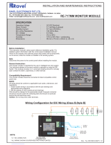
Standard AS4428.5. The board layout and picture are shown in Figure 11

OWS Standalone Manual
MA380 - Rev. 2.4
18
PCB181 R1 SUB760
FUSE0VBAT+
0V Vout 0V Vin
SF
COMA/I
+
654321
FAULT
SUPPLY
FAULT O.C.
SUPPLY
FAIL
POWER
INHIBITED
AUTOTEST
MAINS ON
ISOLATE
AMBERGREENREDREDREDGREEN
P1
P2
GREEN
S/No
MO
AUTOTEST BATTERY
RUNNING
RP3
RP4
C3
C2
ZD3
R3
U1
C4
D6
Q6Q2
Q1
RP1
M2
LF1
SW1
R4
R5
C5
ZD2
R1
R2
C1
ZD1
Q4 Q5
Q3
RP2
CR1
LK1D2
TP2
TP3
M1
TB2
D3
LD7LD6LD5LD4LD3LD2LD1
D4
D7 D5
RL4RL3
TH1
RL2
RL1
D1
TB4
TP1
C7
M3
TB3
TB5
U2
V+ COM NO NCO/C
NCNO
SUPPLY FAULT
POWER FAIL
BROOKS
+
-
+
-
+ -
POWER FAIL
DRY CONTACT
FOR MORE THAN 5A POWER SUPPLY
POWER SUPPLY FAULT
DRY CONTACT
EXTERNAL TEST
INHIBIT
28.2V DC IN
TO POWER ON LED
27. 5V DC OUT
MONITORED
TO BATTERIES
TO EXTERNAL CIRCUIT BREAKER
PIC 16F88 I/P
TO POWER SUPPLY FAULT LED
or WATCHDOG PULSE OUTPUT
Figure 11 SUB760 Power Supply Monitoring Board
The power supply supervision module continuously monitors the battery charger and batteries to detect
any of the following fault conditions:
Loss of Mains power source,
Loss of standby power source (batteries),
Charger output voltage higher than 28.2V or lower than 26.5V,
Battery capacity low i.e. battery voltage less than 23.8V
Auto battery test fail,
Total loss of the dual power sources, battery voltage less than 21V.
SUB760 provides an automatic battery test facility every approximately 70 hours. During the test, the
DC supply input is disconnected and the system operates on batteries only for approximately 30 minutes
at normal quiescent condition. If the auto battery test failed, the power supply fault LED latches and the
test will be terminated, to reset the latched LED, press switch SW1.
An automatic battery test inhibit input is available to terminate the auto battery test, if required. A typical
application for the battery test inhibit switch is the alarm condition. An alarm N/O contact can be
connected to the input to inhibit the auto battery test in alarm condition, this is normally used when the
OWS is fitted inside the CIE.
The on-board jumper link LK1 is set as shown in Table 10. Due to different requirements in both
AS4428.5 and NZS4512, LK1.3 must be fitted when the power supply supervision module is to be used
in any system for the New Zealand market.
Table 10 Power Supply Supervision Jumper Link Setting
Jumper Function Position Selection
LK1.1 Mode of Operation
IN
Test Mode (factory only)
OUT
Normal Mode (default)
LK1.2
Not Installed
LK1.3 Mode of Operation
IN
New Zealand
OUT
Australia (default)
LK1.4
Not Installed
LK1.5 Charger Fault Tolerance
IN
3%
OUT
2% (default)
LK1.6
Not used

OWS Standalone Manual
MA380 - Rev. 2.4
19
3.6.2 Connections
Table 11 Connections of the Power Supply Supervision Module
Designator Type No. Label Pin Description
TB2
Screw
terminals
1
Vout
27.5 V DC +/- 2% to provide power to OWS
2 0V
TB3
Screw
terminals
1
BAT+
Connect to the batteries.
2 0V
3
FUSE
Parallel to the built-in 7A circuit breaker.
Connect to an additional circuit breaker when the
current exceeds 7A.
4
TB5
Screw
terminals
1 ON Power ON indicator.
2 Vin
DC power input, Connect to DC output of the AC/DC
power supply, set to 28.2V +/- 2%.
3 0V
TB4
Screw
terminals
1
V+
External automatic battery test inhibit input. Disable
the automatic battery test when two pins are shorted.
2 A/I
3
Supply
Fault
COM
PSU fault changeover relay contact, 5A @ 30V.
Normally energised relay
4 NO
5 NC
6 S/F O/C
Transistor open collector PSU fault output.
Connected to display board SUB925 to provide
Power ON indication.
7
Power
Fail
COM
PSU Power fail changeover relay contact, 5A @ 30V.
Normally energised relay
8 NO
9 NC
3.6.3 On-Board LED indications
Table 12 LED Indicators on the Power Supply Supervision Board
Designator Label Colour Active conditions
Normal
Condition
LD1 MAINS ON Green Mains power input is normal. On
LD2
AUTOTEST
RUNNING
Red Automatic battery test is running. OFF
LD3
BATTERY
ISOLATE
Red Batteries have been disconnected from the system. OFF
LD4
AUTOTEST
INHIBITED
Red Automatic battery test is inhibited. Off
LD5 POWER FAIL Green System is not in Power Fail conditions. On
LD6
SUPPLY FAULT
O.C.
Yellow
One or more power supply faults have been
detected.
Off
LD7 SUPPLY FAULT Green No power supply fault has been detected. On
3.6.4 Battery Calculations
Brooks BOWS020W, BOWS060W and BOWS120W are fitted with 150 Watt switch mode power supply
(BOWS020W can be fitted with 70W or 50W), batteries may vary. The battery capacity is determined by
the following:
Standby time, the system in quiescent condition and running on batteries only.
/