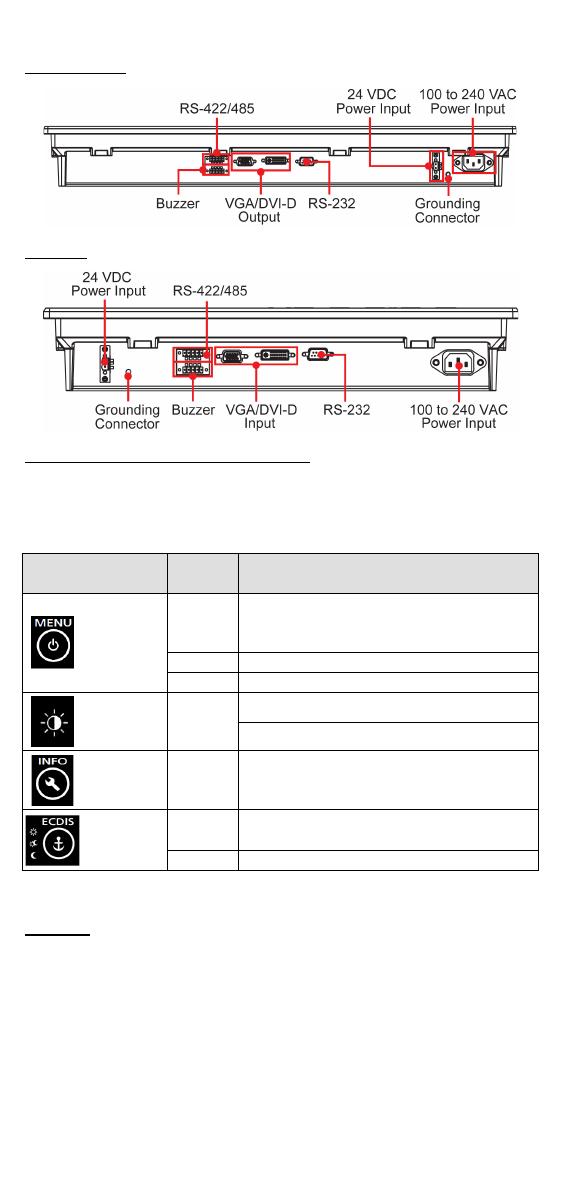
Moxa Technologies MD-200 Series Quick Install Guide

Type
Quick Install Guide

This manual is also suitable for

P/N: 1802002260012
*1802002260012*
MD-200 Series
Quick Installation Guide
Version 2.1, January 2021
Technical Support Contact Information
www.moxa.com/support
2021 Moxa Inc. All rights reserved.
- 2 -
Overview
The MD-200 marine display series is designed for durably reliable service
as an ECDIS display component. The MD-200 series offers full range
dimming and optional optical bonding, making it well-suited not only for
ECDIS applications, but also for a variety of other bridge applications.
The MD-200 series features both AC and DC power inputs, and can be
conveniently installed on any bridge, without the need for extra
hardware.
Moxa’s marine displays are compliant with the most important industrial
marine standards, including IEC 60945, DNV, and IACS-E10, giving
strong assurance of their suitability for marine applications.
The following lists the models in the MD-200 series:
MD-226X: 26-inch display with 16:10 aspect ratio.
MD-224X/MD-224Z: 24-inch display with 16:9 aspect ratio.
MD-219X/MD-219Z: 19-inch display with 5:4 aspect ratio.
Package Checklist
Before installing the MD-200 series, verify that the package contains the
following items:
MD-200 series display
VGA cable
DVI-D cable
2-pin terminal block x 1
5-pin terminal block x 2
Quick installation guide (printed)
Warranty card
NOTE: Please notify your sales representative if any of the above items
are missing or damaged.
Hardware Installation
Appearance
- 3 -
MD-226/224
MD-219
SavvyTouch Display Control Buttons
The following table describes the SavvyTouch display controls on the
front surface of the MD-200 series. These intelligent controls will light up
with a simple wave of your hand over the area of the screen where they
are located.
Name
Display
Color
Control Function/Color Legend
Menu/
Power
Green
Display is powered on and functioning
normally. Touch the button to show the
OSD settings menu
Red
No input signal detected. Display standby
Off
Power is down and the display is off
Brightness
White
+: To increase brightness of panel
-: To decrease brightness of panel
Info
Off AC/DC power is functioning normally
Display
mode
White
Switch between DAY/DUSK/NIGHT
brightness modes
Off
Panel brightness out of default range
Installing the MD-200 Series
Desktop
The MD-200 series comes with optional brackets that allow you to install
the display on a horizontal surface, such as a desktop. Three round
screws are required for each bracket. See the figure for detailed screw
specifications and their torque values.
Place your MD-200 series display on a clean, flat, well-ventilated desktop.
To protect the computer from overheating, leave some ventilation space
between the MD-200 series and other equipment.
Do NOT place equipment or objects on the panel, as this might damage
internal components.
- 4 -
Panel Mounting
The MD-200 series comes with 14 optional clamp mounts for installation
on a wall (where space has been cut out to accommodate the rest of the
hardware) or into computing stations where a flush mount is desired.
The maximum thickness of the surface to which the computer can
be clamped is 11 mm. For a secure mounting, all 14 clamps must be
used.
The clamp arms are fastened into slots on all four sides of the MD-200
series. Use the short M4 SUS screws to fasten the clamp arms to the
MD-200 series mounting slots, as shown in the following magnified inset
in the diagram. Next, use the clamps to fasten the MD-200 series to its
mounting point; please note the torque value as shown in the figure.
- 5 -
VESA Mounting
The MD-200 series also comes with an optional VESA mounting kit. Six
flat screws and four round screws are required to fasten the VESA
mounting bracket. See the following figure for detailed screw
specifications and torque values.
An additional four screws (not included in the kit) are required to mount
the display on a VESA rack. For this purpose, use M6 screws that are
between 10 and 12 mm in length.
Connector Description
Extending the Display
The MD-200 series comes with both standard VGA and DVI-D interfaces
on the bottom panel. It automatically detects whether the input video
source is from the VGA or DVI-D interface.
Configuring the Display via the Serial Port
The MD-200 series has two serial ports. The RS-232 port uses a DB9
connector, and the RS-422/485 port uses a terminal block connector.
Either serial port can be used to modify the display parameters using
UART commands. For information on serial port configuration, see the
MD-200 Series Hardware Manual.
The pin assignments for the ports are shown in the following table:
Pin
RS-232
1
DCD
2
RxD
3
TxD
4
DTR
5
GND
6
DSR
7
RTS
8
CTS
RS-422/485 (Terminal Block) Pinouts
Pin
RS-422
RS-485
(4-wire)
RS-485
(2-wire)
1
RxDB(+)
RxDB(+)
2
RxDA(-)
RxDA(-)
3
TxDB(+)
TxDB(+)
DataB(+)
4
TxDA(-)
TxDA(-)
DataA(-)
5
GND
GND
GND
- 6 -
Powering on/off the MD-200 Series
To power on the MD-200 series, connect the unit to an AC power source,
a DC power source, or both. Touch the MENU button for 1 second to turn
on the display. Touch the MENU button for 4 seconds to turn off the
display.
Grounding the MD-200 Series
Proper grounding and wire routing help to limit the effects of noise from
electromagnetic interference (EMI). Run the ground connection from the
ground screw to the grounding surface prior to connecting the power
source.
For detailed configuration of the MD-200 Series, refer to the MD-200
Series Hardware Manual.
  • Page 1 1
  • Page 2 2
  • Page 3 3
  • Page 4 4
  • Page 5 5
  • Page 6 6

Moxa Technologies MD-200 Series Quick Install Guide

Type
Quick Install Guide
This manual is also suitable for

Ask a question and I''ll find the answer in the document

Finding information in a document is now easier with AI