senva TotalSense Series User manual

Type
User manual

senva TotalSense Series is a customizable indoor air quality sensor that allows you to monitor various environmental parameters such as carbon dioxide (CO2), relative humidity (RH), temperature, total volatile organic compounds (TVOC), particulate matter (PM), and ambient light. It features programmable set-point relays, allowing you to control ventilation or other equipment based on sensor readings. You can choose analog or communications output types, with communications versions offering Modbus RTU or BACnet MS/TP connectivity.

senva TotalSense Series is a customizable indoor air quality sensor that allows you to monitor various environmental parameters such as carbon dioxide (CO2), relative humidity (RH), temperature, total volatile organic compounds (TVOC), particulate matter (PM), and ambient light. It features programmable set-point relays, allowing you to control ventilation or other equipment based on sensor readings. You can choose analog or communications output types, with communications versions offering Modbus RTU or BACnet MS/TP connectivity.

INSTALLATION INSTRUCTIONS
senvainc.com 1-866-660-8864 (F)1-503-296-2529 9290 SW Nimbus Ave. Beaverton Oregon 97008
Indoor Air Quality Sensor
BACnet/Modbus/Analog
PRODUCT IDENTIFICATION
AQ2 -
VOC
CO2
Pkg RHOut
Package
W = Surface
Output Type
A = 3-wire Analog
B = BACnet/Modbus
Temperature Output
A = None
B = Transmitter and display/comms temp reading
C = 100Pt RTD
D = 1000Pt RTD
E = 10K Type 2
F = 10K Type 3
G = 10k w/11k
H = 3k
I = 2k2
J = 1k8
K = 20k
CO2
A = None
C = Standard CO
D = Dual Channel CO
Relative Humidity
A = None
2 = 2% RH accuracy
PM
VOC
A = None
V = TVOC
Particulate Matter
A = None
P = PM 1.0, 2.5, 4.0, 10.0 (Available on AQ2W-B
BACnet/Modbus versions only)
Display
X = None
D = Color OLED Display
S = Color OLED display with solid cover
R = Air Quality Ring
TDisp
PIR Motion/Occupancy Sensor
Blank = None
P = PIR Sensing
IMPORTANT WARNINGS
Only qualied trade installers should install this product
This product is not intended for life-safety applications
Do not install in hazardous or classied locations
The installer is responsible for all applicable codes
De-energize power supply prior to installation or service
PRODUCT APPLICATION LIMITATION:
Senva products are not designed for life or safety applications. Senva products
are not intended for use in critical applications such as nuclear facilities, human
implantable device or life support. Senva is not liable, in whole or in part, for
any claims or damages arising from such uses.
FEATURES
The TotalSense series design allows customization for a sensor
that meets project requirements for monitoring temperature,
carbon dioxide (CO), total volatile organic compounds
(TVOC), particulate matter (PM), relative humidity (RH),
passive-infrared occupancy sensor (PIR), and ambient light.
The product can be ordered as a stand-alone CO, RH, Temp,
TVOC, PM, or PIR sensor as well as almost any combination of
sensors. Resistive-set-point sliders and pushbuttons are also
available to meet the requirements for any job. All models
come standard with programmable set-point relay (except on
PM models) and barometric pressure compensation for CO.
Choose the analog version to receive up to three
selectable and programmable analog outputs or utilize the
communications version to access a myriad of data through
Modbus RTU or BACnet MS/TP. Communications version
comes standard with ambient light sensing.
To verify the features see the
'Product Identication section of
the installation manual or use the
conguration tool at senvainc.com or
scan the QR code on the right. TotalSense Congurator
Accessories † ‡
C = 1k  Setpoint Slider
D = 10k  Setpoint Slider
T = 200-900  Setpoint Slider
E = 910  oset resistor (available with slider only)
S= Slider override Pushbutton (available with slider only)
O = Thermistor Override Pushbutton
U = User Pushbutton
Additional Setpoint sliders and oset resistors available
upon request
‡ Slider and pushbutton options not available with PM sensor
Acc
T talSenseTM Series T talSenseTM Series
T tal TM Series
COMPUTER
ROOM
OUTSIDE
WALL OR WINDOW
TOO HOT/COLD
INSIDE WALL
TOO HOT/COLD
COPIER
TOO NEAR
EQUIPMENT OR DOORWAY
GOOD
LOCATION
GOOD
LOCATION
GOOD
LOCATION
INSTALLATION
1. IMPORTANT! Locate the device in an area away from
ventilation sources and heat generating equipment and
appliances. The device should be mounted at light switch
height in a vertical orientation. Use insulating material behind
the device to ensure reading accuracy.
NOTE: Do not install the device in multi-gang electrical boxes
with line voltage or other electrical devices.
2. Wire according to application. See “Setup- Wiring” section for
details.
3. Install backplate to wall or junction-box using screws
provided. If using optional trim ring, click the TotalSense into
it and secure using 1 screw. Then, mount it to wall or junction
box.
4. Apply power.
5. To congure communications or analog voltage scaling,
congure DIP switches according to “Setup - Analog” or "setup -
Communications" sections.
To congure the device using the color OLED screen, reference
the “Setup - Display section.
SETUP - WIRING
The following diagrams show terminal locations for each
version of the TotalSense. The number of options selected will
determine which of the terminals are included on each device.
For example, if only one sensor is chosen, only 1 pair of analog
terminals will be present. Each device will have 4-8 terminals
on the left side, 0-4 on the top, and 0-4 on the right side.
Analog Wiring
*These terminals may not be populated depending on which
model is ordered.
Communications Wiring
NOTE: A 120  termination resistance may be added in parallel
with the RS-485 +/- by moving the very top DIP switch (DIP 1)
to the left position. See “DIP Conguration section for more
information.
SETUP - ANALOG
Switch 1 with two DIP switches will be provided with every
device and Switch 2 with an additional 12 DIP switches will be
provided with communications devices. The following diagram
shows how each setting can be congured using the provided
switches.
For analog voltage output, select either 0-5V (left) or 0-10V
(right) outputs. These analog ranges can be adjusted using
the color OLED display. Adjustments made using the OLED
display will override this DIP switch setting.
DIP
1
2
Left
0-5V
N/A
Right
0-10V
N/A
DIP
1
2
Left
N/A
Modbus
Right
Termination Resistor
BACnet
Comms DIP Settings
Analog DIP Settings
Left
0 (o)
0
0
0
0
0
0
0
0
0
0
0
DIP
1
2
3
4
5
6
7
8
9
10
11
12
Function
MAC6
MAC5
MAC4
MAC3
MAC2
MAC1
MAC0
BAUD2
BAUD1
BAUD0
D/P/S1
D/P/S0
Right
1 (on)
1
1
1
1
1
1
1
1
1
1
1
DIP
1-7
8-10
11-12
Function
MAC Address/
Modbus Address
0-127 (binary)
Baud Rate
0(000)=9600
1(001)=19200
2(010)=38400
3(011)=57600
4(100)=76800
5(101)=115200
Data/Parity/Stp
0(00)=8N1
1(01)=8N2
2(10)=8O1
3(11)=8E1
S1
S1
S3
ON
ON
ON
1 2 1 2 3 4 5 6 7 8 9 10 11 12
PWR
02 O1
GND
O3
Analog Terminals
*BUTTON *SLIDER
S1
S3
Comms Terminals
*BUTTON *SLIDER
S1
PWR
02 O1
GND
O6 O5 O4 O3
S3
S1
S1
*RELAY *THERMISTOR
RELAY* THERMISTOR*
BUTTON* SLIDER*
PWR
O1O2 O2
GND
O6 O5 O4 O3
RELAY* THERMISTOR*
BUTTON* SLIDER*
PWR
O1
GND
O3
PWR
02 O1
GND
O3
Analog Terminals
*BUTTON *SLIDER
S1
S3
Comms Terminals
*BUTTON *SLIDER
S1
PWR
02 O1
GND
O6 O5 O4 O3
S3
S1
S1
*RELAY *THERMISTOR
RELAY* THERMISTOR*
BUTTON* SLIDER*
PWR
O1O2 O2
GND
O6 O5 O4 O3
RELAY* THERMISTOR*
BUTTON* SLIDER*
PWR
O1
GND
O3
PWR
02 O1 GND
O3
Analog Terminals
*BUTTON *SLIDER
S1
S3
Comms Terminals
*BUTTON *SLIDER
S1
PWR
02 O1 GND
O6 O5 O4 O3
S3
S1
S1
*RELAY *THERMISTOR
RELAY* THERMISTOR*
BUTTON* SLIDER*
PWR
O1O2 O2
GND
O6 O5 O4 O3
RELAY* THERMISTOR*
BUTTON* SLIDER*
PWR
O1 GND
O3
PWR
02 O1 GND
O3
Analog Terminals
*BUTTON *SLIDER
S1
S3
Comms Terminals
*BUTTON *SLIDER
S1
PWR
02 O1 GND
O6 O5 O4 O3
S3
S1
S1
*RELAY *THERMISTOR
RELAY* THERMISTOR*
BUTTON* SLIDER*
PWR
O1O2 O2
GND
O6 O5 O4 O3
RELAY* THERMISTOR*
BUTTON* SLIDER*
PWR
O1 GND
O3
PWR
02 O1 GND
O3
Analog Terminals
*BUTTON *SLIDER
S1
S3
Comms Terminals
*BUTTON *SLIDER
S1
PWR
02 O1 GND
O6 O5 O4 O3
S3
S1
S1
*RELAY *THERMISTOR
RELAY* THERMISTOR*
BUTTON* SLIDER*
PWR
O1O2 O2
GND
O6 O5 O4 O3
RELAY* THERMISTOR*
BUTTON* SLIDER*
PWR
O1 GND
O3
Page 2 of 6
DIMENSIONS
A concealment ring is provided to
hide oversized cutouts or to mount
using a European sized junction box.
6.35
[161.3]
3.69
[93.7]
3.00
[76.2]
1.07
[27.1]
1.25
[31.6]
0.229
[35.8]
5.66
[143.8]
SETUP - COMMUNICATIONS
DIP
1
2
Left
0-5V
N/A
Right
0-10V
N/A
DIP
1
2
Left
N/A
Modbus
Right
Termination Resistor
BACnet
Comms DIP Settings
Analog DIP Settings
Left
0 (o)
0
0
0
0
0
0
0
0
0
0
0
DIP
1
2
3
4
5
6
7
8
9
10
11
12
Function
MAC6
MAC5
MAC4
MAC3
MAC2
MAC1
MAC0
BAUD2
BAUD1
BAUD0
D/P/S1
D/P/S0
Right
1 (on)
1
1
1
1
1
1
1
1
1
1
1
DIP
1-7
8-10
11-12
Function
MAC Address/
Modbus Address
0-127 (binary)
Baud Rate
0(000)=9600
1(001)=19200
2(010)=38400
3(011)=57600
4(100)=76800
5(101)=115200
Data/Parity/Stp
0(00)=8N1
1(01)=8N2
2(10)=8O1
3(11)=8E1
S1
S1
S3
ON
ON
ON
1 2 1 2 3 4 5 6 7 8 9 10 11 12
DIP switches 1-7 can be arranged in 127 binary congurations
to set the MAC address (BACnet) or the Modbus address.
Similarly, the baud rate can be set by DIP switches 8-10 and the
data/parity/stop bit can be set by DIP switches 11 and 12.
ADVANCED SETUP
Display Navigation
Guide
BACnet Protocol
Guide
PWR
02 O1 GND
O3
*BUTTON *SLIDER
S1
S3
S3
S1
SETUP - DISPLAY
Example screen:
TotalSense devices ordered with color OLED display can
be congured from the display or over communications (if
applicable). The default screen layout will vary depending
on which model is ordered. Each of the 5 sections can
be customized. See “Display Navigation Guide for more
information.
Set Point
oF
72
oF
72
%RH
45
Good
Air Quality
Centern/O
Noner Quality
Upper
Relayint
Upper
Slider
Display
Center
None
Temp
RH
CO2
Centern/O
Noner Quality
Upper
Relayint
Upper
Slider
RH
Range Max
Min 0
199 %
Max 100
Centern/O
Noner Quality
Upper
Relayint
Upper
Slider
RH
Range Max
Min 0
099 %
Max 100
Centern/O
Noner Quality
Upper
Relayint
Upper
Slider
RH
Range Max
Min 0
109 %
Max 100
Centern/O
Noner Quality
Upper
Relayint
Upper
Slider
RH
Range Max
Min 0
2000 PPM
Max 100
Go Back
Display
Analog Output 1
Analog Output 2
Analog Output 3
Settings
Go Back
Center Display
None
Upper Left
Relay State
Display
Go Back
Protocol
Modbus RTU
Baud
115200
View Comms
Go Back
CO2
887 PPM
Barometric Pressure
29.92 in/Hg
View Readings
Centern/O
Noner Quality
Upper
Relayint
Upper
Slider
Display
Center
Air Quality
TVOC PPB
TVOC ug/m3
PM
Go Back
Center Display
Air Quality
Upper Left
Relay State
Display
Lorem ipsum
425
PPM
x 4
Home
Settings
View Comms
View Readings
Administration
Main Menu
Fair
Air Quality
Screen saver
(locked)
oF
%RH
45 72
Fair
Air Quality
Home Screen
(unlocked)
5 seconds
V
V
To unlock To settings
V
V
V
VV V
Home
Settings
View Comms
View Readings
Administration
Main Menu
Home
Settings
View Comms
View Readings
Administration
Main Menu
Scroll
V
Scroll
Save
Save
Digit
Save
Digit
Save
Digit
Save
Entry
Screen Lock:
If the screen is locked, a lock icon will show when any button
is pressed. To unlock, hold the UP and DOWN arrows for 5
seconds. To disable the lock feature, see “Display Navigation
Guide”.
Set Point
oF
72
oF
72
%RH
45
Good
Air Quality
Centern/O
Noner Quality
Upper
Relayint
Upper
Slider
Display
Center
None
Temp
RH
CO2
Centern/O
Noner Quality
Upper
Relayint
Upper
Slider
RH
Range Max
Min 0
199 %
Max 100
Centern/O
Noner Quality
Upper
Relayint
Upper
Slider
RH
Range Max
Min 0
099 %
Max 100
Centern/O
Noner Quality
Upper
Relayint
Upper
Slider
RH
Range Max
Min 0
109 %
Max 100
Centern/O
Noner Quality
Upper
Relayint
Upper
Slider
RH
Range Max
Min 0
2000 PPM
Max 100
Go Back
Display
Analog Output 1
Analog Output 2
Analog Output 3
Settings
Go Back
Center Display
None
Upper Left
Relay State
Display
Go Back
Protocol
Modbus RTU
Baud
115200
View Comms
Go Back
CO2
887 PPM
Barometric Pressure
29.92 in/Hg
View Readings
Centern/O
Noner Quality
Upper
Relayint
Upper
Slider
Display
Center
Air Quality
TVOC PPB
TVOC ug/m3
PM
Go Back
Center Display
Air Quality
Upper Left
Relay State
Display
Lorem ipsum
425
PPM
x 4
Home
Settings
View Comms
View Readings
Administration
Main Menu
Fair
Air Quality
Screen saver
(locked)
oF
%RH
45 72
Fair
Air Quality
Home Screen
(unlocked)
5 seconds
V
V
To unlock To settings
V
V
V
VV V
Home
Settings
View Comms
View Readings
Administration
Main Menu
Home
Settings
View Comms
View Readings
Administration
Main Menu
Scroll
V
Scroll
Save
Save
Digit
Save
Digit
Save
Digit
Save
Entry
Changing Settings:
To change any setting, press ENTER to see the setup menu and
navigate to the desired parameter type and press ENTER again
to choose. The example below shows how to adjust the center
reading on the display. The dashed blue line shows the desired
selections and the blue buttons show how to navigate.
Changing a value:
To adjust a numerical setting, set each digit individually and
press ENTER to move the cursor from left to right. When all
digits are set, the value will be saved when ENTER is pressed
again.
Set Point
oF
72
oF
72
%RH
45
Good
Air Quality
Centern/O
Noner Quality
Upper
Relayint
Upper
Slider
Display
Center
None
Temp
RH
CO2
Centern/O
Noner Quality
Upper
Relayint
Upper
Slider
RH
Range Max
Min 0
199 %
Max 100
Centern/O
Noner Quality
Upper
Relayint
Upper
Slider
RH
Range Max
Min 0
099 %
Max 100
Centern/O
Noner Quality
Upper
Relayint
Upper
Slider
RH
Range Max
Min 0
109 %
Max 100
Centern/O
Noner Quality
Upper
Relayint
Upper
Slider
RH
Range Max
Min 0
2000 PPM
Max 100
Go Back
Display
Analog Output 1
Analog Output 2
Analog Output 3
Settings
Go Back
Center Display
None
Upper Left
Relay State
Display
Go Back
Protocol
Modbus RTU
Baud
115200
View Comms
Go Back
CO2
887 PPM
Barometric Pressure
29.92 in/Hg
View Readings
Centern/O
Noner Quality
Upper
Relayint
Upper
Slider
Display
Center
Air Quality
TVOC PPB
TVOC ug/m3
PM
Go Back
Center Display
Air Quality
Upper Left
Relay State
Display
Lorem ipsum
425
PPM
x 4
Home
Settings
View Comms
View Readings
Administration
Main Menu
Fair
Air Quality
Screen saver
(locked)
oF
%RH
45 72
Fair
Air Quality
Home Screen
(unlocked)
5 seconds
V
V
To unlock To settings
V
V
V
VV V
Home
Settings
View Comms
View Readings
Administration
Main Menu
Home
Settings
View Comms
View Readings
Administration
Main Menu
Scroll
V
Scroll
Save
Save
Digit
Save
Digit
Save
Digit
Save
Entry
Modbus Protocol
Guide
Page 3 of 6
Set Point
oF
72
oF
72
%RH
45
Good
Air Quality
Centern/O
Noner Quality
Upper
Relayint
Upper
Slider
Display
Center
None
Temp
RH
CO2
Centern/O
Noner Quality
Upper
Relayint
Upper
Slider
RH
Range Max
Min 0
199 %
Max 100
Centern/O
Noner Quality
Upper
Relayint
Upper
Slider
RH
Range Max
Min 0
099 %
Max 100
Centern/O
Noner Quality
Upper
Relayint
Upper
Slider
RH
Range Max
Min 0
109 %
Max 100
Centern/O
Noner Quality
Upper
Relayint
Upper
Slider
RH
Range Max
Min 0
2000 PPM
Max 100
Go Back
Display
Analog Output 1
Analog Output 2
Analog Output 3
Settings
Go Back
Center Display
None
Upper Left
Relay State
Display
Go Back
Protocol
Modbus RTU
Baud
115200
View Comms
Go Back
CO2
887 PPM
Barometric Pressure
29.92 in/Hg
View Readings
Centern/O
Noner Quality
Upper
Relayint
Upper
Slider
Display
Center
Air Quality
TVOC PPB
TVOC ug/m3
PM
Go Back
Center Display
Air Quality
Upper Left
Relay State
Display
Lorem ipsum
425
PPM
x 4
Home
Settings
View Comms
View Readings
Administration
Main Menu
Fair
Air Quality
Screen saver
(locked)
oF
%RH
45 72
Fair
Air Quality
Home Screen
(unlocked)
5 seconds
V
V
To unlock To settings
V
V
V
VV V
Home
Settings
View Comms
View Readings
Administration
Main Menu
Home
Settings
View Comms
View Readings
Administration
Main Menu
Scroll
V
Scroll
Save
Save
Digit
Save
Digit
Save
Digit
Save
Entry
FEATURE - AIR QUALITY
If Air Quality is selected to be displayed or if the Air quality Ring
option is selected, the device will monitor each CO, VOC, PM,
RH, and Temp sensor present and will display accordingly.
The average air quality is calculated as follows:
1.Each sensor's current reading is rated according to the below
thresholds and given an air quality index (AQI). For each sensor,
a good rating is given an AQI of 90, fair is given an AQI of 60
and poor is given an AQI of 0.
2.The average air quality is calculated and a total air quality
rating is assigned based on the following thresholds. These
thresholds can be adjusted using communications or in the "Air
Quality Settings" menu from the display.
a. Good ≥ 75
b. 55 < Fair < 75
c. Poor ≤ 55
GOOD (AQI 90) FAIR (AQI 60) POOR (AQI 0)
PM2.5 <35 ug/m 35-55 ug/m >55ug/m
TVOC <1000 ug/m 1000-3000 ug/m >3000 ug/m
CO2 <1200 PPM 1200-2000 PPM >2000 PPM
Temp 64-79oF <64oF, >79oF
RH 30-60% <30%, >60% <10%, >90%
FEATURE - PIR OCCUPANCY
If PIR option is selected, the PIR (Passive Infrared) sensor will
trigger anytime it detects motion. If used to activate the
relay or as a communications data point, an o-delay can be
programmed using the display or through communications.
The below shows the distance at which the sensor will trigger
a motion event based on its adjustable sensitivity rating. A
motion event, for the purpose of this graph, is considered the
movement of a person or large object.
Side view (Y plane/vertical)
Top view (X plane/horizontal)
15ft (4.5m)
5ft (1.5m)
20ft (6m)
Sensitivity = 80 (default)
Sensitivity = 0
Sensitivity = 100
160º20º
135º45º
15ft (4.5m)
5ft (1.5m)
38º
38º
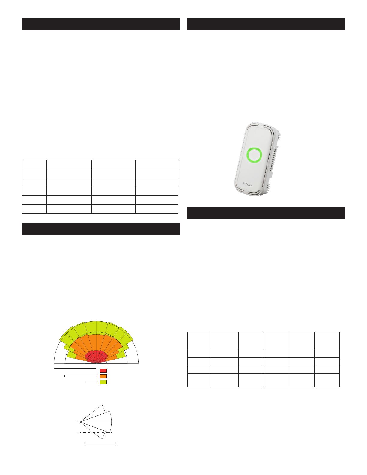
FEATURE - AIR QUALITY RING
An Air Quality (AQ) Ring may be selected in place of a display.
The AQ ring will glow green, yellow, or red according to the
detected levels of CO, PM, VOC, RH, and Temp. See “Feature -
Air Quality section for thresholds.
The AQ Ring may be disabled or brightness may be adjusted if
the communications model is selected. Additionally, it may be
set to only display yellow or red when air quality has degraded
to fair or poor levels. See TotalSense “BACnet/Modbus User
Guide” for more information.
AQ Ring will turn on and o at a 5 second interval if a sensing
error occurs. See "Troubleshooting" section for information.
FEATURE - SETPOINT RELAY
All TotalSense models come standard with a setpoint relay
except those ordered with a PM sensor.
The relay source determines which reading or status will
activate the relay. This can be set or adjusted using the display
or communications. See 'Display Navigation Guide' or the
applicable protocol guide for details.
Each source selection has a range listed below. To set turn-
on and turn-o thresholds, a percentage of this range can
be entered into each corresponding parameter. On display
versions, the calculated value will show as the percentage is
adjusted.
Each time a new source is selected, a default relay threshold
will be set based on which technology is chosen. These auto-
set values are listed in the table below.
Source
Selection
Range Default
Turn-on
Threshold
Calculated
Turn-on
value
Default
Turn-o
Threshold
Calculated
Turn-o
value
CO2 0-10,000 PPM 8.0% 800 PPM 7.0% 700 PPM
RH 0-100% RH 60% 60% RH 55% 55% RH
Temp* -40 - 122 oF 74% 80oF 73% 78oF
TVOC 0-10000 g/
m
4% 400 g/m 3.5% 350 g/m
*To calculate threshold % for a given temperature, use the
following equation:
% Threshold = (T+40)/162*100
Where T is the temperature in oF
Page 4 of 6
TROUBLESHOOTING
Symptom Solution
The device has experienced an error with one of
the sensors. Navigate to Advanced Settings >
"Diagnostics" screen to view more information.
All zeros will be displayed if no error is
present. See "Display Navigation Guide", or the
applicable communications guide or consult
factory for troubleshooting help or replacement
element.
No output Check wiring. Ensure power supply meets
requirements.
Reading
error
Verify control panel software is congured for
correct output scaling.
Verify accuracy of test instrument. Observe
installation and calibration guidelines.
Verify unit is located away from sources of hot/
cold.
Verify sensing element is inserted properly.
Perform calibration only if necessary.
SENVA TECHNICAL SUPPORT
Need further assistance? Call our toll-free number for live
technical support: (866) 660-8864 or feel free to email us at
CO CALIBRATION
Automatic Calibration feature:
The CO sensor will automatically baseline CO levels and
gradually make adjustments to compensate for sensor drift due
to long-term aging of the IR light source. In applications where
CO levels are continuously elevated, or spaces are occupied
day and night, it is recommended to use our dual channel CO
sensor with automatic calibration disabled.
Senva CO sensors are factory calibrated to controlled test
gases. No eld calibration is necessary or recommended.
However, to facilitate compliance with job requirements and
commissioning procedures, provisions for eld calibration are
provided:
1. Locate calibration instrument and sensor in close proximity
to each other in a controlled environment free of drafts,
people, and equipment to reduce inuence on CO and
temperature.
2. Compare output of sensor to calibration instrument, and
note dierence. (In 0-10V mode/2000ppm range, 1V =200ppm)
3. Refer to the "Setup-Display" section to adjust oset value
for CO as needed. Factory calibration may be restored by
setting oset back to 0.
In extreme cases where the sensor module has been damaged,
a new module may be installed in the eld. Consult factory for
replacement module and instructions.
Alarm Icon
on home
screen or
blinking AQ
Ring
TVOC OPERATION
Training Mode
The TVOC sensor has articial intelligence (AI) that allows it to
sense and understand dierent environments. This AI may take
up to 7 days to acclimate to an environment once installed. For
this reason, a TVOC reading is not included in the Air Quality
calculation until it has been powered for 7 days.
During this time, the sensor will go into "training mode"
and will not display or output a TVOC value. Instead, the
display will show "Training days" where "X" is how many
days the device has been in training mode and 7 days is the
expected duration. Once it reaches 7 days, a reading will be
shown. Using communications, the TVOC reading will show a
countdown from -7 to 0 days; once it hits zero the device will
switch into normal operation.
Device shown is in TVOC training mode.
Manual Calibration
No manual eld calibration is necessary. To maintain accuracy,
the TVOC sensor will be required to be exposed to fresh air
at least once every 10 days. This can be accomplished by
increasing airow in an area or by opening a window.
Scaling:
Senvas TVOC sensor uses an Ethanol reading to determine a
raw TVOC value. Additionally, conversion from µg/m uses the
molecular weight of Ethanol. To scale based on a dierent gas
baseline, user may enter a scaling factor in TVOC Settings on
the display or using communications.
oF
72
TVOC
Training
%RH
45
Good
Air Quality
Page 5 of 6
SPECIFICATIONS
Power Supply Without Display
With LED Ring or Display
16-30VDC/24VAC(1), 3.5W nominal, 4W max.
24-30 VDC/24VAC(1), 4.3W nominal, 5W max
Interface Color OLED (optional) 1.5” Organic LED Display, 128x128 PX, color
Air Quality Ring Color changing (red/yellow/green) LED ring
Analog Outputs (Analog
version only)
Quantity Up to 3 outputs
Source CO, RH%, Temp, Temp slider, TVOC (selectable)
Scale 0-5V, 0-10V, 4-20mA (switch selectable, programmable per output)
Protocol Output
(Communications version
only)
Protocol BACnet MS/TP or Modbus RTU
Connection 3-wire RS-485, with isolated ground
Data Rate 9600, 19200, 38400, 57600, 76800, 115200 (switch selectable)
Address Range 0-127
Relay Set-point (standard
except for PM models)
Type Solid-state output, 1A @ 30VAC/DC, N.O.
Source CO setpoint, RH setpoint, Temp setpoint, TVOC setpoint, PIR motion, air
quality, o (selectable)
Polarity NO/NC (selectable)
CO (optional)
Type Non-dispersive Infrared (NDIR)
Accuracy
±(30ppm + 3% of reading) (400-2000ppm), -10-50ºC, 0-85%RH
±(50ppm+ 5% of reading) (2000-5000ppm), -10-50ºC, 0-85%RH
>5000ppm consult factory
Resolution 1 ppm
Range 0-2000 PPM (Default) (Programmable up to 10,000 PPM)
Response time 90 seconds to 90% reading
Sample rate 1s
Temp and Pressure Compensated. Barometric pressure also readable over communications
Relative Humidity
(optional)
Type Digital CMOS
Accuracy ±2% over 0 to 80%RH range
Resolution 0.05%RH
Response time (3) 30s
Sample rate 3s
Operating range 0 to 100%RH (non-condensing)
Operating conditions (4) -4 to 140F (-20 to 60° C) @ RH>90%; -4 to 176F @ RH=50%
With RH option Without RH option
Type Silicon Band-gap NTC Thermistor
Temperature Transmitter
(optional)
Nominal Accuracy ±0.3° C (operating range) ±0.5° C (operating range)
Maximum Accuracy  ±0.5° C (at 25° C), ±1.0° C ±1.0° C (at 25° C), ±2.0° C
Resolution 0.01° C 0.05° C
Response time 30s 30s
Sample rate 3s 100ms
TVOC (optional)
Type MOS
Gas Total VOC
Range 0-10,000 g/m
Response Time <10s
Temp, Pressure Compensated
Output 0-2000 g/m (default) Programmable up to 10,000 g/m
PMx (optional)
CLASS 1 LASER PRODUCT
Type Optical
Size Range PM1.0, PM2.5, PM4.0, PM10.0
Scale 0-1000 g/m
Lower detection limit 0.3 m
Precision ±10 g/m (0-100g/m); ±10% (100-1000 g/m
PIR (optional)
Type Passive Infrared
Axis X eld of view 140, 15 ft (4.5m)
Axis Y eld of view 76, 15 ft (4.5m)
Ambient Light Type Phototransistor
Scale 0-100 fc (lm/ft), readable over communications
Operating Environment Temperature 32 to 122F (0 to 50C)
Humidity 0-95% non-condensing
Enclosure Material ABS Plastic
Dimensions 5.67”h x 3.00”w x 1.07”d
Compliance Agency CE, RoHS
(1) One side of transformer, secondary is connected to signal common. Dedicated transformer is recommended.
(2) Models with PM sensor included achieve ±5% accuracy over 0 to 80%RH range and an additional temperature shift of up +0.5° C
(3) Time for reaching 63% of reading at 25° C and 1 m/s airow
(4) Long term exposures to conditions outside normal range at high humidity may temporarily oset the RH reading (+3%RH after 60 hours.)
Issued 7/28/2021 Document #152-0401-0C
  • Page 1 1
  • Page 2 2
  • Page 3 3
  • Page 4 4
  • Page 5 5
  • Page 6 6

senva TotalSense Series User manual

Type
User manual

senva TotalSense Series is a customizable indoor air quality sensor that allows you to monitor various environmental parameters such as carbon dioxide (CO2), relative humidity (RH), temperature, total volatile organic compounds (TVOC), particulate matter (PM), and ambient light. It features programmable set-point relays, allowing you to control ventilation or other equipment based on sensor readings. You can choose analog or communications output types, with communications versions offering Modbus RTU or BACnet MS/TP connectivity.

Ask a question and I''ll find the answer in the document

Finding information in a document is now easier with AI