Page is loading ...

Page 1 of 5
Specications
Size: 2.8” H x 5.8” W x 5.6” D
Input Voltage: 12-24 VDC
Temp. Range: -40ºC to 60ºC
-40ºF to 140ºF
Output Power: 150W per output (300W Total)
IMPORTANT! Read all instructions before installing and using. Installer: This manual must be delivered to the end user.
WARNING!
Failure to install or use this product according to manufacturer’s recommendations may result in property damage, serious injury, and/
or death to those you are seeking to protect!
Do not install and/or operate this safety product unless you have read and understood the safety information
contained in this manual.
1. Proper installation combined with operator training in the use, care, and maintenance of emergency warning devices are essential to
ensure the safety of emergency personnel and the public.
2. Emergency warning devices often require high electrical voltages and/or currents. Exercise caution when working with live electrical
connections.
3. This product must be properly grounded. Inadequate grounding and/or shorting of electrical connections can cause high current arcing,
which can cause personal injury and/or severe vehicle damage, including re.
4. Proper placement and installation is vital to the performance of this warning device. Install this product so that output performance of
the system is maximized and the controls are placed within convenient reach of the operator so that they can operate the system without
losing eye contact with the roadway.
5. Do not install this product or route any wires in the deployment area of an air bag. Equipment mounted or located in an air bag
deployment area may reduce the eectiveness of the air bag or become a projectile that could cause serious personal injury or death.
Refer to the vehicle owner’s manual for the air bag deployment area. It is the responsibility of the user/operator to determine a suitable
mounting location ensuring the safety of all passengers inside the vehicle particularly avoiding areas of potential head impact.
6. It is the responsibility of the vehicle operator to ensure daily that all features of this product work correctly. In use, the vehicle operator
should ensure the projection of the warning signal is not blocked by vehicle components (i.e., open trunks or compartment doors),
people, vehicles or other obstructions.
7. The use of this or any other warning device does not ensure all drivers can or will observe or react to an emergency warning signal.
Never take the right-of-way for granted. It is the vehicle operator’s responsibility to be sure they can proceed safely before entering an
intersection, drive against trac, respond at a high rate of speed, or walk on or around trac lanes.
8. This equipment is intended for use by authorized personnel only. The user is responsible for understanding and obeying all laws
regarding emergency warning devices. Therefore, the user should check all applicable city, state, and federal laws and regulations. The
manufacturer assumes no liability for any loss resulting from the use of this warning device.
Installation and Operation Instructions
Programmable Voice Amplier
Standard Features:
Programmable Messages allows for up to ve distinct pre-recorded
messages to be played whenever their corresponding input is set to
battery power. Normal operation without one of the ve pre-recorded
messages input set to battery power will allow siren outputs to
bypass directly to the speakers.
Repeat set to battery power and then selecting one of the ve
possible pre-recorded messages will repeat that message until
repeat input is released from power.
Ignition allows for reduced current draw when vehicle is in an o
state.

Page 2 of 5
After unpacking your Programmable Voice Amplier series siren, carefully inspect the unit and associated parts for any damage that may
have been caused in transit. Report any damage to the carrier immediately.
Unpacking & Pre-Installation
Wiring Instructions
The use of this or any warning device does not ensure that all drivers can or will observe or react to an emergency warning signal.
Never take the right-of-way for granted. It is your responsibility to be sure you can proceed safely before entering an intersection,
driving against trac, responding at a high rate of speed, or walking on or around trac lanes.
The eectiveness of this warning device is highly dependent upon correct mounting and wiring. Read and follow the manufacturer’s
instructions before installing or using this device. The vehicle operator should insure daily that all features of the device operate correctly.
In use, the vehicle operator should insure the projection of the warning signal is not blocked by vehicle components (i.e.: open trunks or
compartment doors), people, vehicles, or other obstructions.
This equipment is intended for use by authorized personnel only. It is the user’s responsibility to understand and obey all laws regarding
emergency warning devices. The user should check all applicable city, state and federal laws and regulations.
Code 3, Inc., assumes no liability for any loss resulting from the use of this warning device. Proper installation is vital to the performance of
this warning device and the safe operation of the emergency vehicle. It is important to recognize that the operator of the emergency vehicle is
under psychological and physiological stress caused by the emergency situation. The warning device should be installed in such a manner as
to: A) Not reduce the output performance of the system, B) Place the controls within convenient reach of the operator so that he can operate
the system without losing eye contact with the roadway.
Emergency warning devices often require high electrical voltages and/or currents. Properly protect and use caution around live electrical
connections. Grounding or shorting of electrical connections can cause high current arcing, which can cause personal injury and/or severe
vehicle damage, including re.
PROPER INSTALLATION COMBINED WITH OPERATOR TRAINING IN THE PROPER USE OF EMERGENCY WARNING DEVICES IS ESSENTIAL
TO INSURE THE SAFETY OF EMERGENCY PERSONNEL AND THE PUBLIC.
All devices should be mounted in accordance with the manufacturer’s instructions and securely fastened to vehicle elements of
sucient strength to withstand the forces applied to the device. Ease of operation and convenience to the operator should be the
prime consideration when mounting the siren and controls. Adjust the mounting angle to allow maximum operator visibility. Do not
mount the Control Head Module in a location that will obstruct the drivers view. Mount the microphone clip in a convenient location to allow
the operator easy access. Devices should be mounted only in locations that conform to their SAE identication code as described in SAE
Standard J1849. For example, electronics designed for interior mounting should not be placed underhood, etc. Controls should be placed
within convenient reach* of the driver or if intended for two person operation the driver and/or passenger. In some vehicles, multiple control
switches and/or using methods such as “horn ring transfer” which utilizes the vehicle horn switch to toggle between siren tones may be
necessary for convenient operation from two positions.
*Convenient reach is dened as the ability of the operator of the siren system to manipulate the controls from their normal driving/riding
position without excessive movement away from the seat back or loss of eye contact with the roadway.
Notes:
1. Larger wires and tight connections will provide longer service life for components. For high current wires it is highly recommended
that terminal blocks or soldered connections be used with shrink tubing to protect the connections. Do not use insulation displacement
connectors (e.g., 3M Scotchlock type connectors).
2. Route wiring using grommets and sealant when passing through compartment walls. Minimize the number of splices to reduce voltage
drop. All wiring should conform to the minimum wire size and other recommendations of the manufacturer and be protected from moving
parts and hot surfaces. Looms, grommets, cable ties, and similar installation hardware should be used to anchor and protect all wiring.
3. Fuses or circuit breakers should be located as close to the power takeo points as possible and properly sized to protect the wiring and
devices.
4. Particular attention should be paid to the location and method of making electrical connections and splices to protect these points from
corrosion and loss of conductivity.
5. Ground termination should only be made to substantial chassis components, preferably directly to the vehicle battery.
6. Circuit breakers are very sensitive to high temperatures and will “false trip” when mounted in hot environments or operated close to their
capacity.

Page 3 of 5
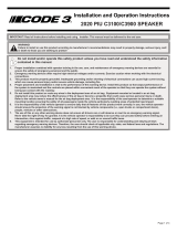
(Refer to Figure 1 for wiring diagram)
PR 1 through PR 5 - Programmable message switch input. A +12 volt applied to this input will set this function active given that igntion is
also active. These switches should be momentary.
Repeat - Repeat programmable message switch input. A +12 volt applied to this input will set this function active given that igntion is also
active.
Ignition - Ignition is recommended to be applied to the relay for ignition on vehicle.
VDD - Connect (10 AWG) to a positive +12 volt DC source.
NEG - Connect (10 AWG) to the negative terminal of the battery. This supplies ground (earth to the amplier).
SIRENINPUT SPK 1 - Connect the corresponding speaker output from a siren to this input.
SIRENINPUT COM 1 - Connect the corresponding speaker output from a siren to this input.
SIRENINPUT SPK 2 - Connect the corresponding speaker output from a siren to this input.
SIRENINPUT COM 2 - Connect the corresponding speaker output from a siren to this input.
OUTPUT 1 SPK 1 - Connect (16 AWG) from a 100 W (11 ohm) speaker to this output. Up to two 100 W (11 ohm) speakers can be
connected.
OUTPUT 1 COM 1 - Connect the other (16 AWG) from a 100 W (11 ohm) speaker to this output. Up to two 100 W (11 ohm) speakers can be
connected.
OUTPUT 2 SPK 2 - Connect (16 AWG) from a 100 W (11 ohm) speaker to this output. Up to two 100 W (11 ohm) speakers can be
connected.
OUTPUT 2 COM 2 - Connect the other (16 AWG) from a 100 W (11 ohm) speaker to this output. Up to two 100 W (11 ohm) speakers can be
connected.
Connection of a 58 watt speaker to the siren amplier will
cause the speaker to burn out, and will void the speaker
warranty!
Any electronic device may create or be aected by
electromagnetic interference. After installation of any
electronic device, operate all equipment simultaneously to
insure that operation is free of interference.
IMPORTANT WARNINGS TO USERS OF SIRENS: “Wail” and “Yelp” tones are in some cases (such as the state of California) the only
recognized siren tones for calling for the right of way. Ancillary tones such as “Air Horn”, “Hi-Lo”, “Hyper-Yelp”, and “Hyper-Lo” in
some cases do not provide as high a sound pressure level. It is recommended that these tones be used in a secondary mode to alert
motorists to the presence of multiple emergency vehicles or to the momentary shift from the primary tone as an indication of the imminent
presence of any emergency vehicle.
+ -
NEG
VDD
+12V
BATTERY
PR 5
PR 4
PR 3
PR 2
PR 1
IGNITION
REPEAT
+12V Source
SIREN INPUT COM 2
OUTPUT 1 SPK 1
OUTPUT 1 COM 1
OUTPUT 2 SPK 2
OUTPUT 2 COM 2
SIREN INPUT COM 1
SIREN INPUT SPK 2
SIREN INPUT SPK 1
100W
100W
100W
100W
SIREN
FIGURE 1

Page 4 of 5
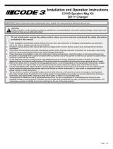
PROBLEM PROBABLE CAUSE REMEDY
NO AMPLIFIER OR SIREN OUTPUT A. SHORTED SPEAKER OR
SPEAKER WIRES. SIREN IN
OVER CURRENT PROTECTION
MODE. B. DEFECTIVE SPEAKER
A. CHECK CONNECTIONS. B. DISCONNECT SPEAKER,
LISTEN AT SIREN FOR TONES, IF TONES CAN BE
HEARD REPLACE SPEAKER.
NO AMPLIFIER OUTPUT, SIREN
OUTPUT FUNCTIONS
A. USB OR SD NOT PLUGGED
IN OR FILE STRUCTURE SET IN-
CORRECTLY. B. FUSE IS BLOWN
A. CHECK USB/SD CONNECTION AND CHECK FILE
STRUCTURE. B. CHECK FUSE. IF FUSE IS BLOWN,
CHECK POLARITY.
AMPLIFIER VOLUME TOO LOW OR
GARBLED
A. VOLUME ADJUSTMENT IS
TOO LOW. B. VOLTAGE TO
AMPLIFER IS TOO LOW. C. HIGH
RESISTANCE IN WIRING/DEFEC-
TIVE SPEAKER.
A. SET VOLUME ADJUSTMENT HIGHER. B. CHECK
WIRING FOR BAD CONNECTIONS/ CHECK VEHICLE
CHARGING SYSTEM. C. CHECK SPEAKER WIRING/RE-
PLACE SPEAKER
HIGH RATE OF SPEAKER FAILURE A. HIGH VOLTAGE TO AMPLI-
FIER. B. 58 WATT SPEAKER
CONNECTED CONNECTED TO
100 WATT TAP. 58 WATT NOT
ALLOWED.
A. CHECK VEHICLE CHARGING SYSTEM. B. USE COR-
RECT SPEAKER.
Troubleshooting
Setup and Adjustment:
Pre-Recorded Messages - Using the provided USB drive, set up a folder in the drive with the name “01”. The pre-recorded messages that
the user would like to add must be named as “001 XXX” where XXX denotes whatever name the user wants to apply. The 001 correlates to
the PR 1 input on the device and thus 002 correlates to PR 2 and so on. The le type must be a .wav le structure. Alternatively, the user can
use a SD card following the same structure.
Volume - There is a volume knob on the device that controls the volume of the pre-recorded messages. Adjust to the user’s needs.
Operation:
During operation, either the provided USB drive or a SD card must be plugged in. Ignition must be set to high for amplier to function. Siren
outputs to the speaker will pass through the amplier even if the unit is o and is only interrupted by a PR input being triggered.
PR 1 Through PR 5 - If ignition is applied to a 12 volt source and a 12 volt source is applied to one of these inputs, the corresponding pre-
recorded message should start to play. The message will only play once unless repeat input is set high. Holding the input high will not repeat
the message. This will interrupt any tones that may be active from the siren. During the active time of these inputs, if any of the inputs are set
high again it will immediately cease the message.
Repeat - If ignition is applied to a 12 volt source and a 12 volt source is applied to the repeat input as well as to a PR input, then that pre-
recorded message will play until repeat is released from 12 volts. It will immediately cease the message.
Maintenance:
The Programmable Voice Amplier siren has been designed to provide trouble free service. In case of diculty, consult the Troubleshooting
Guide of this manual. Also check for shorted or open wires. The primary cause of short circuits has been found to be wires passing through
rewalls, roofs, etc. If further diculty persists, contact the factory for troubleshooting advice or return instructions. Code 3 maintains a
complete parts inventory and service facility at the factory and will repair or replace (at the factory’s option) any unit found to be defective
under normal use and in warranty. Any attempt to service a unit, by anyone other than a factory authorized technician, without the express
written consent of the factory, will void the warranty. Units out of warranty can be repaired at the factory for a nominal charge on either a at
rate or parts and labor basis. Contact the factory for details and return instructions. Code 3 is not liable for any incidental charges related to
the repair or replacement of a unit unless otherwise agreed to in writing by the factory.
An ECCO SAFETY GROUP™ Brand
ECCOSAFETYGROUP.com
10986 North Warson Road, St. Louis, MO 63114 USA
Technical Service USA (314) 996-2800
CODE3ESG.com

Page 5 of 5
Warranty
Product Returns:
If a product must be returned for repair or replacement*, please contact our factory to obtain a Return Goods Authorization Number (RGA
number) before you ship the product to Code 3®, Inc. Write the RGA number clearly on the package near the mailing label. Be sure you use
sucient packing materials to avoid damage to the product being returned while in transit.
*Code 3®, Inc. reserves the right to repair or replace at its discretion. Code 3®, Inc. assumes no responsibility or liability for expenses incurred for the removal and /or reinstallation of products requiring
service and/or repair.; nor for the packaging, handling, and shipping: nor for the handling of products returned to sender after the service has been rendered.
Manufacturer Limited Warranty Policy:
Manufacturer warrants that on the date of purchase this product will conform to Manufacturer’s specications for this product (which are avail-
able from the Manufacturer upon request). This Limited Warranty extends for Sixty (60) months from the date of purchase.
DAMAGE TO PARTS OR PRODUCTS RESULTING FROM TAMPERING, ACCIDENT, ABUSE, MISUSE, NEGLIGENCE, UNAPPROVED MODIFICA-
TIONS, FIRE OR OTHER HAZARD; IMPROPER INSTALLATION OR OPERATION; OR NOT BEING MAINTAINED IN ACCORDANCE WITH THE
MAINTENANCE PROCEDURES SET FORTH IN MANUFACTURER’S INSTALLATION AND OPERATING INSTRUCTIONS VOIDS THIS LIMITED WAR-
RANTY.
Exclusion of Other Warranties:
MANUFACTURER MAKES NO OTHER WARRANTIES, EXPRESS OR IMPLIED. THE IMPLIED WARRANTIES FOR MERCHANTABILITY, QUALITY
OR FITNESS FOR A PARTICULAR PURPOSE, OR ARISING FROM A COURSE OF DEALING, USAGE OR TRADE PRACTICE ARE HEREBY EX-
CLUDED AND SHALL NOT APPLY TO THE PRODUCT AND ARE HEREBY DISCLAIMED, EXCEPT TO THE EXTENT PROHIBITED BY APPLICABLE
LAW. ORAL STATEMENTS OR REPRESENTATIONS ABOUT THE PRODUCT DO NOT CONSTITUTE WARRANTIES.
Remedies and Limitation of Liability:
MANUFACTURER’S SOLE LIABILITY AND BUYER’S EXCLUSIVE REMEDY IN CONTRACT, TORT (INCLUDING NEGLIGENCE), OR UNDER ANY
OTHER THEORY AGAINST MANUFACTURER REGARDING THE PRODUCT AND ITS USE SHALL BE, AT MANUFACTURER’S DISCRETION, THE
REPLACEMENT OR REPAIR OF THE PRODUCT, OR THE REFUND OF THE PURCHASE PRICE PAID BY BUYER FOR NON-CONFORMING PROD-
UCT. IN NO EVENT SHALL MANUFACTURER’S LIABILITY ARISING OUT OF THIS LIMITED WARRANTY OR ANY OTHER CLAIM RELATED TO
THE MANUFACTURER’S PRODUCTS EXCEED THE AMOUNT PAID FOR THE PRODUCT BY BUYER AT THE TIME OF THE ORIGINAL PURCHASE.
IN NO EVENT SHALL MANUFACTURER BE LIABLE FOR LOST PROFITS, THE COST OF SUBSTITUTE EQUIPMENT OR LABOR, PROPERTY
DAMAGE, OR OTHER SPECIAL, CONSEQUENTIAL, OR INCIDENTAL DAMAGES BASED UPON ANY CLAIM FOR BREACH OF CONTRACT, IM-
PROPER INSTALLATION, NEGLIGENCE, OR OTHER CLAIM, EVEN IF MANUFACTURER OR A MANUFACTURER’S REPRESENTATIVE HAS BEEN
ADVISED OF THE POSSIBILITY OF SUCH DAMAGES. MANUFACTURER SHALL HAVE NO FURTHER OBLIGATION OR LIABILITY WITH RESPECT
TO THE PRODUCT OR ITS SALE, OPERATION AND USE, AND MANUFACTURER NEITHER ASSUMES NOR AUTHORIZES THE ASSUMPTION OF
ANY OTHER OBLIGATION OR LIABILITY IN CONNECTION WITH SUCH PRODUCT.
This Limited Warranty denes specic legal rights. You may have other legal rights which vary from jurisdiction to jurisdiction. Some jurisdic-
tions do not allow the exclusion or limitation of incidental or consequential damages.
An ECCO SAFETY GROUP™ Brand
ECCOSAFETYGROUP.com
10986 North Warson Road, St. Louis, MO 63114 USA
Technical Service USA (314) 996-2800
CODE3ESG.com
© 2022 Code 3, Inc. all rights reserved.
920-0977-00Rev. A
/