Mounting instruction 17 November 2010
007986 (replaces 0179-024)
Alignment of shafts prior to coupling installation
This instruction applies to compressor units with tunnel mounted motors i.e. SAB 193, SAB 233 and SAB 283.
To secure trouble free operation the motor and compressor shafts must be properly aligned prior to installing the
coupling. This document describes the procedure used in the assembly line to measure misalignment but is also
applicable for on-site measurement.
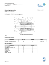
To measure the radial misalignment a dial indicator is used. The dial indicator is fastened to a rigid arm bolted firmly
to the end of the motor shaft so that the tip of the indicator touches the compressor shaft. The setup is shown in the
picture below.
Compressor
shaft Dial indicator Motor shaft
Reset the dial indicator so that the reading is 0.00 mm. Then rotate the shafts simultaneously so that the tip of the
indicator is held in the same spot on the surface of the compressor shaft. When the dial indicator reading in no time
exceeds 0.38 mm the shafts are properly aligned.
Maximum misalignment: 0.38 mm
Note: This is the method used in the assembly line to measure the misalignment, other methods can be used, but
the radial misalignment must never exceed 0.38 mm. In some cases it might prove difficult to read the dial indicator
when it is on the far side of the shafts, in these cases one can read the indicator via a small hand-held mirror. Be
careful as reading via a mirror is a possible source of error.
In case the misalignment exceeds 0.38 mm note the size of the vertical and the horizontal misalignment. To correct
vertical misalignment one adds or removes shims from under the supported feet of the motor until the dial indicator
reading is less than 0.38 mm.
Repeat the measuring procedure and the alignment procedure until the misalignment is less than 0.38 mm.
Johnson Controls Denmark ApS
Christian X's Vej 201 ∙ 8270 Højbjerg ∙ Denmark
Phone +45 87 36 70 00 ∙ Fax +45 87 36 70 05 ∙ www.sabroe.com
CVR No 19 05 61 71
Page 1 of 2

Torben Pilsgaard Hansen
Manager Uniscrew
Product Development
Direct no.: +45 87 36 77 11
Fax no.: +45 87 36 77 05
e-mail: [email protected]
Johnson Controls Denmark ApS
Christian X's Vej 201 ∙ 8270 Højbjerg ∙ Denmark
Phone +45 87 36 70 00 ∙ Fax +45 87 36 70 05 ∙ www.sabroe.com
CVR No 19 05 61 71
Page 2 of 2
/


