Page is loading ...

Page 1 of 5
Johnson Controls Denmark ApS
Christian X's Vej 201 ∙ 8270 Højbjerg ∙ Denmark
Phone +45 87 36 70 00 ∙ www.sabroe.com
CVR No 19 05 61 71
Mounting instruction
0011921
01 July 2020
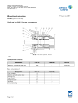
Mounting of CX–52 coupling 2125–1109 on SAB 355 screw compressor
1. Check that the Distance Between Shaft Ends (DBSE) is between 178 and 225 mm. Adjust, if necessary.
2. Pre-assemble the compressor hub and flange with the 12 M16x40 screws. Tighten crosswise to 250 Nm.
3. Lubricate the compressor shaft with thin oil. Position the compressor hub on the compressor shaft.
If DBSE is between 178 and 196 mm, place the compressor hub so that there is 178 mm free space be-
tween the motor shaft and the threaded ends of the M16x40 screws.
If DBSE is between 196 and 225 mm, align the end of the compressor hub with the shaft end.
4. Attach the compressor hub with the two mounting bolts by tightening them a little at a time to 250 Nm.
5. Pre-assemble the motor hub and flange with the 18 M12x40 screws. Tighten crosswise to 104 Nm.

Page 2 of 5
Johnson Controls Denmark ApS
Christian X's Vej 201 ∙ 8270 Højbjerg ∙ Denmark
Phone +45 87 36 70 00 ∙ www.sabroe.com
CVR No 19 05 61 71
6. Lubricate the motor shaft with thin oil. Position the motor hub on the motor shaft with a few mm free shaft
end. Rotate the shafts so that the keyways are opposite each other.
7. Pre-assemble the intermediate part (if not already assembled from factory).
Place the membrane adaptor on a workbench together with the two halves of the outer ring.
Place the first rubber ring and make sure that all the 24 M12x100 screws can be inserted in the outer ring
parts. Align the holes in the centre with the threaded holes in the membrane adaptor.

Page 3 of 5
Johnson Controls Denmark ApS
Christian X's Vej 201 ∙ 8270 Højbjerg ∙ Denmark
Phone +45 87 36 70 00 ∙ www.sabroe.com
CVR No 19 05 61 71
Place the inner ring in the centre, and align the holes with the threaded holes making sure there are threads
available under each hole.
Place the second rubber ring on top of the first rubber ring. Rotate the second rubber ring until the holes fit
over the first rubber ring and the centre ring. Avoid using the two chamfered holes in the centre.
If it is not possible to make a proper fit of all holes, remove the second rubber ring and rotate the membrane
adaptor one hole, and try again.
After obtaining a proper fit, insert the 24 M10x140 screws and make sure the threads engage one to two
turns. Insert the 24 M12x100 screws to align the rubber parts and to ensure they are positioned correctly.
Tighten the 24 M10x140 loosely to drag the parts to the correct position. Then crosswise to 60 Nm.
Remove the 24 M12x100 screws, turn the assembly upside down and remove the two outer ring parts.
Place the membrane and the membrane mounting ring on top of the membrane adaptor, and insert
the 30 M12x30 screws. Tighten them crosswise to 104 Nm.

Page 4 of 5
Johnson Controls Denmark ApS
Christian X's Vej 201 ∙ 8270 Højbjerg ∙ Denmark
Phone +45 87 36 70 00 ∙ www.sabroe.com
CVR No 19 05 61 71
8. Insert the intermediate part between the two flanges with the membrane facing the motor hub flange.
Support the intermediate part, and be careful not to damage the membrane.
Rotate the intermediate part until the two larger holes in the membrane align with the two countersunk holes
in the motor hub flange.
Insert the first half of the outer ring and align its holes with the holes in the outer rim of the rubber elements
and the threaded holes in the compressor hub flange. Rotate the compressor hub a little if necessary.
Insert the first 12 of the 24 M12x100 screws and make sure all the threads are engaged. Insert the second
half of the outer ring and the last 12 of the 24 M12x100 screws. Tighten all of the M12x100 screws cross-
wise to 104 Nm.
9. Insert the two longer spacers in the larger holes in the membrane and the two countersunk holes in the mo-
tor hub flange using two of the 16 M12x70 screws with shims and nut and finger- tighten them. Slide the mo-
tor hub on the motor shaft to keep the membrane straight. Insert the 14 shorter spacers using the last 14 of
the 16 M12x70 mm screws.
Tighten all the 16 M12x70 screws crosswise to 104 Nm, starting with the screws in the two longer spacers
and keeping the membrane straight by adjusting the motor hub.
10. Attach the motor hub with the two mounting bolts by tightening them a little at a time to 250 Nm.
11. Finally, tighten the pointed screws, which secures the key on the motor and compressor shaft, to 60 Nm.

Page 5 of 5
Johnson Controls Denmark ApS
Christian X's Vej 201 ∙ 8270 Højbjerg ∙ Denmark
Phone +45 87 36 70 00 ∙ www.sabroe.com
CVR No 19 05 61 71
A
A
Max DBSE = 225 mm
Min DBSE = 178 mm
474
SECTION A-A
M12x20 stop screw DIN 916
Tightning torqeu 60 Nm
M16x40 set screw DIN 912 grade 12.9
Tightning torqeu 250 Nm
M12x40 set screw DIN 912 grade 12.9
Tightning torqeu 104 Nm
M12x100 set screw DIN 912 grade 12.9
Tightning torqeu 104 Nm
M10x140 set screw DIN 912 grade 12.9
Tightning torqeu 60 Nm
M12x20 stop screw DIN 916
Tightning torqeu 60 Nmx
M12x70 set screw DIN 912 grade 12.9
with M12 nut ISO 7040 quality 10
Tightning torqeu 104 Nm
M12x30 set screw DIN 912 grade 12.9
Tightning torqeu 104 Nm
SCALE 1:4
SCALE 1:4
M16x60 set screw DIN 912 grade 12.9
Tightning gradually to torqeu 250 Nm
SCALE 1:4
Erik Dath
Advanced Engineering, Compressor Development
Engineering, Industrial Refrigeration (IR), Product Technology, Denmark
Building Technologies & Solutions
Tel: +45 87 36 77 89
Mob: +45 29 22 77 89
E-mail: [email protected]
www.sabroe.com
/