Publication 20D-IN027A-EN-P
6
Frame
Voltage
Code
Current
Rating
Factory Default Jumper Settings
Power Source Type
MOV/Input Filter
Caps
(1)(2)
DC Bus Common
Mode Caps
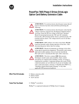
5 C
F
W
140
052
060
Two green/yellow
wires connected
to the Power
Terminal Block rail
Green/yellow wire
to CM Cap Board
is connected to
ground
Solid Ground
1. CM Cap jumper wire should be connected
to ground with a metal screw. Verify. If
necessary, remove the nylon screw/spacer
and insert a metal M5 x 8 screw. Torque to
3.2 N•m (28 lb•in).
2. MOV/Input Filter Cap jumper wires should
be connected to ground with a metal screw.
Verify. If necessary, remove the nylon
screw/spacer and insert a metal M5 x 12
screw.
Non-Solid Ground
1. CM Cap jumper wire should be insulated
from ground with a nylon screw/spacer.
Verify. If necessary, remove the metal screw
and insert a M5 x 15 nylon screw/spacer.
2. MOV/Input Filter Cap jumper wires should
be insulated from ground with a nylon
screw/spacer. Verify. If necessary, remove
the metal screw and insert a
M5 x 20 nylon screw/spacer.
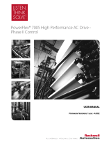
E
F
T
W
077
082
099
098
Two green/yellow
wires connected
to chassis ground
Green/yellow wire
to CM Cap Board
is connected
to
ground
Solid Ground
1. CM Cap jumper wire should be connected
to ground with a metal screw. Verify. If
necessary, remove the nylon screw/spacer
and insert a metal M5 x 8 screw. Torque to
3.2 N•m (28 lb•in).
2. MOV jumper wire should be connected to
ground with metal screws. Verify. If
necessary, remove the nylon screw/spacers
and insert metal M5 x 12 screws.
3. Input Filter Cap jumper wire should be
connected to ground with a metal screw.
Verify. If necessary, remove the nylon
screw/spacer and insert metal M5 x 8
screw.
Non-Solid Ground
1. CM Cap jumper wire should be insulated
from ground with a nylon screw/spacer.
Verify. If necessary, remove the metal screw
and insert a M5 x 15 nylon screw/spacer.
2. MOV jumper wire should be insulated from
ground with a nylon screw/spacer. Verify. If
necessary, remove the metal screws and
insert a M5 x 20 nylon screw/spacer.
3. Input Filter Cap jumper wire should be
insulated from ground with a nylon screw/
spacer. Verify. If necessary, remove the
metal screws and insert a M5 x 15 nylon
screw/spacer.
(1)
AC input drives only. MOV’s and input filter caps do not exist on DC input drives.
(2)
When removing MOV’s, the input filter capacitor must also be removed.
WIRE RANGE: 14-1/0 AWG (2.5-35 MM
2
)
TORQUE: 32 IN-LB (3.6 N-M)
STRIP LENGTH: 0.67 IN (17 MM)
USE 75 C CU WIRE ONLY
POWER TERMINAL RATINGS
WIRE RANGE: 6-1/0 AWG (16-35 MM
2
)
TORQUE: 44 IN-LB (5 N-M)
STRIP LENGTH: 0.83 IN (21 MM)
GROUND TERMINAL RATINGS (PE)
300 VDC EXT PWR SPLY TERM (PS+, PS-)
WIRE RANGE: 22-10 AWG (0.5-4 MM
2
)
TORQUE: 5.3 IN-LB (0.6 N-M)
STRIP LENGTH: 0.35 IN (9 MM)
17
21
INPUT ACOUTPUT
Optional
Communications
Module
9
CM Cap
MOV
MOV / Input Filter Cap
WIRE RANGE: 14-1/0 AWG (2.5-35 MM
2
)
TORQUE: 32 IN-LB (3.6 N-M)
STRIP LENGTH: 0.67 IN (17 MM)
USE 75 C CU WIRE ONLY
POWER TERMINAL RATINGS
WIRE RANGE: 6-1/0 AWG (16-35 MM
2
)
TORQUE: 44 IN-LB (5 N-M)
STRIP LENGTH: 0.83 IN (21 MM)
GROUND TERMINAL RATINGS (PE)
300 VDC EXT PWR SPLY TERM (PS+, PS-)
WIRE RANGE: 22-10 AWG (0.5-4 MM
2
)
TORQUE: 5.3 IN-LB (0.6 N-M)
STRIP LENGTH: 0.35 IN (9 MM)
17
21
INPUT ACOUTPUT
Optional
Communications
Module
9
PE
CM Cap
MOV
MOV
Input Filter
Cap