Page is loading ...

InstallatIon GuIde
Xtln/Xtln-WIFI Panel

MODEL XTLN/XTLN-WiFi
INSTALLATION GUIDE
FCC NOTICE
This equipment has been tested and found to comply with the limits for a Class B digital device, pursuant
to part 15 of the FCC Rules. These limits are designed to provide reasonable protection against harmful
interference in a residential installation. This equipment generates, uses and can radiate radio frequency
energy and, if not installed and used in accordance with the instructions, may cause harmful interference
to radio communications. However, there is no guarantee that interference will not occur in a particular
installation. If this equipment does cause harmful interference to radio or television reception, which can be
determined by turning the equipment off and on, the user is encouraged to try to correct the interference
by one or more of the following measures:
• Reorient or relocate the receiving antenna.
• Increase the separation between the equipment and receiver.
• Connect the equipment into an outlet on a circuit different from that to which the receiver is
connected.
• Consult the dealer or an experienced radio/TV technician for help.
Changesormodicationsnotexpresslyapprovedbythepartyresponsibleforcompliancecouldvoidthe
user’s authority to operate the equipment.
This device has been designed to operate with the integrated 1100 Series PCB antenna having a maximum
gain of 1.8 dB. Antennas having a gain greater than 1.8 dB are strictly prohibited for use with this device.
The required antenna impedance is 50 ohms.
If necessary, the installer should consult the dealer or an experienced radio/television technician
foradditionalsuggestions.Theinstallermayndthefollowingbooklet,preparedbytheFederal
Communications Commission, helpful:
“How to identify and Resolve Radio-TV Interference Problems.”
ThisbookletisavailablefromtheU.S.GovernmentPrintingOfce,WashingtonD.C.20402
StockNo.004-000-00345-4
©2015DigitalMonitoringProducts,Inc.
InformationfurnishedbyDMPisbelievedtobeaccurateandreliable.
This information is subject to change without notice.

XTLN/XTLN-WiFi Installation Guide Digital Monitoring Products
i
Table of ConTenTs
Panel Specications
1.1 .............................................................................Power Supply 1
1.2 ..........................................................................Communication 1
1.3 .................................................................................... Keypads 1
1.4 ....................................................................... Number of Zones 1
1.5 ..............................................................Enclosure Specications 1
Introduction
2.1 ................................................................System Congurations 1
2.2 ............................................................................Caution Notes 1
2.3 ............................................................. Compliance Instructions 1
System Components
3.1 ......................................................................Accessory Devices 2
Installation
4.1 ................................................... Mounting Location Information 3
4.2 .............................................................. Mounting the Enclosure 3
Primary Power Supply
5.1 ................................................................................... DC Input 3
Secondary Power Supply
6.1 ......................................................................... Standby Battery 4
6.2 ..............................................................................Replacement 4
6.3 .................................................................... Battery Supervision 4
LED Operation
7.1 ...............................................................................Backlit Logo 5
On-Board Network (XTLN only)
8.1 ................................................................................ Description 5
8.2 ............................................................................Ethernet LEDs 5
On-Board WiFi Network (XTLN-WiFi only)
9.1 ................................................................................ Description 5
9.2 ..................................................................................WiFi LEDs 5
RESET Button
10.1 .............................................................................. Description 5
Programming Connection
11.1 ..........................................................Programming Connection 5
On-Board 1100 Series Wireless
12.1 ..................................................................... Wireless Antenna 6
12.2 ............................................................ Wireless LED Operation 6
Wireless Keypads
13.1 ....................................................................Mounting Keypads 6
13.2 ..................................................... Wireless Keypad Association 6
Wireless Zones
14.1 .............................................................................. Description 6
Wireless Key Fobs and Outputs
15.1 .............................................................................. Description 6
Flash LOAD Button
16.1 .............................................................................. Description 7

Listed Compliance Specications
17.1 ..............................................................................Introduction 8
17.2 ............................................................................. Use Marking 8
17.3 ................................................................................... NFPA 72 8
17.4 ....................................................................... Types Of Service 8
17.5 ......................................................................... Bypass Reports 8
17.6 ........................................................................ Battery Standby 8
Household Burglar-Alarm System Units
ANSI/UL 1023
18.1 .............................................................................. Bell Cutoff 8
18.2 ..............................................................................Entry Delay 8
18.3 ................................................................................Exit Delay 8
18.4 ......................................................... Wireless External Contact 8
18.5 ........................................................ Wireless Supervision Time 8
18.6 ...................................................Wireless Audible Annunciation 8
18.7 .......................................................................... Panel location 8
18.8 ........................................................................ Test Frequency 8
Central Station Burglar Alarm Units
ANSI/UL 1610
19.1 ..............................................................................Supervision 9
19.2 ........................................................................Remote Disarm 9
19.3 .........................................................................Central Station 9
Household Fire Warning System
ANSI/UL 985 NFPA 72 Specications
20.1 ............................................................... Bell Output Denition 9
20.2 ................................................................... Household System 9
20.3 ........................................................ Wireless Supervision Time 9
20.4 ........................................................................ Test Frequency 9
20.5 .........................................................................Wired Modules 9
False Alarm Reduction Programmable Options ANSI/SIA CP-01-2010
19.1 ................... Shipping Defaults and Recommended Programming 10
Revisions to This Document
Certications ...............................................................................12

XTLN/XTLN-WiFi Installation Guide Digital Monitoring Products
1
Panel sPecifications
Panel Specications
1.1 Power Supply
Input: 12VDC
StandbyBattery: 3.7VDCLithium
All circuits inherent power limited
1.2 Communication
Built-innetworkcommunicationtoDMPModelSCS-1RorSCS-VRReceivers.
1.3 Keypads
Youcanconnectupto4alphanumeric9000SeriesWirelessKeypads.
1.4 Number of Zones
• XTLN/XTLN-WiFihas28wirelessinitiatingzonesnumbered1-28
• ZoneandOutputnumbers31to34and41to44cansupport1100SeriesKeyFobs,OutputModules,
or sirens
1.5 Enclosure Specications
TheXTLN/XTLN-WiFipanelshipsinaplasticenclosurewithauser’sguideandprogrammingsheet.
Size Color
5.5”Wx3.75”Hx1”D White(W)
Introduction
2.1 System Congurations
The panel can be programmed to operate as any of the following system types:
• All/Perimetersystemthatprovidesoneperimeterareaandoneinteriorarea
• Home/Sleep/Awaysystemthatprovidesoneperimeter,oneinterior,andonebedroomarea.The
bedroom area provides for any protection devices the user wants disarmed during their sleeping hours
and armed in the Away mode.
• Sixareasystemthatprovidesareasofprotectionthatcanbeindependentlyarmedordisarmed.
2.2 Caution Notes
Throughoutthisguideyouwillseecautionnotescontaininginformationyouneedtoknowwheninstalling
thepanel.Thesecautionsareindicatedwithayieldsign.Wheneveryouseeacautionnote,makesureyou
completely read and understand its information. Failing to follow the caution note can cause damage to the
equipment or improper operation of one or more components in the system.
2.3 Compliance Instructions
ForapplicationsthatmustconformtoalocalauthoritiesinstallationstandardoraNationalRecognized
TestingLaboratorycerticatedsystem,pleaseseetheListedComplianceSpecicationssectionneartheend
of this guide for additional instructions.
IntroductIon

Digital Monitoring Products XTLN/XTLN-WiFi Installation Guide
2
system components
System Components
3.1 Accessory Devices
DMP Two-Way Wireless Devices
1100R Repeater Provides additional range for wireless devices.
1101UniversalTransmitter Provides both internal and external contacts that may be used at the same time to yield two
individualreportingzonesfromonewirelesstransmitter.
1102UniversalTransmitter Provides one external contact.
1103UniversalTransmitter
Provides both internal and external contacts that may be used at the same time to yield two
individual reporting zones from one wireless transmitter. Requires EOL resistor for external
contact. ProvidesDisarm/Disablefunctionality.
1106UniversalTransmitter Provides both internal and external contacts that may be used at the same time to yield two
individualreportingzonesfromonewirelesstransmitter.
1107MicroWindowTransmitter* Provides a wireless window transmitter.
1114Four-ZoneExpander* ProvidesfourwirelesszoneswithEOLresisters.
1116RelayOutput* Provides one Form C relay.
1117LEDAnnunciator* Provides a visual system status indicator.
1119DoorSounder* Provides a wireless sounder with integrated door contact
1121PIRMotionDetector* Provides motion detection with pet immunity.
1126RPIRMotionDetector* CeilingmountmotiondetectorwithpanelprogrammablesensitivityandDisarm/Disable
functionality.
1127C/1127WPIRMotion
Detector
WallmountmotiondetectorwithpanelprogrammablesensitivityandDisarm/Disable
functionality.
1129GlassbreakDetector* Detectstheshatteringofframedglassmountedinanoutsidewallandprovidesfull-pattern
coverage and false-alarm immunity.
1131RecessedContact*
Provides concealed protection for doors, windows or other applications.
1135/1135DBSiren* Provides a wireless siren
1139BillTrap* Provides a silent alarm option for use in cash drawers.
1141WallButton* Onebuttonwallmountedwirelesstransmitter.
1142BCTwo-buttonPanicBelt
Clip Transmitter
Provides portable two-button panic operation.
1142Two-buttonPanic
Transmitter
Provides permanently mounted under-the-counter two-button panic operation.
1145-4(Four-Button)*
1145-2(Two-Button)*
1145-1(One-Button)*
KeyFobtransmittersdesignedtoclipontoakeyringorlanyard.
1161ResidentialSmokeDetector Residentialsmokedetectorwithsounder.
1162ResidentialSmokeDetector Residentialsmoke/heatdetectorwithsounderandxedrate-of-riseheatdetector.
1164WirelessSynchronized
SmokeDetector
Commercialorresidential,batterypowered,wireless,lowprole,photoelectricsmoke
detector,withsynchronizingsounder.
1183-135FHeatDetector Fixed temperature heat detector
1183-135RHeatDetector Fixed temperature and rate-of-rise heat detector
1184CarbonMonoxideDetector CarbonMonoxidedetector.
Interface Module
738ZZ-WaveInterfaceModule* ProvidesconnectionforZ-Wavemodules.
Keypads
9000SeriesLCDkeypads Allowsyoutocontrolthepanelfromvariousremotelocationsusing9000SeriesWireless
Keypads.Connectuptofour9060,9063WirelessKeypads.
9800SeriesWireless
Graphic
Touchscreenkeypads
Allowsyoutocontrolthepanelfromvariousremotelocations.Connectuptofourkeypads.
9862WirelessKeypads.
* These devices have not been investigated and shall not be used in listed installations

XTLN/XTLN-WiFi Installation Guide Digital Monitoring Products
3
InstallatIon
Installation
4.1 Mounting Location Information
A location should be selected that is centrally located between the 1100 Series transmitters used in the
installation.InstalltheXTLN/XTLN-WiFiawayfrommetalobjects.Mountingthepanelonornearmetal
surfacesimpairsperformance.Whenselectingthepropermountinglocationofatransmitter,refertothe
LEDSurveyOperationsectionofthespecicinstallationguideforthetransmitterbeinginstalled.
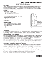
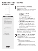
4.2 Mounting the Enclosure
The enclosure for the panel must be mounted using the provided #6 screws in the four mounting holes
showninFigure2.Mounttheenclosureinasecure,dryplaceawayfrommetalobjectstoprotectthepanel
fromdamageduetotamperingortheelements.Mountthepanelaminimumof4feetfromanywireless
transmitters or repeaters. It is not necessary to remove the PCB when installing the enclosure.
Mounting Hole Locations
Network
Connector
RESET
S1
LOAD
S2
BAT
J7
PROG
RED
PWR
MODEL XTLN
TX RF RX
SN
J1
Figure 1: Mounting Hole Locations
Primary Power Supply
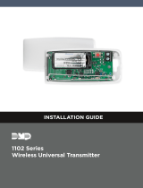
5.1 DC Input
MountthepanelnearawalloutletfortheModel372-500plug-inDCtransformer.Inadditiontopoweringthe
panel,theDCplug-intransformeralsochargestheback-upbattery.The372-500mustbelocatedwithin100
feetofthepanelusing22AWGwire.Usethefollowingstepstoconnecttheplug-intransformer:
OBSERVE POLARITY
1.Using22AWGwire,connectthepanelPWRrstterminal(+)tothepositiveterminalonthepower
supply.
2.ConnectthepanelPWRsecondterminal(-)tothenegativeterminalonthepowersupply.
3.Plugthepowersupplyintoa120VoltAC,60Hzdedicatedoutletnotcontrolledbyaswitch.
Wire Exits for DC
Power Supply
+
Model 372-500
DC Plug-in
Power
Supply
Use 22 AWG for
Power Supply connection
_
RESET
S1
LOAD
S2
BAT
J7
PROG
RED
PWR
MODEL XTLN
TX RF RX
SN
J1
Figure 2: DC Power Supply Connection

Digital Monitoring Products XTLN/XTLN-WiFi Installation Guide
4
InstallatIon
Secondary Power Supply
6.1 Standby Battery
TheXTLN/XTLN-WiFirechargeablebatteryisusedtoprovidebackupbatterypowerwhenDCpowerisnot
available.Thebatteryisintendedforbackuppoweronlyandnottooperatethepanelonadailybasis.If
the battery is low, or not plugged into the BAT battery connector, a low battery condition is indicated by the
panel.
Note:Ifremovingthepanelfromservice,disconnectthebackupbatteryfromtheBATconnector.
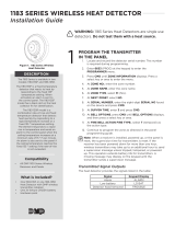
6.2 Replacement
UsethefollowingstepstoreplacetheXTLN/XTLN-WiFistandbybattery.DMPrecommendsreplacingthe
batteryevery3yearsundernormaluse.
1.Unplugthebatteryconnector(BAT)fromtheXTLN/XTLN-WiFipanel.
2.Ifinstalled,removethescrewfromthePCB.
3.LoosenthetopPCBsnaps.
4.LeanthepanelPCBforwardandliftoutfromthebottomPCBsnaps.
5. Remove and properly dispose of the used battery.
Caution:Riskofre,explosion,andburns.Donotdisassemble,heatabove212°F(100°C),
or incinerate. Properly dispose of used batteries.
6.PlacethenewbatteryintotheXTLN/XTLN-WiFihousingbasewiththebatterywiresdirectedtoward
thebottomrightcorner.SeeFigure4.
7.SettheXTLN/XTLN-WiFiPCBintothebottomsnapsandpressintothetopsnapstosecureinplace.
8.Plugthebatteryintothepanelconnector(BAT).
6.3 Battery Supervision
ThepanelteststhebatteryonceeveryhourwhenDCpowerispresent.Thistestoccurs15minutespast
eachhourandlastsforveseconds.Aloadisplacedonthebatteryandifthebatteryvoltageislow,alow
batteryisdetected.IfDCpowerhasfailed,alowbatteryisdetectedanytimethebatteryvoltagefalls
below3.7V.
RESET
S1
LOAD
S2
BAT
J7
PROG
RED
PWR
MODEL XTLN
TX RF RX
SN
J1
PCB Screw Locations
Top PCB Snaps
Bottom PCB Snaps
Battery
connector
3.7V
Rechargeable
Battery
Figure 4: Standby Battery ReplacementFigure 3: PCB Screw Locations

XTLN/XTLN-WiFi Installation Guide Digital Monitoring Products
5
InstallatIon
LED Operation
7.1 Backlit Logo
ThebacklitlogoindicatesthePowerandArmedstatusofthepanel.Dependingontheoperation,theLED
displaysinRedorGreenaslistedinthetable.
Color and Activity Operation
GreenSteady PanelDisarmed,PrimaryPowerOK,BatteryOK
GreenBlinking PanelDisarmed,PrimaryPowerOK,BatteryFault
NoLight PanelDisarmed,PrimaryPowerFault,BatteryOK
Red Steady PanelArmed,PrimaryPowerOK,BatteryOK
Red/GreenAlternate PanelArmed,PrimaryPowerOK,BatteryFault
RedBlinking PanelArmed,PrimaryPowerFault,BatteryOK
On-Board Network (XTLN only)
8.1 Description
TheETHERNETConnectorconnectsdirectlytoanEthernetnetworkusingastandardCAT-5patchcable.
8.2 Ethernet LEDs
ThetwoLEDs,locatedontheleftsideoftheETHERNETConnector,indicatenetworkoperation.Thetop,
LinkLEDisablinkinggreenlightwhenmessagesarebeingreceivedortransmitted.Thebottom,ActivityLED
ashesyellowtoindicate100Mbits/second.
On-Board WiFi Network (XTLN-WiFi only)
9.1 Description
TheXTLN-WiFiconnectsdirectlytoaWiFinetworkforencryptedTCPcommunicationusingaWireless-B/G
connection.TheXTLN-WiFiuseswireless802.11b/gWiFitechnology,whichcantravel125ft.indoorsandcan
reachoutto460ft.outdoorswithaclearlineofsight.
Note:RangeforWiFicommunicationhasnotbeeninvestigatedbyUL.
9.2 WiFi LEDs
ThetwoWiFiLEDs,locatedinthecenterofthecircuitboard,indicatenetworkoperation.Theleft
WiFi-1LEDisagreenlightthatissolidwhenthenetworkisconnectedandblinksonandoffwhenthereisno
networkconnectivity.TherightWiFi-2LEDisayellowlightandblinkswhenmessagesarebeingreceivedor
transmitted.
RESET Button
10.1 Description
TheRESETbuttonislocatedontherightsideofthecircuitboardandisusedtoresettheXTLN/XTLN-WiFi
microprocessor.Toresetthepanelpriortoreprogramming,presstheRESETbuttonwithoutpoweringdown
thesystem.Afterresettingthepanel,beginprogrammingwithin30minutes.Ifyouwaitlongerthan30
minutes, you must reset the panel again.
Programming (PROG) Connection
11.1 Programming Connection
Alocking4-pinPROGheaderisprovidedtoconnectakeypadwhenusingaDMPModel330Programming
Cable.ThisprovidesaquickandeasyconnectionforprogrammingtheXTLN/XTLN-WiFipanel.After
programmingiscomplete,removethekeypad.
Installing the 738Z
Toconnectthewiringofthe738ZtothePROGheaderofthepanel,useaPC-0140ConnectorAssembly
(includedwiththe738Z)forconnectionofaModel300harness.WhenusedwiththeXTLN/XTLN-WiFi,the
738Zoperatesusingthebackupbatterywhenprimarypowerisnotpresent.
Note:ThePROGheaderisnotintendedtoprovideaKeypadDataBusconnection.Theprogrammingkeypad
is operational only when primary power is applied to the panel.

Digital Monitoring Products XTLN/XTLN-WiFi Installation Guide
6
InstallatIon
On-Board 1100 Series Wireless
12.1 Wireless Antenna
TheXTLN/XTLN-WiFiWirelessAntennaisintegratedintothecircuitboard.Thepanel’sbuilt-inwireless
receiveroperateswithDMP1100Seriestransmitters.Seesection3.1foralistofaccessorydevices.
12.2 Wireless LED Operation
Green (TX):ThegreenLEDasheseverytimethereceivertransmits(32timespersecond).Ifthepanel
isreset,orthepanelispoweredoff,thegreenLEDisoff.Undernormaloperation,thegreenLEDashes
constantly with no interruption or change.
Yellow (RX):TheyellowLEDasheseverytimethepanelreceivesamessagefromaprogrammedwireless
transmitter.Whenamessageissentbyatransmitter,typicallybypressingorreleasingthetamperswitch,
theyellowLEDshouldashindicatingthatthepanelreceivedamessagefromthetransmitter.IftheLED
neverashes,thetransmitterisnotgettingthroughtothepanel.Thiscouldbebecauseofamisprogrammed
serialnumberorthetransmitteristoofaraway.Undernormaloperation,theyellowLEDashesatevery
tripofeverywirelesstransmitterandwhenthetransmittersperformtheirperiodiccheck-in.Itisnot
unusualforthisLEDtostayoffformanyminutesatatimewhennotransmittersarecommunicating.
Wireless Keypads
13.1 Mounting Keypads
DMPkeypadshaveremovablecoversthatallowthebasetobemountedonawall,deskstandorotherat
surface using the screw holes provided on each corner.
13.2 Wireless Keypad Association
EnableWirelessKeypadAssociationoperationonboththekeypadandpanel.
Toenableassociationoperationinthekeypad,accesstheInstallerOptionsMenu(3577(INST)).Thekeypad
logoLEDsturnoffuntilassociationissuccessful.Referto9000SeriesWirelessKeypadInstallationGuide
LT-1107orthe9862SeriesWirelessGraphicsKeypadInstallationGuideLT-1367formoreinformation.
To enable association in the panel, reset the panel three times as described below and observe the operation
ofGreenLEDandRedBacklitLogoLED’s.SeeFigure5forBacklitLogoLEDlocation.
1. PressRESET.
2. TheGreenLEDturnsoff.
3. TheGreenLEDandRedLEDturnonsteadythenoff.
4. TheGreenLEDturnsonagain.
Repeatsteps1-4twomoretimesoruntilboththeGreenLEDand
RedLEDremainonsteady.
For60secondsthepanellistensforwirelesskeypadsthatareinthe
InstallerOptionsMenu(3577CMD)andhavenotbeenprogrammed,
orassociatedintoanotherpanel.Wirelesskeypadsareassignedto
therstopendevicepositionautomaticallybasedupontheorderin
whichtheyaredetected.ThekeypadlogoturnsGreentoindicateit
has been associated with the panel.
Wireless Zones
14.1 Description
XTLN/XTLN-WiFipanelsprovide28wirelesszonesnumbered1to28.Adefaultzonename,zonetype,and
areaassignmentaredescribedintheXTLN/XTLN-WiFiProgrammingGuide(LT-1221)andcanbechangedin
Zone Information programming as needed. The defaults are provided as a programming convenience to help
reduce installation time.
Wireless Key Fobs and Outputs
15.1 Description
XTLN/XTLN-WiFipanelsprovide8wirelesskeyfoboroutputaddressesnumbered31to34and41to44.
A default name is provided as a programming convenience to help reduce installation time. The default
namesaredescribedintheXTLN/XTLN-WiFiProgrammingGuide(LT-1221)andcanbechangedinOutput
Information or Zone Information programming as needed.
+
_
RESET
S1
LOAD
S2
BAT
J1
PROG
RED
PWR
MODEL XTL
TX RF RX
S
N
CR7
CR6
Red LED
Green LED
Figure 5: XTLN/XTLN-WiFi Backlit
Logo LED’s

XTLN/XTLN-WiFi Installation Guide Digital Monitoring Products
7
InstallatIon
Flash LOAD Button
16.1 Description
TheXTLN/XTLN-WiFipanelsoftwarecanbeupdatedviathepanel’sProgramming(PROG)header.Toupdate
the panel with a new software version, complete the following steps at the protected premise:
Model 399 Cable
1.ConnectaDMP399CablefromthePROGHeadertotheserialportofyourPCoperatingRemoteLinkand
containingtheXTLN/XTLN-WiFiRUle.
2.StartRemoteLinkandcreateoropenthecontrolpanelaccountthatmatchesthepaneltobeupdated.
3.SettheConnectionInformationTypetoDirectwithabaudrateof38400andchoosetheappropriate
COMport.
4.SelectPanel>RemoteUpdate,thenselectthecorrectRUleforthepanel.
5.PressandholdtheLOADbutton,thenpressandreleasetheRESETbutton.
6.ReleasetheLOADbuttonandclick<Update>inRemoteLink.
7.Afterthesoftwareupdateiscompleted,removethe399cableandpresstheRESETbuttontoresume
normal panel operation.
Model 400 USB Flash Module
1.PressandholdtheLOADswitch.WhileholdingtheLOADswitch,pressandreleasetheRESETswitch
2.ReleasetheLOADswitch.
3.ConnecttheUSBashdrivetotheModel400andconnecttheassemblytothepanelsPROGheader.The
LEDontheModel400willashanddisplaysteadygreen.
5.PressandreleasetheloadbuttonontheModel400toinitiatethermwareupdate.TheLEDonmodel
400willashslowly.IftheLEDdisplaysfastashesitmeansthermwareupdatewasunsuccessful.
6.Theupdatewilltakeapproximately4.5minutesandwhencompletetheLEDontheModel400will
display steady green.
7.PressandreleasetheRESETswitchthenremovetheUSBashdriveandModel400assembly.For
additionalinformationseeModel400USBFlashModuleInstallationGuide(LT-1402).

Digital Monitoring Products XTLN/XTLN-WiFi Installation Guide
8
COMPLIANCE
Listed Compliance Specications
17.1 Introduction
Theprogrammingandinstallationspecicationscontainedinthissectionmustbecompletedwhen
installingtheXTLN/XTLN-WiFiinaccordancewithanyoftheANSI/ULorSIAburglarystandards.Additional
specicationsmayberequiredbyaparticularstandard.
17.2 Use Marking
CommercialCentralStation,HouseholdBurglarandFireControlUnit.
17.3 NFPA 72
ThisequipmentshouldbeinstalledinaccordancewithChapter11oftheNationalFireAlarmCode,
ANSI/NFPA72-2002,(NationalFireProtectionAssociation,BatterymarchPark,Quincy,MA02269).Printed
information describing proper installation, operation, testing, maintenance, evacuation planning, and repair
serviceistobeprovidedwiththisequipment.Warning:Owner’sinstructionnotice,nottoberemovedby
anyone except occupant.
17.4 Types Of Service
SuitableforCentralStationBurglar.SuitableforHouseholdFireandHouseholdBurglar.Testweekly.
17.5 Bypass Reports
ThebypassreportsmustbeprogrammedasYESforalllistedburglaryapplications.
17.6 Battery Standby
TheXTLN/XTLN-WiFiisshippedwithabatteryfor24hourbatterystandbyoperation.
Household Burglar-Alarm System Units
ANSI/UL 1023
18.1 Bell Cutoff
Thebellcutofftimecannotbelessthan4minutes.
18.2 Entry Delay
Themaximumentrydelayusedmustnotbemorethan45seconds.
18.3 Exit Delay
The maximum exit delay used must not be more than 60 seconds.
18.4 Wireless External Contact
Whenused,theExternalContactof1101,1102,or1106transmittersmustbeprogrammedNormallyClosed.
18.5 Wireless Supervision Time
TheZoneInformationSupervisionTimecannotbesetto0(zero).
18.6 Wireless Audible Annunciation
TheWirelessAudibleoptionmustbeselectedasDAYforresidentialapplications.
18.7 Panel location
Mountpanelinsideprotectedarea.
18.8 Test Frequency
TheTestFrequencyoptionmustbeprogrammedtosendareportatleastonceevery30days.

XTLN/XTLN-WiFi Installation Guide Digital Monitoring Products
9
COMPLIANCE
Central Station Burglar Alarm Units
ANSI/UL 1610
19.1 Supervision
CommercialBurglaryisprovidedwhentheCheck-inandFailTimetimeissetto3minutes.
19.2 Remote Disarm
REMOTEDISARMmustbeprogrammedasNO.
19.3 Central Station
MESSAGETOTRANSMITprogrammingforzonesmustnotbesettoLOCAL(L).
Household Fire Warning System
ANSI/UL 985 NFPA 72 Specications
20.1 Bell Output Denition
The wireless siren of the panel must be programmed to operate steady on burglary alarms and temporal on
realarms.SeetheXTLN/XTLN-WiFiProgrammingGuide(LT-1221).
20.2 Household System
An alarm sounding device must be installed indoors so that it is clearly heard in all sleeping areas.
20.3 Wireless Supervision Time
TheZoneInformationSupervisionTimemustbe3minutesforredevices.SeetheXTLN/XTLN-WiFi
ProgrammingGuide.
20.4 Test Frequency
TheTestFrequencyoptionmustbeprogrammedtosendareportatleastonceevery30days.
20.5 Wired Modules
ModulesthatconnecttothePROGheader,suchasthe738Z,mustnotbeusedsincethebatterystandby
timewillbereducedbelowthe24hourminimum.

Digital Monitoring Products XTLN/XTLN-WiFi Installation Guide
10
COMPLIANCE
False Alarm Reduction Programmable Options ANSI/SIA CP-01-2010
19.1 Shipping Defaults and Recommended Programming
SIA CP-01 FEATURE
PARAGRAPH # AND
DESCRIPTION
DMP PROGRAMMING
GUIDE LT-1221
SECTION #
REQUIREMENT RANGE
SHIPPING
DEFAULT
RECOMMENDED
PROGRAMMING*
4.2.2.1ExitTime 8.6ExitDelay
Required
(Programmable)
45sec.-250sec.
60
Seconds
60 Seconds
4.2.2.2Progress
Annunciation
13.13Prewarn
Address
Allowed
Individualkeypadsmay
bedisabledperzone
All
keypads
enabled
Allkeypads
enabled
4.2.2.3ExitTimeRestart 8.6ExitDelay RequiredOption
For re-entry during exit
time
Enabled Enabled
4.2.2.5AutoStayArmon
UnvacatedPremises
8.15Occupied
Premise - See Install
Guide
RequiredOption
(exceptforremote
arming)
OccupiedPremiseNO/
YESoption
Enabled
EnabledYes
for Residential
Applications
4.2.4.4ExitTimeand
Progress Annunciation/
Disable-forRemoteArm
NotAvailableon
Remote Arming
AllowedOption
Progress Annunciation
Always disabled for
Remote Arming
Not
Available
Remote Arming not
allowed for CP-01
installations.
4.2.3.1EntryDelay(s) 8.5EntryDelay
Required
(Programmable)Only
useEntryDelay1.Do
notuseEntryDelay2.
30sec.–240Sec.**
30
Seconds
Atleast30
Seconds **
4.2.5.1AbortWindow–
forNon-FireZones
3.3TransmitDelay RequiredOption
Disablebyzoneorzone
type
Enabled
NTDYEX
Zone
Enabled
4.2.5.1AbortWindow
Time–forNon-FireZones
3.3TransmitDelay
Required
(Programmable)
20sec.,30sec.,or
40sec.**
30
Seconds
Atleast20
Seconds **
4.2.5.1.2Abort
Annunciation
3.3TransmitDelay RequiredOption
Annunciate that no
alarm was transmitted
Yes Yes
4.2.5.4.1Cancel
Annunciation
AlwaysEnabled-Not
Programmable
RequiredOption
Annunciate that a
Cancel was transmitted
(S49)
Always
Enabled
Yes
4.2.6.1&4.2.6.2Duress
Feature
UserCode+1=
AmbushCodeNot
Available
AllowedOption
No1+derivativeof
another user code/no
duplicates with other
user codes
Code+1
Always
Disabled
NotProgrammable
4.3.1CrossZoning 13.16CrossZone RequiredOption
Yes/NoZone
Programming
No
Enabledusing
two or more
programmedzones
4.3.1ProgrammableCross
Zoning Time
8.7CrossZoneTime Allowed 4sec.-250sec. 0 Seconds
Perwalkpath
in protected
premises
4.3.2SwingerShutdown
NotAvailable—
AlwaysOn
Required 1-6 trips 2trips 2trips
4.3.2SwingerShutdown
Disable
13.12SwingerBypass Allowed
For non-police
responsezones
Yes Enabled(allzones)
4.3.3FireAlarm
Verication
13.5ZoneType RequiredOption FV Type Zone No
Yes as required
(unlesssensorscan
selfverify)
4.6.3SystemTest 16.6WalkTest Allowed
Test all protection
devices
N/A N/A
4.6.5Communications 16.6WalkTest NotAllowed N/A N/A N/A
*Programmingatinstallationmaybesubordinatetootherlistedrequirementsfortheintendedapplication.
**ForlistedInstallations,combinedEntryDelayandTransmitDelayshouldnotexceed1minute.
LocalBell
Allnon-rezonessuchasNight,Day,Exit,Aux1andAux2mustbeprogrammedforlocalbellenabledwithabellcutofftimeset
toaminimumof6minutestoprovideacancelwindowof5minutesorgreater.Thisdoesnotapplytomanuallyoperatedzone
typessuchasPanicandEmergency.
TherequirementsaresupersededbyanyrequirementsforCommercialBurglar,HouseholdFireWarning,orHouseholdBurglar
applications.
MinimumInstallationRequirements:SIACP-01-2010minimumsysteminstallationrequirementsincludeanXTLN/XTLN-WiFi,an
1135WirelessSiren,a9000SeriesWirelesskeypad,andcommunicationtoanSCS-1Rreceiver.

XTLN/XTLN-WiFi Installation Guide Digital Monitoring Products
11
Revisions
Revisions to This Document
Thissectionexplainsthechangesmadetothisdocumentduringthisrevision.Itliststhedateandidenties
thechange(s)made,therelatedsectionnumberandsectionheading,andasummaryofthechange.
Ver. Section Number and Heading Quick Explanation of Changes
1.02 EntireDocument AddedreferencesandinformationforXTLN-WiFi
1.01 EntireDocument InitialRelease

800-641-4282
www.dmp.com 2500 North Partnership Boulevard
LT-1220 1.02 © 2014 Digital Monitoring Products, Inc.
15435
Certications
CaliforniaStateFireMarshal(CSFM)
FCCWirelessReceiverApprovals
FCCPart15ID:CCKPC0117
IndustryCanadaID:5251A-PC0117
FCCWiFiNetworkApprovals
FCCID:XM5-SM2144SMT
IndustryCanadaID:8516A-SM2144SMT
ANSI/UL1023 HouseholdBurglar
ANSI/UL985 HouseholdFireWarning
ANSI/UL1610 CentralStationBurglar
/