Page is loading ...

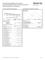
Center Zone Back Zone
Workrite Ergonomics | 800.959.9675 www.workriteergo.com 1 of 2
A Face Plate
Bracket
Qty: 1 D #10–32 × ⅝" Pan Head
Screws
Qty: 6 E #10–32 × ¾" Pan Head
Screws
Qty: 6
B Track Bridge
Brackets
Qty: 2
F Spacers, ¼"
Qty: 6
C #10–32 × ⅜" Pan Head
Screws
Qty: 6
G Spacers, ⅜"
Qty: 6 H #10–32 Keps Nuts
Qty: 6
I #12 × ¾" Wood Screws
Qty: 6
Verify that you have all the hardware needed for the assembly.
Phillips-head screwdriver ⅜" driver or wrench Drill/Driver with " drill bit
"
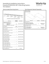
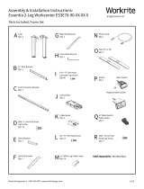
Attach Brackets to Keyboard Arm Track
The Bench Mount Kit can be configured in three
dierent heights. See chart at right for hardware
recommendations.
Attach the Face Plate Bracket using two Pan Head
Screws (C, D or E). Insert through the front most
holes in track from below. Use Spacers (none, F or
G) as required between track and bracket. Install
two Keps Nuts (H) and tighten securely.
Attach Track Bridge Bracket to the Center Zone of
Keyboard Arm Track, using two Pan Head Screws
(C, D or E). Insert through the holes in the track
best suited to avoid obstructions as far forward as
possible. Use Spacers (none, F or G) as required
between track and bracket. Install two Keps Nuts
(H) and tighten securely.
Attach Track Bridge Bracket to the Back Zone of
Keyboard Arm Track, using two Pan Head Screws
(C, D or E). Insert through the holes in the track
best suited to avoid obstructions as far rearward
as possible. Use Spacers (none, F or G) as required
between track and bracket. Install two Keps Nuts
(H) and tighten securely.
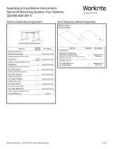
Assembly Instructions:
Bench Mount Kit, BKM-2-B
Parts Included
Required, sold separately
Worksurface
Keyboard Arm
1
✓
a
a
bb
c
c
A
B
B
CDE
or
or
see chart
see chart
FG
H
Spacing Chart
Height Spacer Screw
1⅞" None C
2⅛" F D
2¼" G E

Workrite Ergonomics | 800.959.9675 www.workriteergo.com 2 of 2
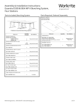
Attach Track Assembly to Worksurface
Locate appropriate area under worksurface for track. Face Plate must be placed a minimum of ½" in from front
edge of worksurface. Mark holes on surface. Using " drill bit, drill pilot holes ¾" deep.
Do not drill through worksurface!
Use #3 Phillips-head screwdriver to attach arm and track using six #12 ×¾" Wood Screws (F).
2
Obstruction
½" Minimum
#1500219 - Rev B
Mark your drill bit
at 3/4” or use a drill
stop or you may
damage your top!
I
/