
• BDD-652 Operator's Guide Page 1 • BDD-652 Operator's Guide Page 1
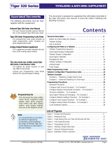
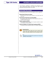
BDD-652
Magnetostrictive
Start / Stop Controller
Operator’s Guide
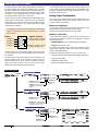
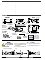
Introduction
The BDD-652 is a magnetostrictive start / stop interface with a
6-digit alpha-numeric display contained in an 1/8 DIN case. The
modular construction of the BDD-652 allows for a variety of
relay, analog, and serial output options using plug-in type out-
put cards.
The five button format provides instant access to the following
programming menus. Once the output options have been con-
figured in the main programming mode, magnetostrictive set-
tings relevant to a specific sensor can be easily configured
through the main and setpoint menus by pressing the or
button.These menus provide easy to use message prompts to
configure the BDD-652 for up to four magnet displacement
inputs.
P
Specications
TDC................................ACAM Time-to-digital convertor 250 ps
time resolution (typical).
Multi-hit Capability ........Up to 4 independent magnets read con-
currently (representing 4 displacements).
Transducer Interface......Start / Stop (RS422 differential).
Typically leading edge, but can be leading
or trailing edge.
Signal Proc. Rate ..........100 Hz.
Units ..............................Select inches or millimeters.
Max. Sensor Length......Inches: 165.
Meters: 4.
Resolution......................Inches: 0.01, 0.001, or 0.0001.
Millimeters: 0.1, 0.01, or 0.001.
Number of Magnets ......One to four.
Count Direction..............Positive or negative.
Gradient........................Inches: 8.0000 to 11.0000 (µs/inch).
Millimeters:2000.0 to 3500.0 meters/sec.
Home Position..............Magnet 1: from –199999 to 999999
counts.
Displacement................Selectable 1-4 independent position cal-
culations.
Velocity ..........................Selectable 1-4 independent velocity calcu-
lations.
Relay Outputs................Up to six 5 A relays, or combinations of
10 A and 5 A relays. Contact Balluff for
details.
Setpoint Control ............Choice of 6 setpoint sources and inverted
logic for latched digital outputs.
Analog Output................Single Output: Fully scalable, isolated 16-
bit from 0 to 10 VDC (or reverse),or 0/4 to
20 mA (or reverse).
Dual Output: Fully scalable, 16-bit dual 0 to
10 VDC (or reverse), sharing common 0.
Serial Output..................Choice of either RS-232 or RS-485.
Advanced Functions......A number of advanced functions are
available and can be added at minimum
cost. See Page 22.
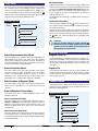
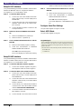
Provides easy-to-use message
prompts to configure the BDD-652
for up to 4 magnets.
P
4 secs
Main Menu
Provides easy-to-use message
prompts to configure up to 6 simple
setpoint and relay settings.
Setpoint
Menu
Allows you to set a physical start or
ʻhomeʼposition for magnet 1.
Set Home
Position
This mode contains all the menus to
configure the built-in functions of
the controller, including the analog
and serial output settings.
Main
Programming
Mode
P
This mode contains all the menus to
configure the controller for sophisti-
cated setpoint and relay settings,
including hysteresis, deviation,
timers, and much more.
Setpoint
Programming
Mode
P
•6-digit, 0.56” (14.2 mm) Alphanumeric Display
•5-button Programming
This mode allows you to view the
positions of all the magnets.
View Mode
This mode allows you to view the
activation settings of all six set-
points.
View Mode
•1/8 DIN Case

Page 2 • BDD-652 Operator's Guide
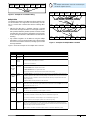
Select Measurement Units Mode
This menu allows you to select the unit of measurement for all
other settings. If you select inches in this menu, then all other
menus ask for settings to be entered in inches. Conversley, if
you select millimeters in this menu, then all other menus ask for
settings to be entered in millimeters [MM].
Select Resolution Mode
This menu allows you to select the resolution of the display
positional readings in either hundredths (0.01), thousandths
(0.001), or ten thousandths (0.0001) of an inch. Or, if set to
millimeters as the measurement unit in either tenths (0.1),
hundredths (0.01), or thousandths (0.001) of a millimeter.
Select Number of Magnets Mode
This menu allows you to select the number of magnets you
require for your application. You can select from one to four
magnets.
Enter Calibration Factors Menu
This menu allows you to configure calibration factors in the
following sub-menus.
Select Count Direction Menu
This menu allows you to configure the controller to read in
positive or negative units from the home position of magnet 1.
Magnet 1 is the magnet closest to the transducer’s zero / null
position (normally shown by a groove cut in the transducer
mounting rail).
Select Transducer Type Menu
This menu allows you to select the type of transducer installed.
The transducer type is normally shown on the transducer
nameplate as part of the serial number: either Tfor trailing edge
or Lfor leading edge.
Main Menu Set Gradient Menu
This menu allows you to set the gradient setting in either micro
seconds per inch or meters per second, depending on the units
selected in the select measurement units mode.When set to
the default resolution, the minimum to maximum gradient set-
ting is 8.0000 to 11.0000 microseconds/inch or 2000.0 to
3500.0 meters/second.
The gradient for the transducer is normally shown on the trans-
ducer label.
Set Home Position Menu
This menu works together with the button. It allows you to
set a physical start or ‘home’position and a display home posi-
tion setting for magnet 1.
The display home position setting can range from –199999 to
999999 counts.When the display home position has been con-
figured, move magnet 1 to its physical home position and press
the button. This resets the display to the configured home
setting for magnet 1.
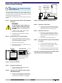
CAUTION:
This is a one-time setting for magnet 1. Button
should not be pressed again while the process is in
operation.The home setting should only be reset at
the beginning of a new process.
Setpoint Menu
The setpoint menu is where simple setpoint settings are con-
figured using easy-to-follow message prompts that guide you
through the following menus.
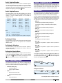
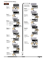
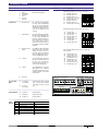
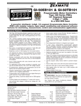
Main Menu Logic Tree
Select Measurement Units Mode
Start 4 secs
Select Resolution Mode
Select Number of Magnets Mode
Enter Calibration Factors Menu
P
Operational
Display
P
P
P
P
Setpoint Menu Logic Tree
Start Select Setpoint Number Mode
Select Setpoint Source Mode
Set Setpoint Value Mode
Set Setpoint Activation Mode
Select Setpoint Number Mode
EXIT
Operational
Display
P
P
P
P
P
The main menu is where the magnetostrictive sensor settings
are configured using easy-to-follow message prompts that
guide you through all relevant settings. When changing sen-
sors, reconfiguration is easily carried out by pressing the
button for 4 seconds and entering the main menu.The message
prompts lead you through the following menus.
P
Program Lock Pin
To prevent tampering or inadvertent changes to settings, con-
necting the PROGRAM LOCK pin (pin 8) to the COMMON pin
(pin11) locks all macro and operating system code menus and
also the home position. All readings can still be viewed in the
view modes.
Capture Pin
Connecting the CAPTURE pin (pin 12) to the COMMON pin
(pin11) performs the same function as the F1 button.The switch
must be made for at least 300 ms on the down edge for the
home position to be set.
External Switches

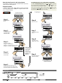
• BDD-652 Operator's Guide Page 3
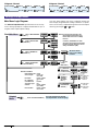
[MAG 1]
[MAG_2]
[VEL_1]
[VEL_2]
[M2 – M1]
1 Magnet
[MAG 1]
[VEL_1]
2 Magnets
[MAG 1]
[MAG_2]
[MAG_3]
[VEL_1]
[M2 – M1]
[M3 – M2]
3 Magnets
[MAG 1]
[MAG_2]
[MAG_3]
[MAG_4]
[M2 – M1]
[M3 – M2]
[M4 – M3]
4 Magnets
Set Setpoint Value
This menu allows you to set the value that the selected setpoint
activates at. This value can be anywhere from –199999 to
999999 counts.
Set Setpoint Activation
This menu allows you to select how the selected setpoint is
activated, either below the setpoint value [LOW] or above the
setpoint value [HIGH].
Exiting the Setpoint Menu
When the four setpoint settings are configured, the menu returns
to the [SET SETPOINT NUMBER] menu. To exit the setpoint
menu, press the button.When [EXIT] is displayed, press the
button.The meter returns to the operational display.
P
Select Setpoint Number
This menu allows you to select one of the six available setpoints
and applies the following menu settings to it. All six setpoints
can be configured in this way. When one setpoint has been
configured, return to the operational display and then enter the
setpoint menu again by pressing the button.
Main Programming Mode
This mode has nine built-in code menus to configure all the
functions contained in the controller. Only the following modes
should be entered for BDD-652 configuration settings:
•Calibration Mode [CAL]
–Serial Port Settings.
–Analog Output Calibration.
•Code 1
–Data Source for Serial Port.
–Data Source for Analog Output.
•Code 3
–Select ASCII Mode.
Select Setpoint Source
This menu allows you to select the activation source for the
selected setpoint from one of the following settings. Note, the
number of sources available depends on the number of
magnets selected:
Note:
[MAG 1] = Position of magnet 1
[VEL_1] = Velocity of magnet 1
[M2 – M1] = Position of magnet 2 minus position of magnet 1
Setpoint Programming Mode
The setpoint programming mode provides sophisticated set-
point settings that include setpoint latching, reset, tracking, hys-
teresis and deviation, PID, and seven timer modes. These are
advanced setpoint settings. For full details contact Balluff.
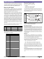
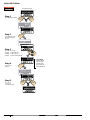
The view mode allows you to display the positional readings of
all installed magnets. The positional reading for magnet 1 is
displayed when the controller is in the operational display.
You can change the reading displayed in the operational display
from magnet 1 to any of the following view mode displays.This
depends on the number of magnets required and selected for
the application.The list is for the maximum of four magnets:
•[MAG_1]
This displays the positional reading of magnet 1.
The magnet 1 reading is the default operational display.
•[MAG_2]
This displays the positional reading of magnet 2.
•[MAG_3]
This displays the positional reading of magnet 3.
•[MAG_4]
This displays the positional reading of magnet 4.
•[VEL_1]
This displays the velocity of magnet 1.
•[VEL_2]
This displays the velocity of magnet 2.
•[M2 – M1]
This displays the position of magnet 2 minus the position of
magnet 1.
•[M3 – M2]
This displays the position of magnet 3 minus the position of
magnet 2.
•[M4 – M3]
This displays the position of magnet 4 minus the position of
magnet 3.
To change the reading on the operational display from [MAG 1] to
one of the above displays, press the button until the display
you require appears.Press the button, the new reading now
becomes the operational display.
P
View Modes
1 Magnet Selected
[MAG 1] [VEL_1]
Operational Display
P
2 Magnets Selected
[MAG 1] [MAG_2] [VEL_1]
[VEL_2]
[M2 – M1]
Operational Display
P
3 and 4 Magnets Selected continued on next page

Page 4 • BDD-652 Operator's Guide
[ _ _SELECT MEASUREMENT
UNITS ]
4 Secs
Start NOTE: If inches has been selected as the
measurement unit in the first menu,
then all other menus ask for settings
in inches.
Conversley, if millimeters has been
selected as the measurement unit in the
first menu, then all other menus ask for
settings in millimeters [MM].
[ _ _SELECT RESOLUTION
IN INCHES ]
[ _ _SELECT NUMBER OF
MAGNETS ] Prog.
SP1 SP2 SP4SP3 SP5 SP6
[ _ _ENTER CALIBRATION
FACTORS MENU ]
[ _ _SELECT
COUNT
DIRECTION ]
[ _ _SELECT IF
TRANSDUCER
IS P OR M TYPE ]
[ _ _SET
GRADIENT
IN MICRO
SECONDS/
INCH ]
Min 8.0000 inches
2000.0 mm
Max 11.0000 inches
3500.0 mm
[ _ _SET HOME
POSITION FOR
SENSOR ] Min -19.9999 inches
-199.999 mm
Max 99.9999 inches
999.999 mm
0.0001 0.001
0.01
All menus shown
here are for settings
in inches
DEFAULT SETTINGS
Measurement Units: Inches
Sensor Length: Inches = 50
mm = 1500
Resolution: Inches = 0.0001
mm = 0.001
No. of Magnets: 2
Count Direction: Positive
Transducer Type: M1
Gradient: Inches = 9.0000
mm = 2800.0
Home Position: Inches = 0.0000
mm = 0.000
[ _ _ _ _ SELECT SETPOINT NUMBER ]
Main Menu
Setpoint
Menu For a full setpoint logic diagram,
see Setpoint Menu on the next page
SP1 SP2 SP3 SP4 SP5 SP6
F2
P
F1
SP1 SP2 SP3 SP4 SP5 SP6
F2
P
F1
SP1 SP2 SP3 SP4 SP5 SP6
F2
P
F1
SP1 SP2 SP3 SP4 SP5 SP6
F2
P
F1
SP1 SP2 SP3 SP4 SP5 SP6
F2
P
F1
SP1 SP2 SP3 SP4 SP5 SP6
F2
P
F1
SP1 SP2 SP3 SP4 SP5 SP6
F2
P
F1
SP1 SP2 SP3 SP4 SP5 SP6
F2
P
F1
SP1 SP2 SP3 SP4 SP5 SP6
F2
P
F1
SP1 SP2 SP3 SP4 SP5 SP6
F2
P
F1
SP1 SP2 SP3 SP4 SP5 SP6
F2
P
F1
SP1 SP2 SP3 SP4 SP5 SP6
F2
P
F1
SP1 SP2 SP3 SP4 SP5 SP6
F2
P
F1
SP1 SP2 SP3 SP4 SP5 SP6
F2
P
F1
SP1 SP2 SP3 SP4 SP5 SP6
F2
P
F1
SP1 SP2 SP3 SP4 SP5 SP6
F2
P
F1
F2
P
P
P
PP
P
P
P
P
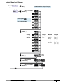
Main Menu Logic Diagram
Message Prompt Menus
The main and setpoint menus provide instant access to easy-
to-use message prompts to configure the BDD-652 for up to 4
magnets and 6 simple setpoint settings.
Once the output options have been configured (analog and
serial output), magnetostrictive settings relevant to a specific
sensor can be easily configured through the main and setpoint
menus by pressing the or button.
P
[MAG 1] [MAG_2] [MAG_3]
[MAG_4]
[M2 – M1]
[M3 – M2]
[M4 – M3]
3 Magnets Selected
Operational Display
[MAG 1] [MAG_2] [MAG_3]
[VEL_1]
[M2 – M1]
[M3 – M2]
Operational Display
4 Magnets Selected
P
P

• BDD-652 Operator's Guide Page 5
[ _ _ _ _ SELECT SETPOINT
NUMBER ]
[ _ _ _ _ SELECT SETPOINT
SOURCE ]
[ _ _ _ _ SET SETPOINT
VALUE ]
[ _ _ _ _ SET SETPOINT
ACTIVATION ]
Min -199999
Max 999999
[ _ _ _ _ SELECT SETPOINT
NUMBER ]
buttons
[ _ _SELECT MEASUREMENT
UNITS ]
4 Secs
Start Main Menu
Setpoint
Menu
For a full Main Menu logic diagram,
see Main Menu on the previous page
P
P
F2
P
P
P
P
Pressing the
to the default setting
at the same time returns you
SP1 SP2 SP3 SP4 SP5 SP6
F2
P
F1
SP1 SP2 SP3 SP4 SP5 SP6
F2
P
F1
SP1 SP2 SP3 SP4 SP5 SP6
F2
P
F1
SP1 SP2 SP3 SP4 SP5 SP6
F2
P
F1
SP1 SP2 SP3 SP4 SP5 SP6
F2
P
F1
SP1 SP2 SP3 SP4 SP5 SP6
F2
P
F1
SP1 SP2 SP3 SP4 SP5 SP6
F2
P
F1
SP1 SP2 SP3 SP4 SP5 SP6
F2
P
F1
SP1 SP2 SP3 SP4 SP5 SP6
F2
P
F1
SP1 SP2 SP3 SP4 SP5 SP6
F2
P
F1
SP1 SP2 SP3 SP4 SP5 SP6
F2
P
F1
SP1 SP2 SP3 SP4 SP5 SP6
F2
P
F1
SP1 SP2 SP3 SP4 SP5 SP6
F2
P
F1
SP1 SP2 SP3 SP4 SP5 SP6
F2
P
F1
SP1 SP2 SP3 SP4 SP5 SP6
F2
P
F1
SP1 SP2 SP3 SP4 SP5 SP6
F2
P
F1
SP1 SP2 SP3 SP4 SP5 SP6
F2
P
F1
SP1 SP2 SP3 SP4 SP5 SP6
F2
P
F1
SP1 SP2 SP3 SP4 SP5 SP6
F2
P
F1
SP1 SP2 SP3 SP4 SP5 SP6
F2
P
F1
Setpoint Menu Logic Diagram
[MAG 1]
[MAG_2]
[VEL_1]
[VEL_2]
[M2 – M1]
1 Magnet
[MAG 1]
[VEL_1]
2 Magnets
[MAG 1]
[MAG_2]
[MAG_3]
[VEL_1]
[M2 – M1]
[M3 – M2]
3 Magnets
Showing
4 Magnets
selected

Page 6 • BDD-652 Operator's Guide
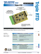
Analog Output Description
An optional single or dual analog output module is mounted on
the meter’s output carrier board.The single version is a single
channel, programmable, isolated 16-bit analog output that can
be scaled to any desired span within the full scale range of the
controller. It is user configured using a current / voltage selec-
tion header for either 0/4-20 mA or 0-10 V DC.
The dual version has two independently programmable, 16-bit
analog output channels with a common 0. They are hardware
configured for 10–0–10 V DC.Note, the analog output channels
of the dual version must not be confused with the four input
channels of the controller.
P
Use buttons
to set the zero setting
Calibration
Mode Analog Output 1
Analog Output 2
Use buttons
to set the full scale
setting
P
Use buttons
to set the calibration
low setting
Analog Output 1
Analog Output 2
Use buttons
to set the calibration
high setting
Scale Analog Output
Calibrate Analog Output
Main Programming Mode
Code 1
X
Analog Output 1
X
Analog Output 2
Select Analog Output Data Source
Use the
buttons to cycle
through the menu
[RESULT]
[CH1]
[CH2] [CH3] [CH4] [TOT_1] [TOT_2]
[PEAK]
[TARE]
[VALLEY]
[1 to 244]
Use the
buttons to select a
register (1 to 244)
as the data source
[DISP]
P
Controller
CH1
CH2
CH3
CH4
INPUTS
MAGNET 1
MAGNET 2
MAGNET 3
MAGNET 4
ANALOG OUTPUTS
Analog Output 1 (Single
or Dual Output Channel)
Analog Output 2 (Dual
Output Channel Only)
Like the single version, both analog outputs of the dual version
can be scaled to any desired span within the full scale range of
the controller.
The data source for the analog output can be selected from any
processed input signal, but is normally a magnet position or
velocity reading on one of the four input channels. The span
range of the analog output can be as small as 100 counts
between the low and high analog output signal.
P
P
Together x2
P
1st digit
Not Relevant 3rd digit selects
ASCII Mode for CH1
1st digit enters Calibration
Procedures mode 3rd digit selects
analog output
channel
2nd digit enters Calibrate Analog
Output mA/V (requires multimeter
connected to pins 16 and 17)
1st digit enters Related
Calibration Functions mode 3rd digit selects
analog output
channel
2nd digit enters Scale Analog
Output LOW / HIGH Display
Readings
For example, the data source for analog output 1 could be input
channel 3, while the data source for analog output 2 could be
input channel 1.
Once calibrated, the span range of the analog output can be
easily changed (rescaled) without having to recalibrate the out-
put.The low and high analog output signal values (mA or volts)
follow the new span range.
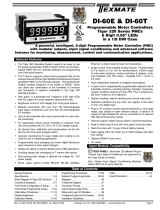
Analog Output Configuration
The single analog output version requires hardware and soft-
ware configuration, while the dual analog output version only
requires software configuration.
Hardware Configuration
On the single analog output version select the current or volt-
age position on the analog output selection header.
See Selection Header Positioning for a procedure.
Software Configuration
On the single and dual analog output versions the analog out-
put requires the following settings to be configured in the main
programming mode:
•Calibration Mode: Scale and calibrate the analog output.
•Code 1: Select the data source.
The calibration and data source settings are configured by set-
ting the three right-hand digits on the display to the settings
shown in the diagram below.
See Analog Output Procedures for a set of procedures to:
• Position the selection header (single analog output version only).
• Scale the analog output.
• Calibrate the analog output.
• Select the analog output data source.
2nd digit selects
Data Source mode

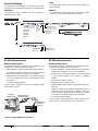
• BDD-652 Operator's Guide Page 7
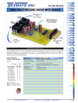
TOP VIEW
To open the rear cover,
use a small flat-blade
screwdriver. Press
down lightly to release
catch on top or bottom
of case and lever
outwards.
Rear
Cover
PART SIDE VIEW
To replace the rear cover, place the top
catches into their respective slots and
swing the bottom of the rear cover
towards the meter until the bottom
catches slide home. Press the rear
cover firmly into place.
Figure 1 – Rear Cover Removal
Top Catch
Bottom
Catch
ANALOG OUTPUT
SELECTION
CURRENT
VOLTAGE
Selection Header Positioning
STEP A Disconnect the Power Supply and Input/Output
Connectors
WARNING
AC and DC power supply voltages are
hazardous. Make sure the power supply
is isolated before disconnecting from
the meter.
1) Pull the AC power supply connector block
from the AC power input pins.
2) Pull all other input and output connectors
from their sockets.
STEP B Remove the Rear Cover from the Meter
1) Using a small flat-blade screwdriver, press
down lightly to release the catch on the top of
the case and gently lever outwards.
2) Repeat for the other top catch.
3) With both top catches free, pull the rear cover
away from the meter.
Analog Output
Selection Header
Output
Carrier
Board
Analog Output
Module (located
below Output
Carrier Board)
Figure 2 – Analog Output Selection Header Placement
STEP C Remove the Carrier Board
1) Pull the carrier board (top board) until it is
free from the meter case.
STEP D Select the Correct ANALOG OUTPUT SELEC-
TION HEADER Setting
1) If not in the correct position, pull the header
from its pins and reposition it to suit the ana-
log output signal:VOLTAGE or CURRENT.
STEP E Replace the Carrier Board
1) Gently push the carrier board back into the
meter case, taking care to correctly align the
board with the slots on the meter case.
STEP F Replace the Rear Cover
1) Place the top catches into their respective
slots and swing the bottom of the rear cover
towards the meter until the bottom catches
slide home.
2) Press the rear cover firmly into place.
STEP G Reconnect the Power Supply and Input/Output
Connectors
1) Ensure the power supply is still isolated.
2) Reconnect the AC power supply connector
block to the AC power input pins.
3) Reconnect the input and output connectors.
4) Remove the isolation from the power supply.
The power and input signal should be restored and the
meter should be in the operational display.
Top Catch
Note:
This procedure is only relevant to the single
analog output version.
Analog Output Procedures
The analog output selection header can be positioned for cur-
rent (0/4 to 20 mA) or voltage (0 to 10 VDC) output.To change
the header selection, the output carrier board must be removed
from the meter. See Figures 1 and 2.
To reposition the analog output selection header, proceed as
follows:

Page 8 • BDD-652 Operator's Guide
Analog Output Calibration Procedures Scaling the analog output requires the zero [ZERO] and full
scale [F_SCL] parameters to be set.
Zero is the setting at which the analog output is required to be
at its calibrated low output.Full scale is the setting at which the
analog output is required to be at its calibrated high output.
There are no limits to the difference between the zero and full
scale settings. The difference can be anywhere between 1
count and the entire display range of the meter.
Calibrating the analog output requires setting the [CAL_L] and
[CAL_H] parameters.[CAL_L] is used to set the calibrated low out-
put, and [CAL_H] is used to set the calibrated high output.The cal-
ibrated low and high outputs can be set anywhere between –0.3 to
+21 mA for current or –0.3 V to +10.5 V for voltage.
Example
In the following example procedure, we decribe how to calibrate
the analog output signal for 4 to 20 mA over the scaled range of
50 to 3000 counts.With a display of 50 counts, the analog out-
put must be 4.000 mA.With a display of 3000 counts, the ana-
log output must be 20 mA.
Steps 1 to 8 describe how to scale the analog output using the
[ZERO] and [F_SCL] settings, and Steps 9 to 19 describe how
to calibrate the analog output’s mA / V output using the [CAL_L]
and [CAL_H] settings.
Pin
16+
Pin
17–
SP1 SP2 SP3 SP4 SP5 SP6
F2
P
F1
MULTIMETER
V
V
mV
mA
A
OFF
µA
COM V Ω
mA µA
A
PEAK MIN MAX
MIN MAX RANGE HOLD
Hz
REL
Ω
Ω
–
+
SP1 SP2 SP3 SP4 SP5 SP6
F2
P
F1
SP1 SP2 SP3 SP4 SP5 SP6
F2
P
F1
To
Step
5
From Step 4
Press
at same
time
Press
at same
time
Step 1
Step 2
Step 3
Step 4
Step 5
Step 6
Step 7
Step 8
Enter Brightness
Mode
Pass Brightness Mode
and enter Calibration
Mode
Operational Display
Enter [ZERO]
setting mode
Adjust the display to 0.0
low analog output
signal counts
Example
Set CAL to [251]:
1st Digit = 2 Selects Related
Calibration Functions
2nd Digit = 5 Selects Scale Analog Output
3rd Digit = 1 Select Analog Output 1 for
Scaling
0 –
1 Analog Output 1
2 Analog Output 2
3 –
4 –
Adjust the display to 500.0
high analog output
signal counts
Save scale settings (zero
and full scale). To return
directly to the Operational
Display, proceed to Step 17.
Calibrate the Analog Output Signal
continued on next page (Step 9).
Enter the [F_SCL]
Setting mode
Note:
The scale settings
may be changed at
any time without
having to recalibrate
the analog mA / V
output signal.
SP1 SP2 SP3 SP4 SP5 SP6
F2
P
F1
Press
1
SP1 SP2 SP3 SP4 SP5 SP6
F2
P
F1
SP1 SP2 SP3 SP4 SP5 SP6
F2
P
F1
SP1 SP2 SP3 SP4 SP5 SP6
F2
P
F1
SP1 SP2 SP3 SP4 SP5 SP6
F2
P
F1
OR
SP1 SP2 SP3 SP4 SP5 SP6
F2
P
F1
Press
1
OR
SP1 SP2 SP3 SP4 SP5 SP6
F2
P
F1
Press
1
SP1 SP2 SP3 SP4 SP5 SP6
F2
P
F1
SP1 SP2 SP3 SP4 SP5 SP6
F2
P
F1
OR
SP1 SP2 SP3 SP4 SP5 SP6
F2
P
F1
Press
1
Figure 3 – Multimeter to Meter Connections
Calibration Setup Procedure
The calibration procedure is in two parts: scaling the low and
high display settings and then calibrating the mA / V output.
Scaling can be changed independently of calibration and vice
versa.
1) See Figure 2. Make sure the ANALOG OUTPUT SELECTION
HEADER on the analog output module is set in the appropriate
position:VOLTAGE or CURRENT.
2) See Figure 3. Connect a multimeter to the analog output con-
nector at the rear of the meter (pin 16-positive, pin 17-negative).
3) Make sure the multimeter is set to read the appropriate signal
type: volts or milliamps.
Scale Analog Output
ST
STAR
ART HERE
T HERE

• BDD-652 Operator's Guide Page 9
X
Ensure the low
analog output
signal reading
[CAL] on the
multimeter display
is 4.00 mA.
If not 20 mA,
press the
or button on
the BDD 652
until the reading
on the
multimeter
display is
correct.
To Step
14
From Step 13
Step 9
Step 10
Step 11
Set CAL to [15X]:
1st Digit = 1 Selects Calibration Procedures
2nd Digit = 5 Selects Calibrate Analog Output
3rd Digit = 1 Select Analog Output 1 for Scaling
as per Step 3
Step 18
Step 19
Save calibration mode
[000] setting and enter
Code 1
Exit Code 1 and return
to operational display
Enter analog output
low signal calibration
mode
Step 13
Step 16
Save the low analog output
signal setting. Enter analog
output high signal calibration
mode
Step 17
Step 14
Step 15
Ensure the high
analog output
signal reading
[CAL_HI] on the
multimeter
display is 20 mA.
Reset calibration
mode setting
to [000]
Return to the
calibration mode
[CAL] menu
Configure Analog Output Procedure
continued from bottom of previous page
0 –
1 Analog Output 1
2 Analog Output 2
3 –
4 –
SP1 SP2 SP3 SP4 SP5 SP6
F2
P
F1
SP1 SP2 SP3 SP4 SP5 SP6
F2
P
F1
OR
SP1 SP2 SP3 SP4 SP5 SP6
F2
P
F1
Press
1
SP1 SP2 SP3 SP4 SP5 SP6
F2
P
F1
SP1 SP2 SP3 SP4 SP5 SP6
F2
P
F1
SP1 SP2 SP3 SP4 SP5 SP6
F2
P
F1
SP1 SP2 SP3 SP4 SP5 SP6
F2
P
F1
If not correct, press
the OR
button on the BDD
652 until the
reading on the
multimeter display
is correct.
Step 12
SP1 SP2 SP3 SP4 SP5 SP6
F2
P
F1
SP1 SP2 SP3 SP4 SP5 SP6
F2
P
F1
OR
X
SP1 SP2 SP3 SP4 SP5 SP6
F2
P
F1
SP1 SP2 SP3 SP4 SP5 SP6
F2
P
F1
SP1 SP2 SP3 SP4 SP5 SP6
F2
P
F1
SP1 SP2 SP3 SP4 SP5 SP6
F2
P
F1
Operational Display
Press
1
Press
at same
time
Press
at same
time
Pin
16+
Pin
17–
SP1 SP2 SP3 SP4 SP5 SP6
F2
P
F1
OR
Example
MULTIMETER
V
V
mV
mA
A
OFF
µA
COM V Ω
mA µA
A
PEAK MIN MAX
MIN MAX RANGE HOLD
Hz
REL
Ω
Ω
–
+
Example
SP1 SP2 SP3 SP4 SP5 SP6
F2
P
F1
Press
1Pin
17–Pin
16+
MULTIMETER
V
V
mV
mA
A
OFF
µA
COM V Ω
mA µA
A
PEAK MIN MAX
MIN MAX RANGE HOLD
Hz
REL
Ω
Ω
–
+
Pin
17–Pin
16+
Example
MULTIMETER
V
V
mV
mA
A
OFF
µA
COM V Ω
mA µA
A
PEAK MIN MAX
MIN MAX RANGE HOLD
Hz
REL
Ω
Ω
–
+
SP1 SP2 SP3 SP4 SP5 SP6
F2
P
F1
OR
X
SP1 SP2 SP3 SP4 SP5 SP6
F2
P
F1
Press
1
Pin
17–Pin
16+
MULTIMETER
V
V
mV
mA
A
OFF
µA
COM V Ω
mA µA
A
PEAK MIN MAX
MIN MAX RANGE HOLD
Hz
REL
Ω
Ω
–
+
Calibrate Analog Milliamp/Voltage Output Signal

Page 10 • BDD-652 Operator's Guide
Step 1
Step 2
Step 3
Example
Step 4
Step 6
0 Primary Display
1 Second Display
2 Third Display
3 Peak/Valley
4 Analog Output 1
5 Analog Output 2
6 Totalizer 1
7 Totalizer 2
Step 7
Step 8
Step 9
From Step 5
Step 5
Select [CH1] as the Data Source for
Analog Output 1 from the options listed
in the Select Data Source diagram below.
Set Code 1 to [X54]:
1st Digit = X Not relevant
2nd Digit = 5 Selects data source mode
3rd Digit = 4 Selects analog output 1
Select [000] to leave
Code 1
Save Data Source
setting. Enter Code 2
Exit Code 2. Return to
Operational Display
Enter Brightness
Mode
Pass Brightness and
Calibration Modes
and enter Code 1
SP1 SP2 SP3 SP4 SP5 SP6
F2
P
F1
SP1 SP2 SP3 SP4 SP5 SP6
F2
P
F1
SP1 SP2 SP3 SP4 SP5 SP6
F2
P
F1
Operational Display
Press
at same
time
Press
at same
time
SP1 SP2 SP3 SP4 SP5 SP6
F2
P
F1
SP1 SP2 SP3 SP4 SP5 SP6
F2
P
F1
Press
at same
time
Press
at same
time
Operational Display
SP1 SP2 SP3 SP4 SP5 SP6
F2
P
F1
Press
2
SP1 SP2 SP3 SP4 SP5 SP6
F2
P
F1
SP1 SP2 SP3 SP4 SP5 SP6
F2
P
F1
SP1 SP2 SP3 SP4 SP5 SP6
F2
P
F1
OR
X
Press
1
SP1 SP2 SP3 SP4 SP5 SP6
F2
P
F1
SP1 SP2 SP3 SP4 SP5 SP6
F2
P
F1
SP1 SP2 SP3 SP4 SP5 SP6
F2
P
F1
Press
1
SP1 SP2 SP3 SP4 SP5 SP6
F2
P
F1
SP1 SP2 SP3 SP4 SP5 SP6
F2
P
F1
OR
X
SP1 SP2 SP3 SP4 SP5 SP6
F2
P
F1
Press
1
Enter the Data
Source mode
OR
Return to Code 1
Example Procedure:
Configure Analog Output 1 with channel 1 [CH1] as the data
source by setting Code 1 to [X54]. See diagram below for data
source selection options.
Select Data Source
Programming Tips for all Configuration Programming
To enter the main programming mode press the and buttons at the same
time.To exit and return to the operational display, press the and buttons again
at the same time.(See also note below at Step 9).
At the end of any procedure (Step 8 in this procedure) the button must be
pressed before the and buttons are pressed, otherwise the meter returns to
the operational display without saving the new settings.
P
P
P
P
Select the Data Source for the Analog Output
The following example procedure decribes how to select the
data source for analog output 1.
ST
STAR
ART HERE
T HERE
Use the
buttons to cycle
through the menu
[RESULT]
[CH1] [CH2] [CH3] [CH4] [TOT_1] [TOT_2] [PEAK]
[TARE]
[VALLEY]
[1 to 244] Use the
buttons to select a
register (1 to 244)
as the data source
[DISP]
P

• BDD-652 Operator's Guide Page 11
Serial Port Description
Communication with the controller is available via the serial port
using either isolated RS-232 or RS-485 in ASCII mode format.
Using the serial port requires the controller to be set in the
ASCII mode in Code 3 of the main programming mode.
What is the ASCII Mode?
The ASCII mode is a simple isolated ASCII communication
protocol using the standard ASCII character set.This mode pro-
vides external communication between the controller and a PC
allowing remote programming to be carried out.
BDD-652 controllers use a serial communication channel to
transfer data from the controller to another device. With serial
communications, data is sent one bit at a time over a single
communications line. The voltage is switched between a high
and low level at a predetermined transmission speed (baud
rate) using ASCII encoding. Each ASCII character is transmit-
ted individually as a byte of information (eight bits) with a vari-
able idle period between characters.The idle period is the time
between the receiving device receiving the stop bit of the last
byte sent and the start bit of the next byte.The receiving device
(for example a PC) reads the voltage levels at the same inter-
val and then translates the switched levels back to an ASCII
character. The voltage levels depend on the interface standard
being used.
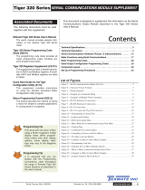
Table 1 lists the voltage level conventions used for RS-232 and
RS-485.The voltage levels listed are at the receiver.
1elbaT snoitnevnoCleveLegatloVecafretnI
cigoLetatSecafretnI232-SR584-SR
1)eldi(kraMV51-ot3-:DXR,DXTVm002-<b+a
0)evitca(ecapSV51+ot3+:DXR,DXTVm002+>b-a
Character Frame Formats
Each ASCII character is 'framed' with:
•A start bit.
•An optional error detection parity bit.
•And one or more ending stop bits.
For communication to take place, the data format and baud rate
(transmission speed) must match that of the other equipment in
the communication circuit. Figure 4 shows the character frame
formats used by the meter.
Idle 0b
0b1b2b3b4b5b6Idle
8 data, no parity, 1 stop
Idle 0b
0b1b2b3b4b5b6PIdle
1
8 data, parity, 1 stop
Note: b0 to b7 is ASCII data.
Start
Bit Stop
Bit
1
Receiving Device (PC)
Sending Device (Meter)
Data Bits
b7
b7
Stop
Bit
Parity
Bit
Figure 4 – Character Frame Formats
2elbaT sretsigeRtib-23IICSAnommoC
#N.geRIICSAnoitcnuF
1sutatSmralA
2retsigeRyalpsiD
3tluseRataDdessecorP
41lennahC–ataDdessecorP
52lennahC–ataDdessecorP
93 3lennahC–ataDdessecorP
04 4lennahC–ataDdessecorP
61tniopteS
72tniopteS
83tniopteS
94tniopteS
01 5tniopteS
11 6tniopteS
21 kaeP
31 yellaV
41 eraT
51 esUerutuFrofdevreseR
61 1latoT
71 2latoT
Start Bit and Data Bits
Data transmission always begins with the start bit.The start bit
signals the receiving device to prepare to receive data. One bit
period later, the least significant bit of the ASCII encoded char-
acter is transmitted, followed by the remaining data bits. The
receiving device then reads each bit position as they are trans-
mitted and, since the sending and receiving devices operate at
the same transmission speed (baud rate), the data is read with-
out timing errors.
Parity Bit
To prevent errors in communication, the sum of data bits in
each character (byte) must be the same: either an odd amount
or an even amount.The parity bit is used to maintain this simi-
larity for all characters throughout the transmission.
It is necessary for the parity protocol of the sending and receiv-
ing devices to be set before transmission. There are three
options for the parity bit, it can be set to either:
•None – which means there is no parity.
•Odd – which means the sum of bits in each byte is odd.
•Even – which means the sum of bits in each byte is even.
After the start and data bits of the byte have been sent, the par-
ity bit is sent. The transmitter sets the parity bit to 1 or 0 mak-
ing the sum of the bits of the first character odd or even,
depending on the parity protocol set for the sending and receiv-
ing devices.
As each subsequent character in the transmission is sent, the
transmitter sets the parity bit to a 1 or a 0 so that the protocol
of each character is the same as the first character: odd or
even.
Table 2 provides a list of the most commonly accessed ASCII
mode registers in the controller.

Page 12 • BDD-652 Operator's Guide
The parity bit is used by the receiver to detect errors that may
occur to an odd number of bits in the transmission. However, a
single parity bit cannot detect errors that may occur to an even
number of bits. Given this limitation, the parity bit is often
ignored by the receiving device. The user sets the parity bit of
incoming data and sets the parity bit to odd, even or none (mark
parity) for outgoing data.
Parity is set in the Calibration Mode.
Stop Bit
The stop bit is the last character to be transmitted.The stop bit
provides a single bit period pause to allow the receiver to pre-
pare to re-synchronize to the start of a new transmission (start
bit of next byte). The receiver then continuously looks for the
occurrence of the start bit.
Note:
BDD-6520 controllers use only one stop bit.
Command Response Time
The controller uses half-duplex operation to send and receive
data. This means that it can only send or receive data at any
given time. It cannot do both simultaneously. The controller
ignores commands while transmitting data, using RXD as a
busy signal.
When the controller receives commands and data, after the
first command string has been received, timing restrictions are
imposed on subsequent commands. This allows enough time
for the controller to process the command and prepare for the
next command.
See Figure 5. At the start of the time interval t1, the sending
device (PC) prints or writes the string to the com port, thus ini-
tiating a transmission. During t1 the command characters are
under transmission and at the end of this period the command
terminating character is received by the controller. The time
duration of time interval t1is dependent on the number of char-
acters and baud rate of the channel:
t1= (10 * # of characters) / baud rate
At the start of time interval t2, the controller starts to interpret
the command, and when complete, performs the command
function.
After receiving a valid command string, the controller always
indicates to the sending device when it is ready to accept a new
command. After a read command, the controller responds with
the requested data followed by a carriage return (øDH) and a
line feed (øAH) character.After receiving a write command, the
controller executes the write command and then responds with
a carriage return/line feed.
The sending device should wait for the carriage return/line feed
characters before sending the next command to the controller.
If the controller is to reply with data, time interval t2is controlled
by using the command terminating character: $or *.The $ter-
minating character results in a response time window of 50 ms
minimum and 100 ms maximum. This allows enough time to
release the sending driver on the RS-485 bus.Terminating the
command line with the *symbol, results in a response time
window (t2) of 2 ms minimum and 50 ms maximum.The faster
response time of this terminating character requires that send-
ing drivers release within 2 ms after the terminating character
is received.
At the start of time interval t3, the meter responds with the first
character of the reply. As with t1, the time duration of t3is
dependent on the number of characters and baud rate of the
channel:
t3= (10 * # of characters) / baud rate
At the end of t3the meter is ready to receive the next command.
The maximum throughput of the meter is limited to the sum of
the times: t1, t2, t3.
Ready t1
Response From The Meter
Command
Terminator
Received
t2
First
Character
of Reply
Ready
t3
Reply
Transmission
Time
Figure 5 – Timing Diagram
ASCII Serial Mode Read/ Write Information
ASCII Command Character Descriptions
Table 3 (see next page) describes the functions of the com-
mand string characters. Table 4 shows examples of how the
command string is constructed.
4elbaT selpmaxEgnirtSdnammoCIICSA
gnirtSdnammoC noitpircseDgnirtSdnammoC
$RS .dnopsersretemlla,yaledsm05,eulavyalpsiddaeR
$r51s .sdnopser51sserddaretem,yaledsm05,eulavyalpsiddaeR
*21RS .dnopsersretemlla,yaledsm2,eulavkaepdaeR
*031rS .dnopsersretemlla,yaledsm2,gnittes1edoCdaeR
$00001-2w2s .yaledsm05,2sserddaretemforetsigeryalpsidehtot00001etirW
$1_nahCTWS gnirtstxetIICSAetirW 1_nahC .sm05,Tretsigertxetot
*7,841w01S .yaledsm2,01sserddaretemno7otssenthgirbegnahC
Command String Construction
When sending commands to the BDD-652 using a Terminal
emulation program, a string containing at least one command
character must be constructed. A command string consists of
the following characters and must be constructed in the order
shown:
1) A start character.
2) The meter (node) address (optional).
3) The read/write command.
4) The register address.
5) A separator character.
6) The data value.
7) The message terminator.
Figure 6 shows an example of a command string.

• BDD-652 Operator's Guide Page 13
3elbaT snoitpircseDretcarahCdnammoC
dnammoCnoitpircseD noitcnuF
Sro stratS retcarahC ehT retcarahctrats .gnirtsehtniretcarahctsrifehtebtsum
0ot 552 )edoN(reteM sserddA reificepS
siretcarahctratsehtgniwollofretcarahcehtfI.retemcificepsaotsserddanasngissaretcarahctxenehT .demussasi0sserddaneht,rebmunIICSAnaton
.0sserddaotdnopsersretemllA
Rro rrof
daer
Wro wrof
etirw
etirW/daeR dnammoC ehtsiretcarahctxenehT dnammocetirw/daer .retcarahc
ehT dnammocdaer .retemehtmorfretsigerasdaer
ehT dnammocetirw .retemehtforetsigeraotsetirw
noitarepoehttroballiwretcarahcetirwrodaerehtrofretcarahcrehtoynagnisU
IICSA rebmun 1ot
53556
retsigeR sserddA ehT sserddaretsiger morfrebmunIICSAnaebrehtienactI.txendeificepssinoitarepoetirw/daerehtrof .)evitisnesesacton(RotAmorfrettelIICSAnagniretneybdesseccaebnac81ot1retsigerro53556ot1
eulavatadehthtiwdnopsersyawlalliwretemeht,dnammocdaeranidettimosiretcarahcsserddaehtfI .yalpsidehtnoyltnerruc
.dnammocetirwarofdeificepsebtsumsserddaretsigerehT
ecapS ro
"", rotarapeS retcarahC IICSAnanahtrehtognihtemosebtsumretcarahctxeneht,dnammocetirwanisserddaretsigerehtretfA aebnactI.eulavatadehtmorfsserddaretsigerehtetarapesotdesusisihT.rebmun ecaps "aro ", ynaro
"atpecxeretcarahcrehto $"aro" *."
egnaR neewteb 9999999–
ot 9999999
eulaVataDeht,retcarahcrotarapesehtretfA eulavatad foegnarehtnirebmunIICSAnaebtsumtI.tnessi 9999999–
ot 9999999 .)retsigeRtnioPdexiF(
.desseccasiretsigerhcihwnognidnepedyravlliwegnarehT:etoN
$ro *egasseM rotanimreT ehtsiegassemehtniretcarahctsalehT rotanimretegassem rehtieebtsumsihT. $ro *.
ehtfI $.tnessiylperaerofebdetresnisism05foyaledmuminima,rotanimretasadesusi
ehtfI *.tnessiylperaerofebdetresnisism2foyaledmuminima,rotanimretasadesusi
ehT $dna *.gnirtsegassemehtniesleerehwynaraeppatontsumsretcarahc
FL/RC reteM esnopseR agnidnesybsdnopserti,noitcurtsnietirwrodaeradetelpmocsahretemehtretfA deefenil/nruteregeirrac IICSAehtniretcarahctsalehtswollofFL/RCeht,dnammocdaerasawnoitcurtsniehtfI.tsohehtotkcab roftiawtsumtsohehT.tsohehtotkcabtnesesnopserylnoehtsiFL/RCeht,dnammocetirwasawtifI.gnirts .retemehtotsdnammocrehtrufynagnidneserofebsiht
.FL/RCaybdewollofretcarahcllunasecudorp,retsigertnatsixe-nonrodilavtonaotetirwrodaerA
Multiple Write
The multiple write feature of the BDD-652 allows multiple regis-
ters to be written to in a single ASCII command string.It is sim-
ilar to a normal write command but with the following differ-
ences:
•After the first data value, a separator character is inserted
instead of the message terminator.The next register address is
then specified, followed by another separator character and the
next data value.This procedure is repeated for each new regis-
ter.The message terminator is added after the last data value in
the string.
•Any number of registers can be written to using the multiple
write feature, as long as the total length of the command string
does not exceed 73 ASCII characters, including spaces and the
message terminator.
Figure 7 shows two examples of the multiple write command.
Note:
The multiple write feature cannot be used with spe-
cial ASCII registers (H to X).
Start
Character Meter
Address Read/Write
Command Register
Address Separator
Character Data
Value Message
Terminator
SW6,10000,7,20000,8,30000$
Start
Character Meter
Address Read/Write
Command Register
Address Separator
Character Data
Value Message
Terminator
Start
Character Meter
Address Read/Write
Command Register
Address Separator
Character Data
Value Message
Terminator
S6wL -32766 M 32766*
Figure 7 – Examples of Multiple Write Command
Start
Character Meter
Address Read/Write
Command Register
Address Separator
Character Data
Value Message
Terminator
Sr130*
Figure 6 – Example of a Command String

Page 14 • BDD-652 Operator's Guide
Use buttons
to set baud rate Use buttons
to set parity
Use buttons
to set address
Calibration
Mode
X
Set Serial Port Settings
Main Programming Mode
Serial Port Settings
The following serial port settings are configured in the calibra-
tion mode of the main programming mode (see diagram below).
Baud Rate
The baud rate range is selectable from 300 to 19200. The
default baud rate is 9600.
Parity
The default parity setting is [oFF]. Parity [odd] or [EVEn] can
also be selected.
Address
For RS-485 serial communications the default address setting
is 1, but can be set to anywhere between 1 and 255.
PP
P
Code 3
XX
Select ASCII Mode for CH1
P
3rd digit Selects
ASCII Mode for CH1
P
Together x2 Use buttons to select
the relevant output channel
to apply serial port settings:
[200] = Result
[201] = CH1
[202] = CH2
[203] = CH3
[204] = CH4
P
x2
Rear of TD6500
PC Running
Terminal Program
4-wire Telephone
Cable with RJ-11
Connectors
30 29 28 27 26 25 24 23 17 16
14 158910 11
Input Module
(See specific input module data
sheet for connection details)
123456
21 20 19 18
DB-9 Female to RJ-11
Interface Connector
RS-232 Interconnections
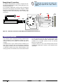
Hardware Requirements
The following hardware is required to set the BDD-652 up for
simple RS-232 communications (see Figure 7):
•BDD-6520 with RS-232 serial output module option installed.
•RJ-11 to DB-25 interface connector (and possibly a DB-25 to
DB-9 interface connector depending on PC serial port).
•Standard 4-wire cable with male RJ-11 connectors (see Figure
9 and 10, and Tables 5 and 6 for a wiring diagram and pin
descriptions).
•PC running a terminal program.
Figure 8 shows a simple RS-232 connection between a BDD-
652 controller and a PC.
Figure 8 – RS-232 Hardware Connections
RS-485 Interconnections
Hardware Requirements
The following hardware is required to set the BDD-652 up for
simple RS-485 communications (see Figure 9):
•A number of BDD-652 controllers with an RS-485 serial output
module option installed (this can be up to 64 controllers).
•A number of RJ-11 dual outlet adapters to connect the meters
in series (amount depends on the number of controllers
installed).
•RJ-11 to DB-25 interface connector.
•Isolated converter (RS-485 to RS-232)
•Possibly a DB-25 to DB-9 interface connector depending on PC
serial port.
•Lengths of standard 2-wire telephone cable with male RJ-11
connectors (enough to connect the controllers in series and
connect to the RJ-11 to DB-25 interface connector).See Figure
10 and Table 5 for a wiring diagram and pin descriptions.
•PC running a terminal program.
Figure 8 shows a number of BDD-652 controllers with the hard-
ware required to connect directly to a PC using RS-485.
3rd digit selects the rel-
evant output channel to
apply serial port settings
2nd digit selects Serial
Communications
Properties mode
1st digit
enters
Related
Calibration
Functions
mode
1st & 2nd digit
Not Relevant
P

• BDD-652 Operator's Guide Page 15
Note:
In theory, up to 64 con-
trollers can be connected
together. The controllers
can be connected togeth-
er in series or parallel
using RJ-11 type con-
necters or hardwiring
(each BDD-652 can only
be hardwired if it has a
screw terminal instead of
an RJ-11 connecter).
Figure 7 has the con-
trollers connected in
series using RJ-11 type
connecters.
RJ-11
Socket
Isolated
GND
RXD
TXD
Reserved
Optional
+5 VDC
Reserved
See Table 5 for
TD6500 pin numbers
Figure 11 – RJ-11 to 9-pin and 25-pin
D Connectors
Table 5 lists the pinouts for an RS-
232 or RS-485 to RJ-11 socket con-
figuration.
5elbaT )tekcoS11-JR(stuoniPnoitacinummoClaireS
.oNniP232-SR584-SR
91 esuerutufrofdevreseResuerutufrofdevreseR
02 laireSdevieceR.DXR)woL(B
12 laireSdettimsnarT.DXT)hgiH(A
22 rewopotCDV5+lanoitpO sretrevnoclanretxe 584-SRro232-SRnorepmuj( )deredlosebtsumsdraob
rewopotCDV5+lanoitpO sretrevnoclanretxe 584-SRro232-SRnorepmuj( )deredlosebtsumsdraob
32 dnuorGdetalosIdnuorGdetalosI
42 esuerutufrofdevreseResuerutufrofdevreseR
14
1
15
2
16
3
17
4
18
5
19
6
20
7
21
8
22
9
23
10
24
11
25
12
13
6
1
7
2
8
3
9
4
5
25-Pin D Connector
(See Table 6 for pin descriptions)
(Viewed from the pin side of a female connector)
9-Pin D Connector
(See Table 6 for pin descriptions)
(Viewed from the pin side of a
female connector)
RJ-11
Connector
Socket
Isolated
GND
RXD
TXD
Reserved
Optional
+5 VDC
Reserved
Isolated
GND
RXD
TXD
Reserved
Optional
+5 VDC
Reserved
RJ-11
Connector
Socket
Figure 10 – RJ-11 Connections
Table 6 lists the pinouts
for an RS-232 to 9-pin or
25-pin D connector.
6elbaT srotcennoCDniP-9&niP-52ot232-SR
niP-52emaNniPniP-9
1dnuorGemarF -
2ataDtimsnarT 3
3ataDevieceR 2
4dneSottseuqeR 7
5dneSotraelC 8
6ydaeRteSataD 6
7dnuorGlangiS 5
8tceteDreirraCataD 1
9devreseR -
01 devreseR -
11 dengissanU -
21 tceteDreirraC.ceS -
31 dneSreirraC.ceS -
41 ataDtimsnarT.ceS -
51 kcolCrettimsnarT -
61 ataDevieceR.ceS -
71 kcolCrevieceR -
81 kcabpooLlacoL -
91 dneSottseuqeR.ceS -
02 ydaeRlanimreTataD 4
12 tceteDytilauQlangiS/kcabpooLetomeR
22 rotacidnIgniR 9
32 tceleSetaRataD -
42 kcolCrettimsnarT -
52 edoMtseT -
Figure 9 – RS-485 Hardware Connections
DB-25 Female to RJ-11
Interface Connector
Rear of BDD-652
PC Running
Terminal Program
2-wire Cable
with RJ-11
Connectors
Rear of BDD-652 Rear of BDD-652 Rear of BDD-652
Isolated Converter
(DB-25 Male to
DB-25 Female)
DB-25 Male to
DB-9 Female
Interface Connector
DB-9 Female
Connector to
PC Serial Port
Up to 64 meters
can be connected
30 29 28 27 26 25 24 23 17 16
14 158 910 11
Input Module
(See specific input module data
sheet for connection details)
123456
30 29 28 27 26 25 24 23 17 16
14 158910 11
Input Module
(See specific input module data
sheet for connection details)
123456
RJ-11 Dual
Outlet Adapter
30 29 28 27 26 25 24 23 17 16
14 158910 11
Input Module
(See specific input module data
sheet for connection details)
123456
RJ-11 Dual
Outlet Adapter
30 29 28 27 26 25 24 23 17 16
14 158910 11
Input Module
(See specific input module data
sheet for connection details)
123456
RJ-11 Dual
Outlet Adapter

Page 16 • BDD-652 Operator's Guide
Setup RS-232 Interface
Carry out the following procedures to establish communications
between the BDD-652 and a PC using RS-232 interface:
See Figures 8, 9, 10, 11 and Tables 5 and 6.
STEP A Connect the Meter to the PC
1) Connect one end of the standard 4-wire tele-
phone cable to the RJ-11 serial output port on
the BDD-652.
2) Connect the other end of the standard 4-wire
telephone cable to the RJ-11 to DB-25 inter-
face connector.
3) Connect the DB-25 interface connector to the
serial port of the PC.
STEP B Make Sure the PC and BDD-652 are Powered
Up
1) Make sure the BDD-652 is powered up.
2) Make sure the PC is powered up.
STEP C Check Communication Between the PC and the
BDD-652
1) Make sure the terminal program is running.
2) Check that communication is established
between the BDD-652 and the PC:
Write SR* in the terminal program.
The screen displays the current meter reading.
Setup RS-485 Interface
Carry out the following procedures to establish communications
between a number of meter sand a PC using RS-485 interface:
See Figures 8, 9, 10, 11 and Tables 5 and 6.
STEP A Connect the BDD-652 Controllers Together
1) Connect the controllers together using the 2-
wire telephone cables as shown in Figure 8.
STEP B Connect the Meter to the Isolated Converter
1) Connect one end of the standard 2-wire tele-
phone cable to the RJ-11 serial output port on
the first BDD-652.
2) Connect the other end of the standard 2-wire
telephone cable to the RJ-11 to female DB-25
interface connector.
3) Connect the RJ-11 to female DB-25 interface
connector to the end of the isolated convertor
marked: LOGIC OUTPUT FROM METER.
4) Connect the isolated converter to the DB-25 to
DB-9 interface connector.
5) Connect the DB-9 end of the DB-25 to DB-9
interface connector to the serial port of the PC.
STEP C Check Communication Between the PC and the
BDD-652
1) Make sure the terminal program is running.
2) Check that communication is established
between the BDD-652 and the PC:
Write SR* in the terminal program.
The screen displays the current BDD-652 read-
ing.
Configure Serial Port Settings
See procedure diagram on Pages 17 and 18.
Select ASCII Mode
See procedure diagram on Page 18.
Serial Port Procedures
Programming Tip
When configured in the ASCII mode (Code 3 set to XX0), the serial port set-
tings do not require a time delay to be set.When configuring the serial port
settings in the calibration mode [CAL][20X] the time delay mode does not
appear in the menu.
The ASCII Mode uses the terminating characters with built-in time delays:
$= 50 milliseconds
*= 2 milliseconds

• BDD-652 Operator's Guide Page 17
X
Step 1
Step 2
Step 3
Step 4
Step 5
Set Calibration Mode to [20X]:
1st Digit = 2 Selects Related Calibration
Functions
2nd Digit = 0 Selects Serial
Comms. Properties
3rd Digit = X Select relevant
channel
Enter Brightness
Mode
Pass Brightness, enter
Calibration Mode
Set the baud rate
to [2400]
Example
Enter CAL
and select
channel CH1.
Step 6
Save the baud rate.
Enter the Parity
setting menu
Enter the Baud Rate
setting menu
Example
Set parity
to [ODD]
Save the parity setting.
Enter the Time Delay
setting mode
Example
Step 7
Step 8
Step 9
Note, the time delay
setting is not relevant to
serial port settings when
the TD6500 is setup for
the ASCII mode in Code 3
Select an Address
setting
Step 10
Step 11
Save the address
setting. Return to the
Calibration Mode [CAL]
Example
Step 12
To
Step 9
From Step 8
SP1 SP2 SP3 SP4 SP5 SP6
F2
P
F1
SP1 SP2 SP3 SP4 SP5 SP6
F2
P
F1
Press
at same
time
Press
at same
time
Operational Display
SP1 SP2 SP3 SP4 SP5 SP6
F2
P
F1
Press
1
SP1 SP2 SP3 SP4 SP5 SP6
F2
P
F1
SP1 SP2 SP3 SP4 SP5 SP6
F2
P
F1
SP1 SP2 SP3 SP4 SP5 SP6
F2
P
F1
OR
Press
1
SP1 SP2 SP3 SP4 SP5 SP6
F2
P
F1
SP1 SP2 SP3 SP4 SP5 SP6
F2
P
F1
OR
SP1 SP2 SP3 SP4 SP5 SP6
F2
P
F1
Press
1
SP1 SP2 SP3 SP4 SP5 SP6
F2
P
F1
SP1 SP2 SP3 SP4 SP5 SP6
F2
P
F1
OR
SP1 SP2 SP3 SP4 SP5 SP6
F2
P
F1
Press
1
SP1 SP2 SP3 SP4 SP5 SP6
F2
P
F1
SP1 SP2 SP3 SP4 SP5 SP6
F2
P
F1
Press
1
SP1 SP2 SP3 SP4 SP5 SP6
F2
P
F1
SP1 SP2 SP3 SP4 SP5 SP6
F2
P
F1
OR
SP1 SP2 SP3 SP4 SP5 SP6
F2
P
F1
Pass thru the Time Delay
setting mode.
Enter the Address
setting mode
Press
1
SP1 SP2 SP3 SP4 SP5 SP6
F2
P
F1
SP1 SP2 SP3 SP4 SP5 SP6
F2
P
F1
SP1 SP2 SP3 SP4 SP5 SP6
F2
P
F1
OR
X
SP1 SP2 SP3 SP4 SP5 SP6
F2
P
F1
SP1 SP2 SP3 SP4 SP5 SP6
F2
P
F1
Step 14
Save Calibration Mode
[XX0] setting and enter
Code 1
Exit Code 1 and return
to Operational Display
Step 13
Reset Calibration
Mode setting
to [XX0]
X
SP1 SP2 SP3 SP4 SP5 SP6
F2
P
F1
Operational Display
Press
at same
time
Press
at same
time
ST
STAR
ART HERE
T HERE
Configure Serial Port Settings

Page 18 • BDD-652 Operator's Guide
X
Step 1
Step 2
Step 3
Step 4
Step 5
Set Code 3 to [XX0]:
1st Digit = X Not relevant
2nd Digit = X Not relevant
3rd Digit = 0 Selects ASCII Mode
Enter Brightness Mode
Pass Brightness thru
to Code 2 and enter
Code 3
Save Code 3
settings
Exit Code 4
and return to
Operational Display
X
SP1 SP2 SP3 SP4 SP5 SP6
F2
P
F1
SP1 SP2 SP3 SP4 SP5 SP6
F2
P
F1
Press
at same
time
Press
at same
time
Operational Display
SP1 SP2 SP3 SP4 SP5 SP6
F2
P
F1
Press
1
SP1 SP2 SP3 SP4 SP5 SP6
F2
P
F1
SP1 SP2 SP3 SP4 SP5 SP6
F2
P
F1
SP1 SP2 SP3 SP4 SP5 SP6
F2
P
F1
OR
Press
1
SP1 SP2 SP3 SP4 SP5 SP6
F2
P
F1
SP1 SP2 SP3 SP4 SP5 SP6
F2
P
F1
X
X
SP1 SP2 SP3 SP4 SP5 SP6
F2
P
F1
Operational Display
Press
at same
time
Press
at same
time
0 ASCII Mode
1 Modbus Mode
2 Master Mode
3 PRINT Mode
4 Ethernet Mode
5 DeviceNet Mode
Select ASCII Mode
ST
STAR
ART HERE
T HERE

• BDD-652 Operator's Guide Page 19
Channel 1 data. 32-bit register holds the
processed data for channel 1. 253CH1
Channel 2 data. 32-bit register holds the
processed data for channel 2. 252CH2
Channel 3 data. 32-bit register holds the
processed data for channel 3. 251CH3
Channel 4 data. 32-bit register holds the
processed data for channel 4. 250CH4
Result data. 32-bit register holds the processed
data for result channel. 254RESULT
Magnet 1 position
Magnet 2 position
Magnet 3 position
Magnet 4 position
Magnet 2 position minus mag-
net 1 position
87VARIABLE4 Macro variable 4. 32-bit register used by the
macro for variable space.
Magnet 3 position minus mag-
net 2 position
Magnet 4 position minus mag-
net 3 position 88VARIABLE5 Macro variable 5. 32-bit register used by the
macro for variable space.
Channel 4 data. 32-bit register holds the
processed data for channel 4. 250CH4
Result data. 32-bit register holds the processed
data for result channel. 254RESULT
Magnet 1 velocity
Magnet 2 position minus mag-
net 1 position
87VARIABLE4 Macro variable 4. 32-bit register used by the
macro for variable space.
Magnet 3 position minus mag-
net 2 position
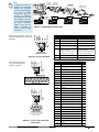
4 Magnet System
Following is a list of the 32-bit signed integer data registers
accessed through the serial port and used as the data source
for all magnet position displays.
Register
Number
Number of Magnets Name Description
Magnet System Description
1 Magnet System Channel 1 data. 32-bit register holds the
processed data for channel 1. 253
CH1
Channel 3 data. 32-bit register holds the
processed data for channel 3. 251CH3
Magnet 1 position
Magnet 1 velocity
Channel 1 data. 32-bit register holds the
processed data for channel 1. 253CH1
Channel 2 data. 32-bit register holds the
processed data for channel 2. 252CH2
Channel 3 data. 32-bit register holds the
processed data for channel 3. 251CH3
Channel 4 data. 32-bit register holds the
processed data for channel 4. 250CH4
Result data. 32-bit register holds the processed
data for result channel. 254RESULT
Magnet 1 position
Magnet 2 position
Magnet 1 velocity
Magnet 2 velocity
Magnet 2 position minus mag-
net 1 position
2 Magnet System
Channel 1 data. 32-bit register holds the
processed data for channel 1. 253CH1
Channel 2 data. 32-bit register holds the
processed data for channel 2. 252CH2
Channel 3 data. 32-bit register holds the
processed data for channel 3. 251CH3
Magnet 1 position
Magnet 2 position
Magnet 3 position
3 Magnet System
Also listed are the registers holding the activation values for set-
points 1 to 6:

Page 20 • BDD-652 Operator's Guide
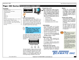
Installation
96 mm
(3.78")
48 mm
(1.89")
3.9 mm
(0.15") typical
FRONT VIEW
1/8 DIN 96x48 mm
These dimensions are
increased by 1.6 mm (0.06")
when the metal surround
case is installed.
The 96x48 mm case is
particularly suitable for
mounting in mosaic panels
or insulative panels up to 2"
thick. They can also stack
mount, 2 up in existing cutouts
for 1/4 DIN (96x96 mm) or 4
up in 1/2 DIN (96X192 mm).
NOTE: The metal surround case
is pre-installed at the factory and cannot
be removed without damage to the case.
Metal Surround Case
P/N:(OP-MTL96X48)
uses
metal screw mount clips
and has a max. panel
thickness mounting
of 15.5 mm (0.61").
Removable
Key-lock
Cam
Opening
Safety
Catch
Clear Lockable NEMA 4X
Splash Proof Cover
P/N:(OP-N4/96x48)
40.8 mm
(1.61")
117 mm
(4.61")
SIDE VIEW
5.3 mm
(0.21")
3.7 mm
(0.15")
43.4 mm
(1.71")
DIN Cutout spacers
Straight-thru Connecto
r
for meters with output
board 20 mm (0.79")
Right-angled Connector
11.8 mm (0.47")
PANEL CUTOUT
Case will mount in standard 1/8 DIN coutouts
45 mm
(1.77")
Snug Fitting
Mosaic Fitting
92 mm
(3.62")
Loose Fitting
91.6 mm
(3.6")
40.8 mm
(1.61")
8 places
3 mm
(0.12")
8 places
4 mm
(0.16") 43.4 mm
(1.71")
1/8 DIN
Cutout spacers
87.4 mm
(3.45")
For additional strength, extra mounting
slide clips can be ordered and doubled up
one behind the other. P/N: (75-DMTCLIPF)
TOP VIEW
87.4 mm
(3.45")
mosaic
fitting
95.4 mm
(3.77")
Max. panel thickness
50 mm
(1.97")
96 mm
(3.78")
91.6 mm
(3.6")
DIN
Cutout
Spacer
To open rear cover,
use a small flat
blade screwdriver.
Press down lightly to
release catch on top
or bottom of case
and lever outwards.
4.7 mm
(0.19")
DIN Cutout Spacer
2 mm
(0.08")
Connector
Socket
When extra panel
mounting tightness is
required, order the
optional screw mount clip.
P/N:(OP-MTLCLIP)
High Strength Panel
Mounting Kit
P/N: OP-PMA96X48
For extra strength in portable applications, the 8 DIN
spacers should be snipped off and the mosaic fitting
cutout used. Alternatively, the High Strength Panel
Mounting Kit (Part # OP-PMA96X48) can be used.
Panel adaptor plates are
available to retrofit most
existing panel cutouts.
Various bezel
colors are available.
Black is standard.
SP1 SP2 SP3 SP4 SP5 SP6
F2
P
F1
SP1 SP2 SP3 SP4 SP5 SP6
F2
P
F1
SP1 SP2 SP3 SP4 SP5 SP6
F2
P
F1
STEP A Prepare the Panel
1) Cut a hole in the panel to suit the panel
cutout. See panel cutout sizes above.
STEP B Install the Meter
1) Remove both mounting clips from the meter.
2) Push the meter into the panel cutout from the
front of the panel.
3) Attach both mounting clips to the meter from
the rear of the panel and push them towards
the front of the panel until the meter is firmly
held.
STEP C Connect the Cables
1) Connect all input and output signal cables to the
connector pins (See Connector Pinouts for details).
2) Connect the power cables to the connector pins
(See Connector Pinouts for details).
WARNING
AC and DC power supply voltages
are hazardous. Make sure the
power supply is isolated before
connecting to the meter.
123
Installation Procedure
6
32-bit register holds the setpoint activation value for setpoint 1.
SETPOINT1
7
32-bit register holds the setpoint activation value for setpoint 2.
SETPOINT2
8
32-bit register holds the setpoint activation value for setpoint 3.
SETPOINT3
9
32-bit register holds the setpoint activation value for setpoint 4.
SETPOINT4
10
32-bit register holds the setpoint activation value for setpoint 5.
SETPOINT5
11
32-bit register holds the setpoint activation value for setpoint 6.SETPOINT6
Register Number
Setpoint Name Description
1
2
3
Page is loading ...
Page is loading ...
Page is loading ...
Page is loading ...
-
 1
1
-
 2
2
-
 3
3
-
 4
4
-
 5
5
-
 6
6
-
 7
7
-
 8
8
-
 9
9
-
 10
10
-
 11
11
-
 12
12
-
 13
13
-
 14
14
-
 15
15
-
 16
16
-
 17
17
-
 18
18
-
 19
19
-
 20
20
-
 21
21
-
 22
22
-
 23
23
-
 24
24


Ask a question and I''ll find the answer in the document
Finding information in a document is now easier with AI
Related papers
-
 Texmate LVDT-200 Owner's manual
-
 Texmate SG100 Weighing Controller Owner's manual
-
 Texmate NZ208 User manual
-
 Texmate GI-50EB101 Owner's manual
-
 Texmate DI-60T Owner's manual
-
 Texmate NZ202 User manual
-
 Texmate NZ201 User manual
-
 Texmate IST8 User manual
-
 Texmate IGYY User manual
-
 Texmate 3.09b Owner's manual


Other documents
-
 Anderson Manufacturing AV-9000 User manual
-
Nakamichi NDSR660A User manual
-
Texas Instruments TMS320C6457 DSP Turbo-Decoder Coprocessor 2 Reference User manual
-
NXP KIT34978EKEVB User guide
-
Novus N2000S User guide
-
Poly VVX 450 OBi Edition Administrator Guide
-
-
Ruck ACCU K 600 F OOJR Owner's manual
-
Schneider Electric altivar 58 telemecanique User manual
-
 AND AD-4430C User manual

