
Serial Comms. Mod. (NZ202) 1
www.texmate.com
Texmate Inc. Tel. (760) 598-9899
Associated Documents
Tiger 320 Series SERIAL COMMUNICATIONS MODULE SUPPLEMENT
Technical Specifications............................................3
Technical Description ..............................................3
Serial Communications Hardware Pinouts & Interconnections . . . . . . . . . 15
Meter Functions using Serial Communications . . . . . . . . . . . . . . . . . . . . . . . 17
Meter Programming Codes.........................................28
Serial Output Configuration Programming Codes . . . . . . . . . . . . . . . . . . . . . 29
Component Layout................................................32
Set Up & Programming Procedures . . . . . . . . . . . . . . . . . . . . . . . . . . . . . . . . . 33
Contents
The following documents must be read
together with this supplement:
Relevant Tiger 320 Series User’s Manual
The user’s manual provides general infor-
mation on the relevant Tiger 320 Series
meter.
Tiger 320 Series Programming Code
Sheet (NZ101)
The programming code sheet provides all
meter programming codes including set-
point programming codes.
Tiger 320 Registers Supplement (CA101)
This supplement provides a detailed descrip-
tion of ASCII and Modbus registers. All avail-
able ASCII and Modbus registers are listed
in tables.
Quick Start Guide for the Tiger
Configuration Utility (Z114)
This supplement provides instructions
on using the Texmate developed Meter
Configuration Utility program.
Macro Programming Tutorial (NZ212)
The tutorial describes the method of writing
a macro for simple to complex applications,
in varying levels of complexity.
List of Figures
Figure 1 – Serial Communications Output Overview . . . . . . . . . . . . . . . . . . . . . . . . . . . . . 3
Figure 2 – Character Frame Formats.......................................... 5
Figure 3 – Timing Diagram . . . ............................................... 7
Figure 4 – Example of a Command String . . . ................................... 9
Figure 5 – Examples of Multiple Write Command. . . . . . . . . . . . . . . . . . . . . . . . . . . . . . . . 9
Figure 6 – RS-232 Hardware Connections . . . . . . . . . . . . . . . . . . . . . . . . . . . . . . . . . . . . . 15
Figure 7 – RS-485 Hardware Connections . . . . . . . . . . . . . . . . . . . . . . . . . . . . . . . . . . . . . 15
Figure 8 – RJ-11 Connections . . . ............................................ 16
Figure 9 – RJ-11 to 9-pin and 25-pin D Connectors . . . .......................... 16
Figure 10 – Programming via Serial Port . . . .................................. 17
Figure 11 – Logging and Printing . . . ......................................... 18
Figure 12 – Retrieving Logged Data.......................................... 21
Figure 13 – Meter Modes for Communication using Print Mode. . . . . . . . . . . . . . . . . . . 22
Figure 14 – Printing Data . . . ............................................... 23
Figure 15 – Combining Two Isolated Inputs. . . . . . . . . . . . . . . . . . . . . . . . . . . . . . . . . . . . 25
Figure 16 – Controlling a Process with Two Meters . . . .......................... 25
Figure 17 – Providing a Second Display. . . . . . . . . . . . . . . . . . . . . . . . . . . . . . . . . . . . . . . 26
Figure 18 – Computer to Meter Control Mode Example. . . . . . . . . . . . . . . . . . . . . . . . . . 26
Figure 19 – Programming Code List.......................................... 28
Figure 20 – Exploded View of Meter Modular Boards . . . ........................ 32
Figure 21 – Meter to Meter Connection through Serial Ports . . . .................. 37
Figure 22 – Computer to Meter Control Mode Example. . . . . . . . . . . . . . . . . . . . . . . . . . 38
Figure 23 – Example Graph in Microsoft Excel. . . . . . . . . . . . . . . . . . . . . . . . . . . . . . . . . 47
This document is designed to supplement the information on the Serial
Communications Output Module described in the Tiger 320 Series
User’s Manual.
Programming Tip
This document has been written
using a DI-50 7-segment, 5-digit
display meter. When program-
ming meters with other display
options, some display read-
ings may vary to the diagrams
shown.
Programming Tip
It is assumed that you are
familiar with the Programming
Conventions used throughout
the range of Texmate Tiger 320
Series literature as described in
the user’s manual.

Texmate Inc. Tel. (760) 598-9899
2 Serial Comms. Mod. (NZ202)
www.texmate.com
PROGRAMMING TIP Symbol
The programming tip symbol is generic to all Tiger 320 Series documents
and indicates useful tips when programming the instrument.
WARNING Symbol
The WARNING symbol is generic to all Tiger 320 Series documents and
indicates that if the instruction is not heeded, the action may result in loss
of life or serious injury.
General Notices & Tips
NOTE Symbol
The NOTE symbol is generic to all Tiger 320 Series User’s Manual
supplements and indicates important or helpful information on the topic
being discussed.
Definitions The following definitions are relevant to the Tiger 320 Series serial output module:
X
If an X appears in the description of a 3-digit programming code or in a configuration proce-
dure, this means that any number displayed in that digit is not relevant to the function being
explained, or more than one choice can be made.
Meter – Controller
The term meter, as used throughout this document, is a generic term for all Tiger 320 Series
signal processors and controllers.
The range of Tiger 320 Series supplements contain three graphic symbols to aid you:
TDS – Tiger Development System
To further enhance the control and automation functionality of the Tiger 320’s operating sys-
tem, a compiler program, known as the Tiger Development System (TDS), allows Texmate
or our customer to customize the controller with a standard or unique macro for almost any
OEM application.

Serial Comms. Mod. (NZ202) 3
www.texmate.com
Texmate Inc. Tel. (760) 598-9899
The standard serial communications output module is one of three serial output options
available with Tiger 320 Series meters.
An RS-232 or RS-485 serial interface board is mounted directly on the meter’s output carrier
board during factory installation. Both RS-232 and RS-485 communicate with an external
device using the ASCII or ModBus mode.
Only one serial interface board, either RS-232 or RS-485, can be mounted in the meter at
any time.
Standard Serial Output Module: Isolated RS-232 or isolated RS-485 serial interface using a
simple, Texmate developed, isolated ASCII communication
protocol (uses standard ASCII character set) or ModBus
communication protocol.
Data: 8-bit.
Parity: None, Odd, Even.
Baud Rate: 600,1200, 2400,4800, 9600,19200, 38400 Kb/s.
Bus Address: 1 to 255.
Multi-device Connection: Up to 64 devices connected in
parallel or series using RS-485 serial interface.
Ethernet Module:
Isolated Ethernet Output Module using either the Modbus/TCP
communication protocol or connecting ASCII communication
TCP/IP.
Technical Description
Technical
Specifications
Interface Standards
There are three serial interface standards commonly found in use today: RS-232, RS-
422, and RS-485. The three interfaces are Electrical Industry Association (EIA) stan-
dards that define the 25-pin interconnection of Data Terminal Equipment (DTE) and Data
Communication Equipment (DCE). The interface standards use serial binary interchange
between two devices to communicate with each other.
A DTE transmits data on the transmitted data (TXD) line and receives data on the received
data (RXD) line. Conversely, a DCE receives data on the TXD line and transmits data on
the RXD line.
Depending on the application, Tiger 320 Series meters are normally connected using either
RS-232 or RS-485.
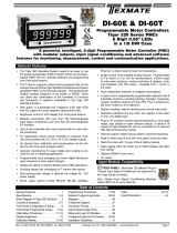
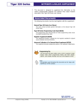
FUNCTIONS AVAILABLE
WITH SERIAL COMMS
HARDWARE
INTERFACE
Serial
Communications
Port • RS-232
• RS-485
COMMUNICATION
PROTOCOL
• ASCII
• MODBUS
• Meter Programming via PC
• Data Logging
• Print Mode
– Download to PC
– Download to Serial Printer
• Meter to Meter Comms
• Computer to Meter Control Mode
• Master Mode
– Configure using Texmate
Meter Configuration Program
– Read from / Write to Meter
Registers using Terminal
Emulation Program
EQUIPMENT
TYPE
• DCE – Computer
• DTE – Meter, Printer
Note:
Connecting a meter to
a printer may require a
null modem adaptor
Figure 1 – Serial Communications Output Overview

Texmate Inc. Tel. (760) 598-9899
4 Serial Comms. Mod. (NZ202)
www.texmate.com
RS-232 Serial Communication Interface
The RS-232 interface supports transmission lengths of up to 15 meters (50 feet), although
this distance is pushed further in practice.
RS-422 Serial Communication Interface
The distance limitation of RS-232 is overcome with the RS-422 interface. RS-422 supports
transmission lengths of up to 1000 meters (3600 feet). Both RS-232 and RS-422 support
connection between only two devices on the bus at one time. RS-422 uses a 4-wire design
consisting of:
• Transmit+.
• Transmit–.
• Receive+.
• Receive –.
See Serial Communications Hardware Pinouts & Interconnections on Page 15 for
information on RS-232 and RS-485 connection details.
See Serial Communications Interface Setup Procedure on Page 39.
Communication Formats
ASCII Mode
The ASCII mode is a simple, Texmate developed, isolated ASCII communication
protocol using the standard ASCII character set. This mode provides external communication
between the meter and a PC allowing remote programming to be carried out.
Tiger 320 Series meters use a serial communication channel to transfer data from the meter
to another device. With serial communications, data is sent one bit at a time over a single
communications line. The voltage is switched between a high and a low level at a predeter-
mined transmission speed (baud rate) using ASCII encoding. Each ASCII character is trans-
mitted individually as a byte of information (eight bits) with a variable idle period between
characters. The idle period is the time between the receiving device receiving the stop bit of
the last byte sent and the start bit of the next byte. The receiving device (for example a PC)
reads the voltage levels at the same interval and then translates the switched levels back to
an ASCII character. The voltage levels depend on the interface standard being used.
Table 1 lists the voltage level conventions used for RS-232 and RS-485. The voltage levels
listed are at the receiver.
See Table 2 for a list of the most commonly accessed ASCII mode registers.
1elbaT snoitnevnoCleveLegatloVecafretnI
cigoL etatSecafretnI 232-SR 584-SR
1 )eldi(kraM V51-ot3-:DXR,DXT Vm002-<b+a
0 )evitca(ecapS V51+ot3+:DXR,DXT Vm002+>b-a
Note:
Tiger 320 Series meters do not use the RS-422 interface.
RS-485 Serial Communication Interface
The RS-485 interface supports similar transmission distances to RS-422, as well as multi-
drop operation where up to 64 devices may be connected at one time. RS-485 uses a 2-wire
system with a plus and minus signal line to transmit and receive data. Therefore, RS-485
is always half-duplex because it cannot transmit and receive data simultaneously. When a
device needs to send data, it connects its transmitter to the signal lines, and when it needs
to receive data, it connects its receiver to the signal lines.
If more than one receiving device is connected to the interface, a unique node address must
be assigned to each device. The node address must preface each command. If only one
device is connected, the node address specifying command may be ignored.
The node address is set in the Calibration Mode.

Serial Comms. Mod. (NZ202) 5
www.texmate.com
Texmate Inc. Tel. (760) 598-9899
Each ASCII character is 'framed' with:
• A start bit.
• An optional error detection parity bit.
• And one or more ending stop bits.
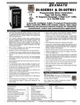
For communication to take place, the data format and baud rate (transmission speed) must
match that of the other equipment in the communication circuit. Figure 2 shows the character
frame formats used by the meter.
Idle 0 b0b1b2b3b4b5b6Idle
8 data, no parity, 1 stop
Idle 0 b0b1b2b3b4b5b6PIdle
1
8 data, parity, 1 stop
Note: b0 to b7 is ASCII data.
Start
Bit
Stop
Bit
1
Receiving Device (PC)
Sending Device (Meter)
Data Bits
b7
b7
Stop
Bit
Parity
Bit
Figure 2 – Character Frame Formats
Modbus Mode
The Modbus mode uses the Modbus communication protocol to provide external communica-
tion between a controller (Tiger 320 Series meter) and a process device for monitoring, control,
and automation purposes.
Tiger 320 Series meters use Modbus RTU (Remote Terminal Unit) communication. This is
an 8-bit binary transmission mode. In the Modbus mode the controller acts as a slave to a
Modbus master (PC or PLC). Data transfers are based on registers and can only be initiated
by the Modbus master. Table 2 lists the most commonly accessed Modbus mode registers,
which contain 32-bit fixed point data.
The Modbus master must be configured to accept this type of data. Once this is done, seam-
less communication between the Modbus master and Modbus slave can be initiated.
The main advantage of this mode is that its greater character density allows better data
throughput than ASCII for the same baud rate. Each message must be transmitted in a
continuous stream.
See Table 2 for a list of the most commonly accessed Modbus mode registers.
Note:
It is beyond the scope of this supplement to describe the Modbus communication
format protocol.
For detailed information on ASCII and Modbus mode registers, see Tiger 320
Registers Supplement (CA101).

Texmate Inc. Tel. (760) 598-9899
6 Serial Comms. Mod. (NZ202)
www.texmate.com
Character Frame Formats
Start Bit and Data Bits
Data transmission always begins with the start bit. The start bit signals the receiving device
to prepare to receive data. One bit period later, the least significant bit of the ASCII encoded
character is transmitted, followed by the remaining data bits. The receiving device then reads
each bit position as they are transmitted and, since the sending and receiving devices operate
at the same transmission speed (baud rate), the data is read without timing errors.
Parity Bit
To prevent errors in communication, the sum of data bits in each character (byte) must be the
same: either an odd amount or an even amount. The parity bit is used to maintain this similarity
for all characters throughout the transmission.
It is necessary for the parity protocol of the sending and receiving devices to be set before
transmission. There are three options for the parity bit, it can be set to either:
• None – which means there is no parity.
• Odd – which means the sum of bits in each byte is odd.
• Even – which means the sum of bits in each byte is even.
After the start and data bits of the byte have been sent, the parity bit is sent. The transmit-
ter sets the parity bit to 1 or 0 making the sum of the bits of the first character odd or even,
depending on the parity protocol set for the sending and receiving devices.
As each subsequent character in the transmission is sent, the transmitter sets the parity bit to a 1
or a 0 so that the protocol of each character is the same as the first character: odd or even.
The parity bit is used by the receiver to detect errors that may occur to an odd number of bits
in the transmission. However, a single parity bit cannot detect errors that may occur to an even
number of bits. Given this limitation, the parity bit is often ignored by the receiving device. The
user sets the parity bit of incoming data and sets the parity bit to odd, even or none (mark
parity) for outgoing data.
The parity bit is set in the Calibration Mode.
2elbaT )sretsigeRtib-23(sretsigeRsubdoMdnaIICSAnommoC
#N.geRIICSA noitcnuF #N.geRsubdoM
1sutatSmralA 00004
2retsigeRyalpsiD 31504
3tluseRataDdessecorP 51504
41lennahC–ataDdessecorP 71504
52lennahC–ataDdessecorP 91504
93 3lennahC–ataDdessecorP 12504
04 4lennahC–ataDdessecorP 32504
61tniopteS 53504
72tniopteS 73504
83tniopteS 93504
94tniopteS 14504
01 5tniopteS 34504
11 6tniopteS 54504
21 kaeP 52504
31 yellaV 72504
41 eraT 33504
51 esUetamxeTrofdevreseR –
61 1latoT 92504
71 2latoT 13504
1

Serial Comms. Mod. (NZ202) 7
www.texmate.com
Texmate Inc. Tel. (760) 598-9899
Stop Bit
The stop bit is the last character to be transmitted. The stop bit provides a single bit period
pause to allow the receiver to prepare to re-synchronize to the start of a new transmission (start
bit of next byte). The receiver then continuously looks for the occurrence of the start bit.
Note:
Tiger 320 Series meters use only one stop bit.
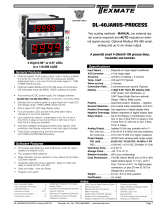
Command Response Time
The meter uses half-duplex operation to send and receive data. This means that it can only
send or receive data at any given time. It cannot do both simultaneously. The meter ignores
commands while transmitting data, using RXD as a busy signal.
When the meter receives commands and data, after the first command string has been
received, timing restrictions are imposed on subsequent commands. This allows enough
time for the meter to process the command and prepare for the next command.
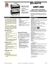
See Figure 3. At the start of the time interval t1, the sending device (PC) prints or writes
the string to the com port, thus initiating a transmission. During t1 the command characters
are under transmission and at the end of this period the command terminating character is
received by the meter. The time duration of time interval t1 is dependent on the number of
characters and baud rate of the channel:
t1 = (10 * # of characters) / baud rate
At the start of time interval t2, the meter starts to interpret the command, and when complete
performs the command function.
After receiving a valid command string, the meter always indicates to the sending device
when it is ready to accept a new command. After a read command, the meter responds with
the requested data followed by a carriage return (øDH) and a line feed (øAH) character. After
receiving a write command, the meter executes the write command and then responds with
a carriage return/line feed.
The sending device should wait for the carriage return/line feed characters before sending
the next command to the meter.
If the meter is to reply with data, time interval t2 is controlled by using the command termi-
nating character: $ or *. The $ terminating character results in a response time window of 50
ms minimum and 100 ms maximum. This allows enough time to release the sending driver
on the RS-485 bus. Terminating the command line with the * symbol, results in a response
time window (t2) of 2 ms minimum and 50 ms maximum. The faster response time of this
terminating character requires that sending drivers release within 2 ms after the terminating
character is received.
At the start of time interval t3, the meter responds with the first character of the reply. As with t1,
the time duration of t3 is dependent on the number of characters and baud rate of the channel:
t3 = (10 * # of characters) / baud rate
At the end of t3 the meter is ready to receive the next command.
The maximum throughput of the meter is limited to the sum of the times: t1, t2, t3.
Note:
The command response time delay for the Modbus format is set in the Calibration
Mode. See Serial Communications Settings Configuration Procedures on Page 33.
Ready t1
Response From The Meter
Command
Terminator
Received
t2
First
Character
of Reply
Ready
t3
Reply
Transmission
Time
Figure 3 – Timing Diagram

Texmate Inc. Tel. (760) 598-9899
8 Serial Comms. Mod. (NZ202)
www.texmate.com
ASCII Serial Mode Read/ Write Information
ASCII Command Character Descriptions
Table 3 describes the functions of the command string characters. Table 4 shows examples
of how the command string is constructed.
4elbaT selpmaxEgnirtSdnammoCIICSA
gnirtSdnammoC noitpircseDgnirtSdnammoC
$RS .dnopsersretemlla,yaledsm05,eulavyalpsiddaeR
$r51s .sdnopser51sserddaretem,yaledsm05,eulavyalpsiddaeR
*21RS .dnopsersretemlla,yaledsm2,eulavkaepdaeR
*031rS .dnopsersretemlla,yaledsm2,gnittes1edoCdaeR
$00001-2w2s .yaledsm05,2sserddaretemforetsigeryalpsidehtot00001etirW
$1_nahCTWS gnirtstxetIICSAetirW 1_nahC .sm05,Tretsigertxetot
*7,841w01S .yaledsm2,01sserddaretemno7otssenthgirbegnahC
3elbaT snoitpircseDretcarahCdnammoC
dnammoC noitpircseD noitcnuF
Sro stratS
retcarahC
ehT retcarahctrats .gnirtsehtniretcarahctsrifehtebtsum
0ot 552 )edoN(reteM
sserddA
reificepS
siretcarahctratsehtgniwollofretcarahcehtfI.retemcificepsaotsserddanasngissaretcarahctxenehT
.demussasi0sserddaneht,rebmunIICSAnaton
.0sserddaotdnopsersretemllA
Rro rrof
daer
Wro wrof
etirw
etirW/daeR
dnammoC
ehtsiretcarahctxenehT dnammocetirw/daer .retcarahc
ehT dnammocdaer .retemehtmorfretsigerasdaer
ehT dnammocetirw .retemehtforetsigeraotsetirw
noitarepoehttroballiwretcarahcetirwrodaerehtrofretcarahcrehtoynagnisU
IICSA
rebmun 1ot
53556
retsigeR
sserddA
ehT sserddaretsiger morfrebmunIICSAnaebrehtienactI.txendeificepssinoitarepoetirw/daerehtrof
.)evitisnesesacton(RotAmorfrettelIICSAnagniretneybdesseccaebnac81ot1retsigerro53556ot1
eulavatadehthtiwdnopsersyawlalliwretemeht,dnammocdaeranidettimosiretcarahcsserddaehtfI
.yalpsidehtnoyltnerruc
.dnammocetirwarofdeificepsebtsumsserddaretsigerehT
ecapS ro
"",
rotarapeS
retcarahC
IICSAnanahtrehtognihtemosebtsumretcarahctxeneht,dnammocetirwanisserddaretsigerehtretfA
aebnactI.eulavatadehtmorfsserddaretsigerehtetarapesotdesusisihT.rebmun ecaps "aro ", ynaro
"atpecxeretcarahcrehto $"aro" *."
egnaR
neewteb
9999999–
ot 9999999
eulaVataD eht,retcarahcrotarapesehtretfA eulavatad foegnarehtnirebmunIICSAnaebtsumtI.tnessi 9999999–
ot 9999999 .)retsigeRtnioPdexiF(
.desseccasiretsigerhcihwnognidnepedyravlliwegnarehT:etoN
$ro *egasseM
rotanimreT
ehtsiegassemehtniretcarahctsalehT rotanimretegassem rehtieebtsumsihT. $ro *.
ehtfI $.tnessiylperaerofebdetresnisism05foyaledmuminima,rotanimretasadesusi
ehtfI *.tnessiylperaerofebdetresnisism2foyaledmuminima,rotanimretasadesusi
ehT $dna *.gnirtsegassemehtniesleerehwynaraeppatontsumsretcarahc
FL/RC reteM
esnopseR
agnidnesybsdnopserti,noitcurtsnietirwrodaeradetelpmocsahretemehtretfA deefenil/nruteregeirrac
IICSAehtniretcarahctsalehtswollofFL/RCeht,dnammocdaerasawnoitcurtsniehtfI.tsohehtotkcab
roftiawtsumtsohehT.tsohehtotkcabtnesesnopserylnoehtsiFL/RCeht,dnammocetirwasawtifI.gnirts
.retemehtotsdnammocrehtrufynagnidneserofebsiht
.FL/RCaybdewollofretcarahcllunasecudorp,retsigertnatsixe-nonrodilavtonaotetirwrodaerA

Serial Comms. Mod. (NZ202) 9
www.texmate.com
Texmate Inc. Tel. (760) 598-9899
Multiple Write
The multiple write feature of the Tiger meter allows multiple registers to be written to in a
single ASCII command string. It is similar to a normal write command but with the following
differences:
• After the first data value, a separator character is inserted instead of the message terminator.
The next register address is then specified, followed by another separator character and the
next data value. This procedure is repeated for each new register. The message terminator
is added after the last data value in the string.
• Any number of registers can be written to using the multiple write feature, as long as the total
length of the command string does not exceed 73 ASCII characters, including spaces and
the message terminator.
Figure 5 shows two examples of the multiple write command.
Note:
The multiple write feature cannot be used with special ASCII registers (H to X).
Start
Character
Meter
Address
Read/Write
Command
Register
Address
Separator
Character
Data
Value
Message
Terminator
SW6,10000,7,20000,8,30000$
Start
Character
Meter
Address
Read/Write
Command
Register
Address
Separator
Character
Data
Value
Message
Terminator
Start
Character
Meter
Address
Read/Write
Command
Register
Address
Separator
Character
Data
Value
Message
Terminator
S2w6 -32766 7 32766*
Figure 5 – Examples of Multiple Write Command
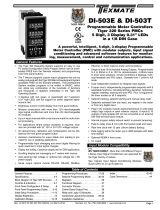
Command String Construction
When sending commands to the meter using a Terminal emulation program, a string con-
taining at least one command character must be constructed. A command string consists
of the following characters and must be constructed in the order shown:
1) A start character.
2) The meter (node) address (optional).
3) The read/write command.
4) The register address.
5) A separator character.
6) The data value.
7) The message terminator.
Figure 4 shows an example of a command string.
Start
Character
Meter
Address
Read/Write
Command
Register
Address
Separator
Character
Data
Value
Message
Terminator
Sr130*
Figure 4 – Example of a Command String

Texmate Inc. Tel. (760) 598-9899
10 Serial Comms. Mod. (NZ202)
www.texmate.com
Special ASCII Registers
Tiger 320 Series meters can have either 5-digit or 6-digit displays using either 7-segment or
15-segment display LEDs. Table 5 shows which characters can be used with a 7-segment
display LED along with the associated ASCII value. Table 6 shows which characters can be
used with a 15-segment display LED along with the associated ASCII value.
7-Segment ASCII Characters
Some characters, such as Kk, Mm, Qq, Ww, Zz, can not be displayed correctly on a 7-seg-
ment LED display (Note this does not apply to characters on 15-segment displays). For
these characters the closest possible display has been chosen. The letters M and W can
only be represented by using two digits of the display. This means that each time an M or W
is used, the maximum amount of characters to be displayed is reduced by one (e.g. Power
would be displayed as Powr). If both letters are used, for example in the abbreviation MW for
megawatt, the amount of characters to be displayed is reduced by two. Upper or lower case
letters are accepted by the meter but the resulting display is set to the standard 7-segment
character map. See Table 5.
5elbaT yalpsiDtnemgeS-7rofsretcarahCIICSA
retcarahC )lamiceD(eulavlortnoCretsigeR retcarahC )lamiceD(eulavlortnoCretsigeR
ecapS 23 @46
!33 A56
"43 b66
#)detroppuston(53 C76
$)detroppuston(63 d86
%)detroppuston(73 E96
&)detroppuston(83 F07
'93 G17
(04 H27
)14 i37
*)detroppuston(24 J47
+)detroppuston(34 k57
,)tnioplamicedsadeyalpsid(44 L67
-54 M)stigidowtseriuqertub,detroppus(77
.64 n87
/74 o97
084 P08
194 q)detroppuston(18
205 r28
315 S38
425 t48
535 u58
645 V68
755 W)stigidowtseriuqertub,detroppus(78
865 X88
975 Y98
:)tnioplamicedsadeyalpsid(85 Z)"2"saemas(09
;)tnioplamicedsadeyalpsid(95 [)"C"saemas(19
<06 \29
=16 ]39
>26 ^49
?36 _59

Serial Comms. Mod. (NZ202) 11
www.texmate.com
Texmate Inc. Tel. (760) 598-9899
6elbaT yalpsiDtnemgeS-51rofsretcarahCIICSA
retcarahC )lamiceD(eulavlortnoCretsigeR retcarahC )lamiceD(eulavlortnoCretsigeR
ecapS 23 @46
!33 A56
"43 b66
#53 C76
$63 d86
%73 E96
&83 F07
'93 G17
(04 H27
)14 i37
*24 J47
+34 k57
,44 L67
-54 M77
.64 n87
/74 o97
084 P08
194 q18
205 r28
315 S38
425 t48
535 u58
645 V68
755 W78
865 X88
975 Y98
:)tnioplamicedsadeyalpsid(85 Z09
;95 [)"C"saemas(19
<06 \29
=16 ]39
>26 ^49
?36 _59
Registers H to W – Display Customizing
Text can be customized on the following text displays to suit a particular application:
• Register H – Text display for peak.
• Register I – Text display for valley.
• Register J – Text display for total.
• Register K – Text display for sub-total.
• Register L – Text display for setpoint 1.
• Register M – Text display for setpoint 2.
• Register N – Text display for setpoint 3.
• Register O – Text display for setpoint 4.
• Register P – Text display for setpoint 5.

Texmate Inc. Tel. (760) 598-9899
12 Serial Comms. Mod. (NZ202)
www.texmate.com
• Register Q – Text display for setpoint 6.
• Register R – Text display for overrange.
• Register S – Text display for underrange.
• Register T – Text display for channel 1.
• Register U – Text display for channel 2.
• Register V – Text display for channel 3.
• Register W – Text display for channel 4.
For 5-digit meters the text string displayed by the meter can be 5 ASCII characters long. For
6-digit meters the text string displayed by the meter can be 6 ASCII characters long.
If a text string is read in the usual manner. For example, SRT$, where:
• S for the start character.
• R for the read character.
• T for the text display for Channel 1.
• $ for the message terminator.
The meter responds by displaying the stored string: CH_1.
To customize the text string of the text display for Channel 1, from CH_1 to Hello, issue the
following command:
SWT Hello$
When the text display for Channel 1 is displayed on the meter, instead of CH_1 being dis-
played, Hello is now displayed.
Register X – Print String
The print mode allows the meter to print data from any meter register directly to a serial
printer, or to a PC where it can be imported into a spreadsheet.
Register X is a special register that allows you to specify the text and data stored in specific
registers to be printed out when a print command is issued by the meter while in the print
mode. Through the serial port, register X can be either written to or read from using a ter-
minal program on a PC.
Writing To Register X
Writing to register X tells the meter to print the data stored in one or more of the meter's
registers when the print command is issued. To get the meter to print, the printer must be
connected to the meter through the serial port and the meter must be programmed to [XX3]
in Code 3. The data to be printed depends on how the meter has been programmed, for
example, to display a flow rate and total.
The total length of a write string can be up to 30 ASCII characters long
See Printing Restrictions on Page 13.
Reading From Register X
Reading from register X allows you to check your settings prior to removing the PC from
the serial port and connecting to a printer. Register X can be read in the normal manner
(i.e. SRX$).
Example of Writing To Register X
The following example shows a write to register X with the meter set to display flow rate and
total flow of channel 1 in Code 2.
swx Rate = ~2 (add carriage return and line feed)
Total = ~16$
The above write to register X means the following:
swx: Start writing to register X.
Rate =: Tells the meter to print the word Rate =.
~2: Tells the meter to print the current flow rate (display data), held in register 2, after
the word Rate =.
Total =: Tells the meter to print the word Total =.
~16: Tells the meter to print the current total flow (stored data), held in register 16,
after the word Flow =.
The printer would then print, for example, the following:

Serial Comms. Mod. (NZ202) 13
www.texmate.com
Texmate Inc. Tel. (760) 598-9899
Up to seven different registers can be specified in one text string, provided that the total
string length is no greater than 30 bytes long and the total length of the resulting printout is
less than 100 bytes long (including time stamp if selected).
For example, the following tab delimited output could be specified to input display data, pro-
cessed result, processed channel 1, processed channel 2, peak, valley, and total, directly
into a spreadsheet:
swx ~2(tab)~3(tab)~4(tab)~5(tab)~12(tab)~13(tab)~p$
When calculating the length of the printout, an allowance of 7 bytes for each register address
should be used, plus any extra text or separating characters such as tabs or spaces.
Note:
As a new line is usually represented by a carriage return and a line feed, two bytes
should be added for each new line in text string length calculations.
Rate = 2000
Total = 25000
This means that the current flow rate is 2000 and the total flow at this point is 25000.
Example of Reading From Register X
Having written the above example to the meter, to check the contents of register X using the
terminal program through the PC, type the following:
srx$
The following is shown on the PC screen:
Rate = ~2
Total = ~16$
Printing Restrictions
When printing, any alphanumeric ASCII character can be used within the following restrictions:
• The $ and * characters are reserved for the terminating character at the end of the string and
cannot be used as part of the text string.
• The total string length must be no greater than 30 bytes long. This includes spaces, tabs,
carriage returns, line feeds, and the terminating character. There must be a separator space
between the register address X and the start of the string. This separator space does not
have to be included in text string length calculations.
• Any number following a ~ character will be interpreted as a register address. During a print-
out the register's current value will be printed out in this position.
• The ASCII character \ is treated as a special character in the print string. When a \ is encoun-
tered, a * is printed in its place (* is reserved as a terminating character and normally can not
appear anywhere in the text string). This allows the print output of one meter to be connected
to another meter that is operating in the ASCII mode.
See Meter to Meter Communication on Page 24.
For example, if the print string reads:
swx sw3 ~5\ sw4 ~12\ sw6 ~2\$
The printer prints the following:
sw3 (CH2)* sw4 (PEAK)*
sw6 (DISPLAY)*

Texmate Inc. Tel. (760) 598-9899
14 Serial Comms. Mod. (NZ202)
www.texmate.com
Serial Output Module Settings
Setting the 1st digit to 2 and the 2nd digit to 0 [CAL] [20X] accesses the serial communica-
tions output module properties: baud rate, parity, transmit time delay, and address settings.
Baud Rate
The baud rate range is selectable from 600 to 38400 baud. The default baud rate is 9600.
• 600.
• 1200.
• 2400.
• 4800.
• 9600.
• 19200.
• 38400.
Parity
The default parity setting is [oFF]. Parity [odd] or [EVEn] can also be selected.
Transmit Time Delay
The transmit time delay restricts the meter from transmitting a reply to a slow or busy master
device (PC, PLC, etc.) by providing time delays of 2, 20, 50, or 100 milliseconds for all serial
modes except ASCII (Code 3 set to XX0).
The ASCII Mode uses message terminating characters:
• * = 2 milliseconds.
• $ = 50 milliseconds.
Address
For RS-485 serial communications the default address setting is 1, but can be set to any-
where between 1 and 255.

Serial Comms. Mod. (NZ202) 15
www.texmate.com
Texmate Inc. Tel. (760) 598-9899
Serial
Communications
Hardware Pinouts &
Interconnections
Figure 6 shows a simple
RS-232 connection
between a Tiger 320
Series meter and a PC.
This setup could be
used for remote pro-
gramming of the meter
using the Texmate Meter
Configuration Program.
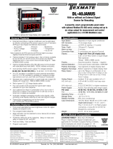
RS-232 Interconnections
Hardware Requirements
The following hardware is required to set the meter up for simple RS-232 communications
(see Figure 6):
• Tiger 320 Series meter with RS-232 serial output module option installed.
• RJ-11 to DB-25 interface connector (and possibly a DB-25 to DB-9 interface connector
depending on PC serial port).
• Standard 4-wire cable with male RJ-11 connectors (see Figure 8 and 9, and Tables 7 and 8
for a wiring diagram and pin descriptions).
• PC running a terminal program.
Figure 7 – RS-485 Hardware Connections
DB-25 Female to RJ-11
Interface Connector
Rear of DI-50T Meter
PC Running
Terminal Program
2-wire Cable
with RJ-11
Connectors
Rear of DI-50T Meter Rear of DI-50T Meter Rear of DI-50T Meter
Texmate Isolated
Converter
(DB-25 Male to
DB-25 Female)
DB-25 Male to
DB-9 Female
Interface Connector
DB-9 Female
Connector to
PC Serial Port
Up to 64 meters
can be connected
30 29 28 27 26 25 24 23 17 16
14 158 910 11
Input Module
(See specific input module data
sheet for connection details)
12 3 4 56
30 29 28 27 26 25 24 23 17 16
14 158 910 11
Input Module
(See specific input module data
sheet for connection details)
123 4 56
RJ-11 Dual
Outlet Adapter
30 29 28 27 26 25 24 23 17 16
14 158 910 11
Input Module
(See specific input module data
sheet for connection details)
123 4 56
RJ-11 Dual
Outlet Adapter
30 29 28 27 26 25 24 23 17 16
14 158 910 11
Input Module
(See specific input module data
sheet for connection details)
12 3 4 56
RJ-11 Dual
Outlet Adapter
DB-25 female to RJ-11
Interface Connector
Rear of DI-50 Meter
PC Running
Terminal Program
4-wire Telephone
Cable with RJ-11
Connectors
30 29 28 27 26 25 24 23 17 16
14 158 910 11
Input Module
(See specific input module data
sheet for connection details)
123 4 56
21 20 19 18
DB-9 Female to RJ-11
Interface Connector
OR
Figure 6 – RS-232 Hardware Connections
RS-485 Interconnections
Hardware Requirements
The following hardware is required to set the meter up for simple RS-485 communications
(see Figure 7):
• A number of Tiger 320 Series meters with an RS-485 serial output module option installed
(this can be up to 64 meters).
• A number of RJ-11 dual outlet adapters to connect the meters in series (amount depends
on the number of meters installed).
• RJ-11 to DB-25 interface connector.
• Texmate isolated converter (RS-485 to RS-232)
• Possibly a DB-25 to DB-9 interface connector depending on PC serial port.
• Lengths of standard 2-wire telephone cable with male RJ-11 connectors (enough to connect
the meters in series and connect to the RJ-11 to DB-25 interface connector). See Figure 9
and Table 8 for a wiring diagram and pin descriptions.
• PC running a terminal program.
Figure 7 shows a number of Tiger 320 Series meters with the hardware required to connect
directly to a PC using RS-485. This setup could be used for remote programming of each
meter using the Texmate Meter Configuration Program from a single PC.

Texmate Inc. Tel. (760) 598-9899
16 Serial Comms. Mod. (NZ202)
www.texmate.com
Note:
In theory, up to 64 meters can be connected together. The meters can be connected
together in series or parallel using RJ-11 type connectors or hardwiring (each meter
can only be hardwired if it has a screw terminal instead of an RJ-11 connecter).
Figure 7 has the meters connected in series using RJ-11 type connectors.
RJ-11
Socket
Isolated
GND
TXD
RXD
Reserved
Optional
+5 VDC
Reserved
See Table 7
65 4 321
Table 7 lists the pinouts for an RS-232 or RS-485 to RJ-11 socket configuration for Terminal 5 on Tiger
320 Series DI and GI meter case configurations and Terminal 6 on FI meter configurations.
Figure 9 – RJ-11 to 9-pin and 25-pin
D Connectors
14
1
15
2
16
3
17
4
18
5
19
6
20
7
21
8
22
9
23
10
24
11
25
12
13
6
1
7
2
8
3
9
4
5
25-Pin D Connector
(See Table 8 for pin descriptions)
(Viewed from the pin side of a female connector)
9-Pin D Connector
(See Table 8 for pin descriptions)
(Viewed from the pin side of a
female connector)
RJ-11
Connector
Socket
Isolated
GND
TXD
RXD
Reserved
Optional
+5 VDC
Reserved
Isolated
GND
TXD
RXD
Reserved
Optional
+5 VDC
Reserved
RJ-11
Connector
Socket
Figure 8 – RJ-11 Connections
Table 8 lists the pinouts for an RS-232 to
9-pin or 25-pin D connector.
8elbaT srotcennoCDniP-9&niP-52ot232-SR
niP-52 emaNniP niP-9
1dnuorGemarF -
2ataDevieceR 3
3ataDtimsnarT 2
4dneSottseuqeR 7
5dneSotraelC 8
6ydaeRteSataD 6
7dnuorGlangiS 5
8tceteDreirraCataD 1
9devreseR -
01 devreseR -
11 dengissanU -
21 tceteDreirraC.ceS -
31 dneSreirraC.ceS -
41 ataDtimsnarT.ceS -
51 kcolCrettimsnarT -
61 ataDevieceR.ceS -
71 kcolCrevieceR -
81 kcabpooLlacoL -
91 dneSottseuqeR.ceS -
02 ydaeRlanimreTataD 4
12 tceteDytilauQlangiS/kcabpooLetomeR
22 rotacidnIgniR 9
32 tceleSetaRataD -
42 kcolCrettimsnarT -
52 edoMtseT -
TERMINAL PINS RS-232 RS-485
1 Reserved for future use Reserved for future use
2 RXD. Received Serial B (Low)
3 TXD. Transmitted Serial A (High)
4
5 Isolated Ground Isolated Ground
6 Reserved for future use Reserved for future use
otCDV5+lanoitpO
lanretxerewop
sretrevnoc
ro232-SRnorepmuj(
ebtsumsdraob584-SR
)deredlos
otCDV5+lanoitpO
lanretxerewop
sretrevnoc
ro232-SRnorepmuj(
ebtsumsdraob584-SR
)deredlos
otCDV5+lanoitpO
lanretxerewop
sretrevnoc
ro232-SRnorepmuj(
ebtsumsdraob584-SR
)deredlos
otCDV5+lanoitpO
lanretxerewop
sretrevnoc
ro232-SRnorepmuj(
ebtsumsdraob584-SR
)deredlos
Table 7 Serial Communication Pinouts (RJ-11 Socket)

Serial Comms. Mod. (NZ202) 17
www.texmate.com
Texmate Inc. Tel. (760) 598-9899
With a serial output module installed, the meter can
be fully configured using a PC and either:
• The Tiger Configuration Utility Program.
• Or a terminal emulation program such as
HyperTerminal.
Meter Functions using
Serial Communications
Meter Programming via Serial Port
Prog.
SP1 SP2 SP4SP3 SP5 SP6
TEXMATE
Figure 10 – Programming via Serial Port
Tiger Configuration Utility Program
The Tiger Configuration Utility program is a Texmate developed, intuitive, user oriented
Windows based interface between the PC and the meter. In addition to all application function
settings, the configuration program also provides access to the following additional features.
Code Blanking
Code blanking is used to blank out any codes not used by an application. This makes them
operator tamper-proof, but leaves selected codes open for operator adjustment.
Display Text Editing
Display text editing allows you to edit the display text of a number of display windows to suit
the specifics of your application. For example, a setpoint could be edited to read [TNK_Lo]
for tank level low, or [brKoF] for brake off.
Configuration Data Copying
This function allows the current meter configuration settings to be copied and saved for later
referral or for restoration.
Macros
Texmate has a growing library of macros to suit a wide range of standard customer applica-
tions. Macros can be installed in the meter, via the macro compiler, known as the Texmate
Development System (TDS), or the configuration utility program and run automatically when
the meter is powered up.
For further information, see the Macro Programming Tutorial (NZ212)
With a standard serial output module installed, the meter can be configured for various data
transfer and data capture functions:
• Programming the meter via a PC using a Texmate developed interface program or a terminal
emulation program. See Meter Programming via Serial Port.
• Data logging of process data. See Data Logging.
• Printing data directly to a serial printer for archiving or downloading data to a PC for further
processing. See Data Printing via Print Mode.
• Meter to meter communication to combine two isolated inputs, to control a process, or to
provide a second display. See Meter to Meter Communication.
• Providing manual control over the meter’s inputs and outputs through the computer to meter
control mode. See Computer to Meter Control Mode.
• Control over macro functionality using the macro master mode. See Macro Master Mode on
Page 27.
Terminal Emulation Program
A terminal emulation program, such as HyperTerminal, provides another interface between
a PC and the meter. The terminal program allows you to read from or write to any register
in the meter using an ASCII character command string.

Texmate Inc. Tel. (760) 598-9899
18 Serial Comms. Mod. (NZ202)
www.texmate.com
Data Logging
Data logging function settings are configured in
Code 8.
About 4000 samples (data records) can be stored
(logged) in non-volatile memory for before and after
analysis of any process condition. Up to 1024 kilobits
(128 kilobytes) of on-board memory is available for
continuous loop recording.
Data logging can be triggered (activated) from a set-
point, the program button, or from an external switch.
With a real-time clock installed, date and time
stamps can be included.
Prog.
SP1 SP2 SP4SP3 SP5 SP6
TEXMATE
Data
Logging
Data Data Data Data Data Data
Data Data Data Data Data Data
Data Data Data Data Data Data
Data Data Data Data Data Data
Data Data Data Data Data Data
Data Data Data Data Data Data
Figure 11 – Logging and Printing
Data Logging Concepts
The data logging function uses the concept of pointers to control where a sample is to be
written to and where one is to be read from. These pointers are referred to as the log write
pointer and the log read pointer.
Register 720 – Log Write Pointer
Register 720 is a 16-bit register that points to the most recent log sample written by the
meter. It counts up from 0 each time a new sample is logged, with the maximum number of
samples being limited by the size of non-volatile memory installed in the meter. Before a new
sample is written, the meter first checks to make sure that it is not overwriting a sample that
has not been read. It does this by comparing the write pointer with the read pointer. If they
are the same, data logging is halted until a read is actioned. If this occurs, new samples are
lost. When the sample number reaches the maximum count it either wraps around to zero
or stops logging, depending on what type of buffer has been selected in Code 8: Cyclic or
Linear.
Register 720 can be read from or written to. Make sure that any values written to this pointer
are within the allowable range for the size of the installed memory.
Register 721 – Log Read Pointer
Register 721 is a 16-bit register that points to the most recent log sample read from the
meter. It counts up from 0 each time log data is read from the meter, with the maximum num-
ber of samples being limited by the size of non-volatile memory installed in the meter. When
it reaches the maximum count it either wraps around to zero or stops logging, depending on
what type of buffer has been selected in Code 8: Cyclic or Linear.
Register 721 can be read from or written to. Make sure that any values written to this pointer
are within the allowable range for the size of the installed memory.
Macro Compiler Program
In addition to our library of factory installed macros, customers can write and run their own
unique set of powerful macros to suit their individual OEM applications.
Texmate’s Tiger Development System (TDS) allows customers to write, compile, and down-
load their own macros. These macros can be easily written in BASIC to utilize any combina-
tion of the hundreds of functions embedded into the Tiger 320 Operating System.
This enables customers to use a standard meter for a number of unique applications by
simply writing and downloading their application specific macro.
Texmate Data Viewer
The Texmate Data Viewer is an easy to use graphing and data log extraction package for
the Texmate Tiger series of Programmable Meter Controllers. It reads the data in the data
log for display, export, or graphing. You can also fully configure the data log, and set logging
timers and triggers as well as set Print data for Serial Printers.

Serial Comms. Mod. (NZ202) 19
www.texmate.com
Texmate Inc. Tel. (760) 598-9899
Buffer Types
The 1st digit of Code 8 activates the data logging feature by selecting a data log buffer type.
The meter has two types of buffer.
Cyclic Buffer
Setting Code 8 to 1XX selects the cyclic buffer. In this mode the log write pointer (register
720) increments each time a sample is taken until the number of samples exceed the maxi-
mum sample number – determined by the amount of non-volatile memory installed.
When the cyclic buffer is full, the logged data is replaced on a first on first off basis. This
means that when the buffer is full, the first logged sample is discarded to make way for a
new sample at the end of the logged data string. It then wraps around to sample number 1
again.
See description Register 720 – Log Read Pointer for information about not overwriting old
samples that have not been read.
Linear Buffer
Setting Code 8 to 2XX selects the linear buffer. In this mode the log write pointer is incre-
mented each time a sample is taken until the sample number reaches the maximum sample
number – determined by the amount of non-volatile memory installed. When the linear buffer
is full the meter stops logging data. The buffer must be reset to 0.
Reset Buffer
If Code 8 is set to 3XX the log write and log read pointers are reset to zero when the
PROGRAM button is pressed. Code 8 then reverts back to the same setting it had before
the reset function was executed. Note that when the reset function is executed, the contents
of the buffer is not destroyed, only the pointers are changed.
Register 723 to 726
Registers 723 to 726 are used to specify which registers are to be logged. Register 723
specifies the first register to be logged, 724 the second, 725 the third, and 726 the fourth.
Registers 723 to 726 can be read from and written to as normal registers. Registers 723 to
726 can only be configured via the serial port and are not accessible from the front panel
buttons.
Non-volatile Memory Options
Up to 1024 kilobits of non-volatile on-board memory (EEPROM) can be installed. The num-
ber of samples logged depends on the size of the installed memory:
• 32 kilobits (1 x 32 kb EEPROM):. . . . . . . . . . . . . . . . . . . . . . . . . . . . . . . . . . . . . 88 samples.
• 64 kilobits (1 x 64 kb EEPROM):. . . . . . . . . . . . . . . . . . . . . . . . . . . . . . . . . . . . 216 samples.
• 128 kilobits (1 x 128 kb EEPROM):. . . . . . . . . . . . . . . . . . . . . . . . . . . . . . . . . . 472 samples.
• 256 kilobits (1 x 256 kb EEPROM):. . . . . . . . . . . . . . . . . . . . . . . . . . . . . . . . . . 984 samples.
• 512 kilobits (1 x 512 kb EEPROM):. . . . . . . . . . . . . . . . . . . . . . . . . . . . . . . . . 2008 samples.
• 1024 kilobits (2 x 512 kb EEPROM):. . . . . . . . . . . . . . . . . . . . . . . . . . . . . . . . 3984 samples.
Texmate also offers a data logging module that allows you to store up to 2GB of data (more than
60,000,000 samples) on a removable SD card.
Data Output Format
The second digit of Code 8 configures the data logging and print mode result data with a
time stamp format.
Time Stamp Options
Four different time stamp options are available:
• Time stamp format 0: ............................................No time stamp.
• Time stamp format 1: . . . . . . . . . . . . . . . . . . . . [Month-Date-Year, Hours:Minutes:Seconds].
• Time stamp format 2: . . . . . . . . . . . . . . . . . . . . [Date-Month-Year, Hours:Minutes:Seconds].
• Time stamp format 3: . . . . . . . . . . . . . . . . . . . . . . . . . . . . . . . . . . . [Hours:Minutes:Seconds].

Texmate Inc. Tel. (760) 598-9899
20 Serial Comms. Mod. (NZ202)
www.texmate.com
Note:
Printer style date and time stamps have a carriage return and line feed. Spreadsheet
style time and date stamps are continuous on a single line. All date and time stamps
are generated from the optional real-time clock.
Printer/Spreadsheet Format
Code 8 also allows the time stamp format the selection of a print or spreadsheet style output.
The print style output is designed for printers with a narrow roll of paper. Parameters are
printed down the page with each parameter on a new line using a carriage return and line
feed. The spreadsheet style output is designed for inputting data directly into a computer.
Each sample is printed on a single line with a tab delimiter placed between parameters.
The number of channels that can be logged depends on the use of time stamps and the
amount of non-volatile memory installed:
• Log up to 4 channels:............................................No time stamp.
• Log up to 3 channels:. . . . . . . . . . . . . . Plus time stamp format 3: Hours:Minutes:Seconds.
• Log up to 2 channels:. . . . . . . Plus time stamp format 1: Month-Date-Year. Hrs:Mins:Secs.
• Log up to 2 channels:. . . . . . .Plus time stamp format 2: Date-Month-Year. Hrs:Mins:Secs.
On Demand Log or Print Data Triggers
The 3rd digit of Code 8 provides a feature for logging or printing on demand using one of
the following rear pins or pushbuttons as a trigger source:
• PROGRAM button.
• F1 button (DI-60A5C or DI-802X6C meters only).
• F2 button (DI-60A5C or DI-802X6C meters only).
• HOLD pin (external switch connected to the HOLD and COMMON pin).
• LOCK pin (external switch connected to the LOCK and COMMON pin).
Retrieving Logged Data
Once data has been logged, it can be retrieved using the ASCII Mode or PRINT Mode via
a serial port command.
The ASCII Mode provides greater control of the logged data to be retrieved by reading the
logged data from register 722 and register 727. The log write pointer (register 720) and the
log read pointer (register 721) can also be modified in the ASCII Mode and the most recent
logged data sample in either pointer can be read using a terminal program. See Figure 12.
Table 9 shows the methods available for retrieving logged data.
9elbaT ataDdeggoLgniveirteR
ataDeveirt
e retnioPgoLyfidoM
)0XX–3edoC(edoMIICSA
227retsigeR
retsigermorfdaeR 227 adaolnwodot
.ataddeggolfoelpmaselgnis
)027retsiger(retnioPdaeRgoL
.81egaPnogniggoLataDeeS
727retsigeR
retsigermorfdaeR 727 ehtdaolnwodot
.ataddeggolforeffubelohw
)127retsiger(retnioPetirWgoL
.81egaPnogniggoLataDeeS
)3XX–3edoC(edoMTNIRP
tnirPgoL–L
roreppunagnidnesotsdnopserretemehT
retcarahcIICSAesacrewol L,retemehtot
,ataddeggolfoelpmastxenehtgnitnirpyb
retniopdaergolatadehtybotdetniop
.)127retsiger(
.42egaPnosdnammoCedoMtnirPeeS
ataDgoLraelC–!
IICSAnagnidnesotsdnopserretemehT
retcarahc !htobgniraelcyb,retemehtot
ehtdna)027retsiger(retniopetirwgoleht
)127retsiger(retniopdaergol
egaPnosdnammoCedoMtnirPee
S.42
Page is loading ...
Page is loading ...
Page is loading ...
Page is loading ...
Page is loading ...
Page is loading ...
Page is loading ...
Page is loading ...
Page is loading ...
Page is loading ...
Page is loading ...
Page is loading ...
Page is loading ...
Page is loading ...
Page is loading ...
Page is loading ...
Page is loading ...
Page is loading ...
Page is loading ...
Page is loading ...
Page is loading ...
Page is loading ...
Page is loading ...
Page is loading ...
Page is loading ...
Page is loading ...
Page is loading ...
Page is loading ...
Page is loading ...
Page is loading ...
Page is loading ...
Page is loading ...
-
 1
1
-
 2
2
-
 3
3
-
 4
4
-
 5
5
-
 6
6
-
 7
7
-
 8
8
-
 9
9
-
 10
10
-
 11
11
-
 12
12
-
 13
13
-
 14
14
-
 15
15
-
 16
16
-
 17
17
-
 18
18
-
 19
19
-
 20
20
-
 21
21
-
 22
22
-
 23
23
-
 24
24
-
 25
25
-
 26
26
-
 27
27
-
 28
28
-
 29
29
-
 30
30
-
 31
31
-
 32
32
-
 33
33
-
 34
34
-
 35
35
-
 36
36
-
 37
37
-
 38
38
-
 39
39
-
 40
40
-
 41
41
-
 42
42
-
 43
43
-
 44
44
-
 45
45
-
 46
46
-
 47
47
-
 48
48
-
 49
49
-
 50
50
-
 51
51
-
 52
52


Ask a question and I''ll find the answer in the document
Finding information in a document is now easier with AI
Related papers
-
 Texmate 3.09b Owner's manual
-
 Texmate DI-60AT5C Owner's manual
-
 Texmate SG100 Weighing Controller Owner's manual
-
 Texmate DI-60T Owner's manual
-
 Texmate DI-50EB51 Owner's manual
-
 Texmate LVDT-200 Owner's manual
-
 Texmate DI-503E Owner's manual
-
 Texmate NZ201 User manual
-
 Texmate DL-40JANUS-PROCESS Owner's manual
-
 Texmate DL-40JANUS Owner's manual


Other documents
-
red lion PAXICR User manual
-
-
-
-
Omega DPF9100/DPF9200/DPF9300 Series Owner's manual
-
 NOSHOK 2100 Series Field Upgradeable Dual Input Process Indicator Owner's manual
-
-
-
-
red lion PAXDP User manual
