Page is loading ...

Texmate, Inc.Tel. (760) 598-9899 • www.texmate.com • Setpoints & Relays (NZ201) Page 1
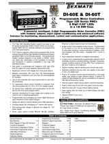
Associated Documents
TTiiggeerr 332200 SSeerriieessSETPOINTS & RELAYS SUPPLEMENT
The following documents must be read together with this supplement:
Relevant Tiger 320 Series User Manual
The users manual provides general information on the relevant Tiger 320
Series meter.
Tiger 320 Series Programming Code Sheet (NZ101)
The programming code sheet provides all meter programming codes includ-
ing setpoint programming codes.
Registers Supplement (NZ209)
This supplement provides a detailed list of all registers available for setpoint
source activation and reset functions.
Advanced Calibration & On Demnad Mode Supplement (NZ203)
This supplement provides detailed descriptions on all calibration related topics.
This document is designed to supplement the information on the
meter’s programmable setpoints and optional relay output modules
described in the Tiger 320 Series user manual.
Programming Tip
This document has been written using a DI-50 7-segment, 5-digit
display meter. When programming meters with other display
options, some display readings may vary to the diagrams shown.
Note:
All examples used throughout this document are for relays with
NORMALLY OPEN contacts.

Texmate Inc.Tel. (760) 598-9899 • www.texmate.comPage 2 • Setpoints & Relays (NZ201)
PROGRAMMING TIP Symbol
The programming tip symbol is generic to all Tiger 320 Series documents
and indicates useful tips when programming the instrument.
The range of Tiger 320 Series supplements contain three graphic symbols to aid you:
WARNING Symbol
The WARNING symbol is generic to all Tiger 320 Series documents and
indicates that if the instruction is not heeded, the action may result in loss
of life or serious injury.
General Notices & Tips
NOTE Symbol
The NOTE symbol is generic to all Tiger 320 Series user manual sup-
plements and indicates important or helpful information on the topic
being discussed.
Definitions The following definitions are relevant to this document:
X
If an X appears in the description of a 3-digit programming code or in a configuration procedure, this
means that any number displayed in that digit is not relevant to the function being explained, or more
than one choice can be made.
Meter – Controller
The term meter, as used throughout this document, is a generic term for all Tiger 320 Series signal
processors and controllers

Texmate, Inc.Tel. (760) 598-9899 • www.texmate.com • Setpoints & Relays (NZ201) Page 3
T
Tab
able of Contents
le of Contents
Setpoint Functional Overview
Technical Specifications . . . . . . . . . . . . . . . . . . . . . . . . . . . . . . . . . . . .8
Technical Description . . . . . . . . . . . . . . . . . . . . . . . . . . . . . . . . . . . . .9
Setpoint Programming Mode . . . . . . . . . . . . . . . . . . . . . . . . . . . . . . .11
Setpoint Activation Values Mode . . . . . . . . . . . . . . . . . . . . . . . . .11
Setpoint and Relay Control Settings Mode . . . . . . . . . . . . . . . . .11
Electromechanical Relays . . . . . . . . . . . . . . . . . . . . . . . . . . . . . .13
Relay Options . . . . . . . . . . . . . . . . . . . . . . . . . . . . . . . . . . . . . . . . . .13
Solid State Relays . . . . . . . . . . . . . . . . . . . . . . . . . . . . . . . . . . . .14
Opto-isolators . . . . . . . . . . . . . . . . . . . . . . . . . . . . . . . . . . . . . . . .15
Relay Options . . . . . . . . . . . . . . . . . . . . . . . . . . . . . . . . . . . . . . .15
GI-50 & GI-50B101 Meter Relays . . . . . . . . . . . . . . . . . . . . . . . . .16
FI-B101D50 Bargraph Relays . . . . . . . . . . . . . . . . . . . . . . . . . . . .16
Level 1 – Basic Mode
Level 1 – Relay and Setpoint Configuration Sequence . . . . . . . . . . .18
Level 1 – Functions . . . . . . . . . . . . . . . . . . . . . . . . . . . . . . . . . . . . . .20
Level 1 – 2nd Digit: Setpoint Activation Source . . . . . . . . . . . . . . .20
Level 1 – 1st Digit: Relay Energize Functions . . . . . . . . . . . . . . . .20
Level 1 – 3rd Digit: Latching and Reset . . . . . . . . . . . . . . . . . . . .21
Level 1 – Example Configuration Procedures . . . . . . . . . . . . . . . . . .23
Example – Setpoint Activation Values . . . . . . . . . . . . . . . . . . . . .23
Example – Setpoint Control Settings . . . . . . . . . . . . . . . . . . . . . .23
LEVEL 1 – Setpoint Activation Values: Example Procedure . . . . .24
LEVEL 1 – Relay Energize, Latching, & SP Activation Source:
Example Procedure . . . . . . . . . . . . . . . . . . . . . . . . . . . . . . . . . . .25
Level 2 – Intermediate Mode
Level 2 – Relay and Setpoint Configuration Sequence . . . . . . . . . . .28
Level 2 – Functions . . . . . . . . . . . . . . . . . . . . . . . . . . . . . . . . . . . . . .30
Level 2 – 1st Digit: Relay Energize Functions . . . . . . . . . . . . . . . .30
Level 2 – 3rd Digit: Hysteresis, Deviation, and PID . . . . . . . . . . . .31
Level 2 – 3rd Digit: Latching and Reset . . . . . . . . . . . . . . . . . . . .31
Level 2 – 2nd Digit: Setpoint Activation Source . . . . . . . . . . . . . . .31
Level 2 – 3rd Digit:Timers . . . . . . . . . . . . . . . . . . . . . . . . . . . . . .38
Example – Setpoint Activation Values . . . . . . . . . . . . . . . . . . . . .45
Example – Setpoint Control Settings . . . . . . . . . . . . . . . . . . . . . .45
Level 2 – Example Configuration Procedures . . . . . . . . . . . . . . . . . .45
LEVEL 2 – Hysteresis Mode: Example Procedure . . . . . . . . . . . .46
LEVEL 2 – PID Mode: Example Procedure . . . . . . . . . . . . . . . . .48
LEVEL 2 – Timer Mode: Example Procedure . . . . . . . . . . . . . . . .50
LEVEL 2 – Select Setpoint Activation Source:Example Procedure51
Level 3 – Advanced Mode
Level 3 – Relay and Setpoint Configuration Sequence . . . . . . . . . . .54
Level 3 – Functions . . . . . . . . . . . . . . . . . . . . . . . . . . . . . . . . . . . . . .56
Level 3 – 1st Digit: Relay Energize Functions . . . . . . . . . . . . . . . .56
Level 3 – 3rd Digit: Latching and Reset . . . . . . . . . . . . . . . . . . . .56
Level 3 – 2nd Digit: Setpoint Activation Source . . . . . . . . . . . . . . .56
Level 3 – 3rd Digit: Advanced Functions Mode . . . . . . . . . . . . . .57
Level 3 – 3rd Digit: Hysteresis, Deviation, PID, & Timers . . . . . . .57
Example – Setpoint Activation Source . . . . . . . . . . . . . . . . . . . . .60
Example – Setpoint Control Settings . . . . . . . . . . . . . . . . . . . . . .60
Contents
Contents
List of Figures
List of Figures
Figure 1 – Setpoint Mode Functional Block Diagram . . . . . . . . . . . . .10
Figure 2 – Meter Programming Digits for Setpoint and Relay Control
Functions . . . . . . . . . . . . . . . . . . . . . . . . . . . . . . . . . . . . . . . . . . . . . . . .11
Figure 3 – Setpoint Programming Mode Logic Diagram . . . . . . . . . . .12
Figure 4 – Tiger 320 Series Relay Options . . . . . . . . . . . . . . . . . . . . . .15
Figure 5 – NO Latching . . . . . . . . . . . . . . . . . . . . . . . . . . . . . . . . . . . .22
Figure 6 – Setpoint Latching . . . . . . . . . . . . . . . . . . . . . . . . . . . . . . . . .22
Figure 7 – Manual Relay Reset . . . . . . . . . . . . . . . . . . . . . . . . . . . . . . .22
Figure 8 – Latching & Manual Relay Reset . . . . . . . . . . . . . . . . . . . . .23
Figure 9 – Latched OFF . . . . . . . . . . . . . . . . . . . . . . . . . . . . . . . . . . . .23
Figure 10 – Example 1: Relay energize functions without hysteresis or
deviation . . . . . . . . . . . . . . . . . . . . . . . . . . . . . . . . . . . . . . . . . . . . . . . .30
Figure 11 – Hysteresis Delay . . . . . . . . . . . . . . . . . . . . . . . . . . . . . . . . .32
Figure 12 – Example 1: Relay energize functions with hysteresis . . . . .33
Figure 13 – Deviation Delay . . . . . . . . . . . . . . . . . . . . . . . . . . . . . . . . .34
Figure 14 – Example 2: Relay energize functions with deviation . . . . .35
Figure 15 – PID Controls . . . . . . . . . . . . . . . . . . . . . . . . . . . . . . . . . . .35
Figure 16 – PID Control Settings . . . . . . . . . . . . . . . . . . . . . . . . . . . . .36
Figure 17 – Examples 3 and 4: PID mode with the relay energized above
and below SP . . . . . . . . . . . . . . . . . . . . . . . . . . . . . . . . . . . . . . . . . . . . .36
Figure 18 – Example of Setpoint Tracking . . . . . . . . . . . . . . . . . . . . . .37
Figure 19 – Normal Mode . . . . . . . . . . . . . . . . . . . . . . . . . . . . . . . . . . .39
Figure 20 – NORMAL Mode Time Control . . . . . . . . . . . . . . . . . . . . . .39
Figure 21 – Repeat ON Mode . . . . . . . . . . . . . . . . . . . . . . . . . . . . . . . .40
Figure 22 – REPEAT ON Mode Time Control . . . . . . . . . . . . . . . . . . .40
Figure 23 – Pulse ON Mode . . . . . . . . . . . . . . . . . . . . . . . . . . . . . . . . .41
Figure 24 – PULSE ON Mode Time Control . . . . . . . . . . . . . . . . . . . .41
Figure 25 – 1-Shot ON Mode . . . . . . . . . . . . . . . . . . . . . . . . . . . . . . . .41
Figure 26 – 1-SHOT ON Mode Time Control . . . . . . . . . . . . . . . . . . . .42
Figure 27 – 1-Shot OFF Mode . . . . . . . . . . . . . . . . . . . . . . . . . . . . . . .42
Figure 28 – 1-Shot OFF Mode Time Control . . . . . . . . . . . . . . . . . . . .42
Figure 29 – Pulse OFF Mode . . . . . . . . . . . . . . . . . . . . . . . . . . . . . . . .43
Figure 30 – PULSE OFF Mode Time Control . . . . . . . . . . . . . . . . . . .43
Figure 31 – Repeat OFF Mode . . . . . . . . . . . . . . . . . . . . . . . . . . . . . . .43
Figure 32 – REPEAT OFF Mode Time Control . . . . . . . . . . . . . . . . . .44
Figure 33 – Make Edge Mode . . . . . . . . . . . . . . . . . . . . . . . . . . . . . . . .58
Figure 34 – Break Edge Mode . . . . . . . . . . . . . . . . . . . . . . . . . . . . . . .58
Figure 35 – Both Edges Mode . . . . . . . . . . . . . . . . . . . . . . . . . . . . . . . .59
Figure 36 – Level Mode . . . . . . . . . . . . . . . . . . . . . . . . . . . . . . . . . . . .59
Level 3 – Example Configuration Procedures . . . . . . . . . . . . . . . . . .60
LEVEL 3 – Advanced Reset and Trigger Functions : Example
Procedure . . . . . . . . . . . . . . . . . . . . . . . . . . . . . . . . . . . . . . . . . . .62
Other Setpoint Related Functions
Data Logging & Data Printing from a Setpoint . . . . . . . . . . . . . . . .68
Setpoint Time Control and Logging . . . . . . . . . . . . . . . . . . . . . . . .68
Data Printing from a Setpoint to a Serial Printer or PC . . . . . . . . .68
Data Logging from a Setpoint . . . . . . . . . . . . . . . . . . . . . . . . . . .68
Local Distributor Address............. . . . . . . . . . . . . . . . . . . . . . . . . .72

Texmate Inc.Tel. (760) 598-9899 • www.texmate.comPage 4 • Setpoints & Relays (NZ201)
This Page intentionally left blank

Texmate, Inc.Tel. (760) 598-9899 • www.texmate.com • Setpoints & Relays (NZ201) Page 5
Setpoint Functional Overview

Texmate Inc.Tel. (760) 598-9899 • www.texmate.comPage 6 • Setpoints & Relays (NZ201)
SP
12
3
6
9
➤
Real-time Clock Option
Any setpoint can be programmed to operate from the real-time clock
option.
Relay Energize Functions
All setpoints activate at the setpoint value. All relays/setpoints are
programmable to energize above or below the setpoint value.
SP
SP
Above
Below
ACTIVATION
SP
1SP
2SP
3SP
4SP
5SP
6
6 Individually programmable setpoints
Prog.
SP1 SP2 SP4SP3 SP5 SP6
TEXMATE
SP
1SP
2SP
3SP
4SP
5SP
6
Input
Channels
External Switched Inputs
Prog.
SP1 SP2 SP4SP3 SP5 SP6
TEXMATE
SP-B SP-A
SETPOINT TRACKING
➤
SP RESET SELECTED REGISTER
SP TRIGGER PRINT
SP TRIGGER LOG DATA
SP TRIGGER OPERATES ON:
• MAKE EDGE
• BREAK EDGE
• MAKE & BREAK EDGE
• EVERY SAMPLE PERIOD
OFF
LATCH
ON
LATCH
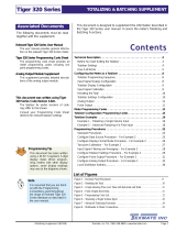
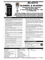
The Tiger 320 Series signal processor and controller has
six setpoints individually programmable to operate within
the total span range of the meter and the selected input
module. A relay output module provides the instrument
with up to six relay outputs using a combination of 5 amp
Form A and 10 amp Form C, or 5 volt solid state relays
(SSRs).
See Relay Options for further details.
All six setpoints are available for relay activation or internal control functions such as
register reset and counting functions. Each setpoint can be individually programmed
to energize a relay or reset a register. The setpoint can be activated from any input
channel, a selected register, or from the rear input pins.
All six setpoints are individually programmable for sophisticated time control applica-
tions using the following features.
SP RESET
➤
➤
➤
➤
Setpoint Activation Source
Setpoints activate from any input channel, selected meter regis-
ter, or external switched inputs (digital input pins).
Setpoint Latching
Setpoints can be programmed in relay latching modes.
➤
Setpoint Reset
Setpoints can be programmed to reset selected registers, or be
manually reset.
Setpoint Tracking
Any setpoint can be programmed to track any other setpoint.

Texmate, Inc.Tel. (760) 598-9899 • www.texmate.com • Setpoints & Relays (NZ201) Page 7
SP Data
Logging
Data Data Data Data Data Data
Data Data Data Data Data Data
Data Data Data Data Data Data
Data Data Data Data Data Data
Data Data Data Data Data Data
Data Data Data Data Data Data
SP
Print
PrintPrint
EPSON
TM-U210
******
******
******
******
*
*
*
*
24:07:00
Job....14322
Job....14322
SP
Deviation
SP
Hysteresis
60
15
30
45
SP TIMER
DUAL PID
SP
➤
➤
➤
➤
➤
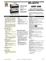
Data Logging
Any setpoint can be programmed to log data within the meter (up
to 4000 samples).
Data Printing to Serial Printer
Any setpoint can be programmed to send data directly to a seri-
al printer.
Data Printing to PC
Any setpoint can be programmed to send data directly to a con-
nected PC.
SP
➤
Hysteresis or Deviation
Each relay can operate in a hysteresis or deviation mode.
PID
Relays 1 and 2 can be programmed for PID operation.
Timer Control Modes
Each setpoint can be programmed to operate the relay in one of
the following seven resident time control modes:
Normal Mode Timer
Single actuation, delay-on-make (DOM) and delay-on-break
(DOB).
Normally OFF/Pulsed ON Timers
Repeat ON Mode Timer – multiple actuation, programmable off-
and on-time.
Pulse ON Mode Timer – single actuation, programmable DOM
and maximum on-time.
1-Shot ON Mode Timer – single actuation, programmable DOM
and minimum on-time.
Normally ON/Pulsed OFF Timers
Repeat OFF Mode Timer – multiple actuation, programmable off-
and on-time.
Pulse OFF Mode Timer – single actuation, programmable DOB
and maximum off-time.
1-Shot OFF Mode Timer – single actuation, programmable DOB
and minimum off-time.

Texmate Inc.Tel. (760) 598-9899 • www.texmate.comPage 8 • Setpoints & Relays (NZ201)
Relay Types: 5 A, 240 VAC Form A, electromechanical relay.
10 A, 240 VAC Form C, electromechanical relay.
400 V, 210 mA DC, independent normally open solid state relay (SSR).
400 V, 140 mA AC / DC, independent normally open SSR.
All Tiger 320 Series meters, except the FI-B101D50, can be configured with a maximum of six electromechani-
cal or four solid state relays (SSRs) using one of the following relay output modules:
Relay Output Module 137: Maximum six 5 A, Form A relays grouped in three using a single
common per group.
Relay Output Module 138: Maximum four relays.Two groups of one 5 A, Form A and one 10 A,
Form C relays using a single common per group.
Relay Output Module 156: Maximum four 5 A, Form A isolated relays.
SSR Output Module 237: Maximum four independent 400 V, 210 mA DC SSRs.
SSR Output Module 241: Maximum four independent 400 V, 140 mA AC / DC SSRs.
GI & FI Meter Main Board: Maximum four relays.Two groups of one 10 A, Form C and one 5 A,
Form A relays sharing a single common per group.
FI Meter Carrier Board: Maximum two independent 400 V, 210 mA DC SSRs.
For further information on relay options for individual meter types, see the specific meter user
manual.
Technical
Specifications
•Any analog input signal on any channel.
•Any digital input signal on any channel.
•Digital input pins at rear of meter.
•An external switch closure.
•Result of math performed on input signal.
•An internal register.
•Serial input.
•Setpoints tracking other setpoints.
Setpoint Activation Source
•Activate ABOVE setpoint.
•Activate BELOW setpoint.
•Hysteresis.
•Deviation.
•Dual PID Control.
•Initial Start-up Inhibit.
•Window Comparator.
Setpoint Activation Functions
•FLASH Display.
•Turn relay ON.
•Turn relay OFF.
•Latch relay ON.
•Latch relay OFF.
•Count setpoint activations.
•Reset any internal register.
•Increment any internal register.
•Activate another relay.
•Print any selected register contents.
•Turn ON front panel annunciators.
•Transfer contents of any register to another register.
•Log data to internal memory.
•Activate a custom macro.
•Send a pulse to an external device.
•Control PID output.
Setpoint Activation Results
Setpoints
& Relays
•Single and multiple actuation, normally OFF / pulsed ON or normally
ON / pulsed OFF modes.
•0.001 second resolution settings for setpoints 1 and 2 in both PULSE
and both REPEAT timer modes.
•0.1 second resolution settings for setpoints 3 to 6 in all timer modes.
•Delay-on-make, Delay-on-break (Normal timer).
•Turn relay ON/OFF/ON/OFF (Repeat timer).
•Turn relay OFF/ON/OFF/ON (–Repeat timer).
•Pulse ON for guaranteed on-time (Pulse timer).
•Pulse OFF for guaranteed off-time (–Pulse timer).
•Stay ON for guaranteed minimum on-time (1Shot timer).
•Stay OFF for guaranteed minimum off-time (–1Shot timer).
Setpoint Timer Results
•Normal Mode.Delay-on-make (DOM), delay-on-break (DOB) settings.
•Repeat ON Mode. Programmable on and off time settings.
•Pulse ON Mode. Programmable DOM and on time settings.
•1-Shot ON Mode. Programmable DOM and minimum on time settings.
•Repeat OFF Mode. Programmable off and on time settings.
•Pulse OFF Mode. Programmable off time and DOB.
•1-Shot OFF Mode. Programmable minimum off time and DOB
settings.
Setpoint Timer Modes

Texmate, Inc.Tel. (760) 598-9899 • www.texmate.com • Setpoints & Relays (NZ201) Page 9
Setpoint & Relay Basic Mode
Level 1
This is an easily programmable mode for users who require the following
basic setpoint and relay functions:
First Digit – Relay Energize Functions
Relays programmed to energize above or below the setpoint value.
Second Digit – SP Activation Source
Setpoints programmed to activate from selectable meter registers or
one of six external switched inputs.
Third Digit – Setpoint Latching
Relays programmed with latching and manual reset options.
Each setpoint can be individually configured for basic to advanced operations in the follow-
ing three levels. Each operational level is designed to provide only the required relevant set-
point and relay functions.
The modes at Level 2 and Level 3 can be set to OFF for each individual setpoint, ensuring
that no other functions are programmed to influence the setup.
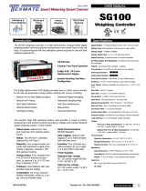
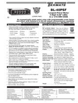
Figure 1 is a block diagram showing the functional blocks that comprise the setpoint mode.
Technical Description
Setpoint & Relay Intermediate Mode
This mode adds extra functionality to the basic mode by providing
programmable hysteresis or deviation settings for all setpoints, or PID
control from setpoints SP1 and SP2.
These modes add even more functionality to the basic and interme-
diate mode by providing each setpoint with a choice of one of seven
resident programmable timers.
Level 2
Timer Modes
Hysteresis, Deviation & PID Mode
Programming Tip
If you do not require any
of the functions in this
mode, ensure it is set to:
Programming Tip
If you do not require any
of the functions in this
mode, ensure it is set to:
Level 2 uses all Level 1 functions and is further extended by the fol-
lowing programmable modes. The functionality of the relay energize
functions are extended by allowing the relays to be programmed with
or without initial start-up inhibit.
Level 3 uses all Level 1 and Level 2 functions combined with reset and
trigger functions to provide an extremely powerful advanced mode.
Level 3 enables you to program all setpoints individually for operations
normally requiring sophisticated controllers.
Level 3 Setpoint & Relay Advanced Mode
Programming Tip
If you do not require any
of the functions in this
mode, ensure it is set to:

Texmate Inc.Tel. (760) 598-9899 • www.texmate.comPage 10 • Setpoints & Relays (NZ201)
Figure 1 – Setpoint Mode Functional Block Diagram
RELAYx
TRIG OFF
SPx_TRIGGER
SETPOINTS
TRIGGERx
SPx_TRIGGER
MODE
TRIGGER FUNCTIONS
SPx_STATUS SPx
SPx_DELAY_TYPE
SPx_HYST
SPx_DELAY_TYPE
SPx_
CO
NTR
OL
ALARM
S
TATU
S
SPx_CONTROL
_
SPx_TRIGGER
SPx_TRIGGER
RELAY_DE_ENERGISE_FLAGS
SPx_RESET_VALUE
SPx_RESET_SOURCE
SPx_RESET_DESTINATION
SPx_BREAK_DELAY
SPx_MAKE_DELAY
OFF
ON
NORMAL
REMOTE
SP
Hysteresis
SP
Deviation
TIMER MODES
S P 1 —
SP6
Pro
g
rammin
g
Ti
p
Programming Tip
SP
SETPOINT_x
SPx_TRACKING
SPx_TRACKING
OFF
ON
SETPOINT
VALUE
SPx_Data_Source
SPT+SETPOINTx
_
_
_

Texmate, Inc.Tel. (760) 598-9899 • www.texmate.com • Setpoints & Relays (NZ201) Page 11
Prog.
SP1 SP2 SP4SP3 SP5 SP6
TEXMATE
FIRST
DIGIT THIRD
DIGIT
SECOND
DIGIT
Setpoint Annunciators
Program
Button DOWN
Button
UP
Button
All Tiger 320 Series meter setpoint and relay functions for Levels 1, 2, and 3 are configured
in the meter’s setpoint programming mode.
During configuration, the last three digits on the meter display are used to select the setpoint
and relay functions. See Figure 2.
Alternately, if the meter is connected to a PC through the serial port, the setpoints can be
configured using the Meter Configuration Program.
See Meter Configuration Utility Program Tutorial (NZ206) for details.
To enter the setpoint programming mode press the meter’s and buttons at the same
time. See Figure 3 – Setpoint Programming Mode Logic Diagram for menu details.
Setpoint Activation Values Mode
On entering the setpoint programming mode, the meter display toggles between [SP_1] and
[18000].This is the Setpoint Activation Values Mode.Using the button, step through each
setpoint and set the activation value required using the and buttons.
Setpoint activation values can be set within the total span range of the meter and the select-
ed input module.
Setpoint and Relay Control Settings Mode
Pressing the button after setting the activation value for SP6 enters the Setpoint and
Relay Control Settings Mode. The meter display toggles between [SPC_1] and [XXX]. This
is the menu for setting setpoint control functions for SP1. Using the button, step through
each setpoint control menu and set the control functions for the required setpoints using the
and buttons.
The setpoint and relay control settings mode provides access to the following setpoint and
relay functions by setting the 1st, 2nd, and 3rd digits on the meter display:
•First Digit – Relay Energize Functions.
Allows you to select the required relay energize functions.
•Second Digit – Setpoint Activation Source.
Allows you to select the setpoint activation source.
•Third Digit – Setpoint Delay, Timer, and Reset and Trigger Functions.
Allows you to select from a range of delays, timers, and reset functions.
Figure 2 shows the front panel of a Tiger 320 Series DI-50 meter.
P
P
P
P
Setpoint Programming
Mode
Figure 2 – Meter Programming Digits for Setpoint and Relay Control Functions

Texmate Inc.Tel. (760) 598-9899 • www.texmate.comPage 12 • Setpoints & Relays (NZ201)
To enter press and
buttons at the same time
P
Setpoint 1
[SP_1]
Setpoint Activation Values Mode
Setpoint 2
[SP_2]
Setpoint 3
[SP_3]
Setpoint 4
[SP_4]
Setpoint 5
[SP_5]
Setpoint 6
[SP_6]
Enter these menus to set setpoint (SP) activation values
Setpoint 1
[SPC_1]
Setpoint & Relay Control Settings Mode
Setpoint 2
[SPC_2]
Setpoint 3
[SPC_3]
Setpoint 4
[SPC_4]
Setpoint 5
[SPC_5]
Setpoint 6
[SPC_6]
Enter these menus to configure SP control values
Setpoint Programming Mode
P
Prog.
Operational Display
SP1 SP2 SP3 SP4 SP5 SP6
P
P
P
P
P
P
P
P
P
P
P
Figure 3 – Setpoint Programming Mode Logic Diagram
See Page 19 for a Level 1 – Setpoint
& Relay Control Settings diagram.
See Page 29 for a Level 2 – Setpoint
& Relay Control Settings diagram.
See Page 55 for a Level 3 – Setpoint
& Relay Control Settings diagram.
Setpoint 1 Default setting = 18000
Default setting = –18000
Default setting = 5000
Default setting = –5000
Default setting = 10000
Default setting = –10000
Prog.
Operational Display
SP1 SP2 SP3 SP4 SP5 SP6

Texmate, Inc.Tel. (760) 598-9899 • www.texmate.com • Setpoints & Relays (NZ201) Page 13
Relay Options Tiger 320 Series DI, FI, and GI meters use the following electromechanical and solid state
relays:
•5 A, 240 VAC Form A, electromechanical relay.
•10 A, 240 VAC Form C, electromechanical relay.
•400 V, 210 mA DC, independent normally open solid state relay (SSR).
•400 V, 140 mA AC / DC, independent normally open SSR.
Order Code
OR45
OR46
Options
SP6 SP5 SP4 SP3 SP2 SP1
5A 5A 5A5A
5A
5A
5A5A5A5A5A
-
32 31 30 2829 27 26 25
DI SeriesSP3 SP2 SP1SP4SP5SP6
Electromechanical Relays
There are three standard electromechanical relay output modules available that use a com-
bination of 5 and 10 A electromechanical relays to make a total of twelve relay options:
•Relay Output Module with Six Non-isolated 5 A Form A Relays.
•Relay Output Module with Two Non-isolated 5 A Form A and 2 Non-isolated 10 A Form C
Relays.
•Four Isolated 5 A Form A Relays
32 31 30 2829 27 26 25
DI Series
Options
5A
5A
Order Code
OR11
OR12
OR23
OR14
-
-
-
-
-
-
-
5A
5A
5A
5A
10A -
-
OR15
OR16
SP2 SP4 SP1 SP3
10A
10A
10A
10A
10A
10A
10A
10A
SP3SP1SP4SP2
Two Non-isolated 5 A Form A & Two Non-isolated 10 A Form C Relays
Six Non-isolated 5 A Form A Relays
This relay output module has a maxi-
mum of two groups of three 5 A Form
A relays using a common pin. There
are a total of two relay combinations
available.
This relay output module has a maxi-
mum of two groups of two relays.Each
group can have a 10 A Form C and 5
A Form A relay using a common pin.
There are a total of six relay combina-
tions available.

Texmate Inc.Tel. (760) 598-9899 • www.texmate.comPage 14 • Setpoints & Relays (NZ201)
32 31 30 2829 27 26 25
DI Series
OptionsOrder Code
OR31
OR32
OR33
OR34
-
-
-
- -
-
5A5A 5A 5A
5A 5A
5A
5A
5A
5A
SP4 SP3 SP2 SP1
SP1SP2SP3SP4
Four Isolated 5 A Form A Relays
Solid State Relays
There are two standard solid state relay (SSR) output modules available that provide a total
of eight relay options:
•Four Independent 400 V, 210 mA (DC Only) SSR Output Module.
•Four Independent 400 V, 140 mA (AC/DC) SSR Output Module.
32 31 30 2829 27 26 25
DI Series
OptionsOrder Code
OR51
OR52
OR53
OR54
-
-
-
- -
-
210mA
210mA
210mA
210mA
210mA
210mA
210mA
210mA
210mA210mA
SP4 SP3 SP2 SP1
SP4 SP3 SP2 SP1
Four Independent 400 V, 210 mA (DC Only) SSR Output Module
32 31 30 2829 27 26 25
DI Series
OptionsOrder Code
OR61
OR62
OR63
OR64
-
-
-
- -
-
140mA
140mA
140mA
140mA
140mA
140mA
140mA
140mA
140mA140mA
SP4 SP3 SP2 SP1
SP4 SP3 SP2 SP1
This SSR output module has a
maximum of four independent, nor-
mally open output, solid state
relays. They are suitable for maxi-
mum 400 V, 140 mA AC/DC inputs.
This relay output module has a
maximum of four isolated 5 A Form
A relays. There are a total of four
relay combinations available.
This SSR output module has a
maximum of four independent, nor-
mally open output, solid state
relays. They are suitable for maxi-
mum 400 V, 210 mA DC inputs only.
Four Independent 400 V, 140 mA (AC/DC) SSR Output Module

Texmate, Inc.Tel. (760) 598-9899 • www.texmate.com • Setpoints & Relays (NZ201) Page 15
Output Module
Carrier Board
Max Six
5 A Form A
Max Two
5 A Form A
Max Two
10 A Form C
Max Four
210 mA
(DC Only)
Max Four
140 mA
(AC/DC)
Max Four
5 A Form A
Output Module
Carrier Board
DI Meter Options GI Meter Options
Main
Processing
Board
FI Meter Options
Main
Processing
Board
Output Module
Carrier Board
Max Two
5 A Form A
Max Two
10 A Form C
Max Four
210 mA
(DC Only)
Max Four
140 mA
(AC/DC)
Max Four
5 A Form A
Max Six
5 A Form A
Figure 4 – Tiger 320 Series Relay Options
Relay Options
All Tiger 320 Series DI and GI meters use plug-in relay output modules. The GI range can
also mount up to four relays in six combinations on its main processor board.
The FI bargraph meter can have up to four electromechanical relays mounted on its main
board and two solid state relays (SSRs) on its output carrier board.
See Figure 4.
Opto-isolators
26
25
Add-on Board
10 Digital Outputs
Standard Board
6 Digital Inputs/6
Digital Outputs
DIN Rail Terminal Block
3M IDC
Cable
An opto-isolated I/O plug-in module is a combination of
two boards that provide a total of six digital status inputs
and 16 digital status outputs using opto-isolators.
The standard board mounts six inputs and six outputs.The
six outputs are controlled by the meter’s six programmable
setpoints.The six inputs operate via a macro.
An add-on board mounts onto the standard board and pro-
vides a further 10 outputs.These also operate via a macro.
The opto-isolators have the following specifications:
•Isolation Voltage: 3.7 kV.
•Collector Emitter: 80 V.
•Collector Current: 50 mA.
1 SP1.
2 SP2.
3 SP3.
4 SP4.
5 SP5.
6 SP6.
Pin Function
Meter setpoints
SP7 to SP16
require a macro
7 SP7.
8 SP8.
9 SP9.
10 SP10.
11 SP11.
12 SP12.
13 SP13.
14 SP14.
15 SP15.
16 SP16.
Pin Function
2
1
The opto-isolated I/O module comes complete
with a 3M IDC cable connected to a DIN rail ter-
minal block. The setpoint external pinouts to the
terminal block are as follows:

Texmate Inc.Tel. (760) 598-9899 • www.texmate.comPage 16 • Setpoints & Relays (NZ201)
FI-B101D50 Bargraph Relays
91011 1312 14 15 16
OptionsOrder Code
R11
R12
R23
R14
-
-
5A
5A
5A
5A 5A
5A
-
-
-
-
R15
R16
SP3 SP1 SP4 SP2
10A
10A
10A
10A
10A
10A
-
-
-
10A
10A
10A
SP1SP3 SP2SP4
PIN Numbers
FI-B101D50 Main / Processor Board
Maximum 2 groups of 1x10 A Form C & 1x5 A Form A Relays
using one common pin per group
The FI-B101D50 bargraph combines
up to two 5 A Form A and two 10 A
Form C electromechanical relays on its
main / processor board. An optional
output carrier board combines two
solid state relays.
The solid state relays are normally
open outputs and are suitable for max-
imum 400 V, 210 mA DC inputs only.
PIN Numbers:
Carrier Board (DC ONLY)
Maximum
2 x 210 mA
400 V DC ONLY
ALL PINS ISOLATED
SSR
31 30 29 28
OptionsOrder Code
R1
R2
-
210mA
210mA
210mA
SP5 SP6
SP5 SP6
GI-50 & GI-50B101 Meter Relays
91011 1312 14 15 16
OptionsOrder Code
R11
R12
R23
R14
-
-
5A
5A
5A
5A 5A
5A
-
-
-
-
R15
R16
SP3 SP1 SP4 SP2
10A
10A
10A
10A
10A
10A
-
-
-
10A
10A
10A
SP1SP3 SP2SP4
PIN Numbers:
GI-50 or GI-50B101 Main / Processor Board
Maximum 2 groups of 1x10 A Form C & 1x5 A Form A Relays
using one common pin per group
The GI-50 and GI-50B101 support
the standard electromechanical and
solid state relay output modules on
their output carrier board. They can
also support up to four electro-
mechanical relays on the main pro-
cessing board.
The relay combination selected for
the main processing board use set-
points 1 to 4. If a plug-in relay output
module with more than two relays is
also selected for the output carrier
board, then both sets of relays desig-
nated SP1 to SP4 share setpoints 1
to 4.

Texmate, Inc.Tel. (760) 598-9899 • www.texmate.com • Setpoints & Relays (NZ201) Page 17
Level 1 – Basic Mode

Texmate Inc.Tel. (760) 598-9899 • www.texmate.comPage 18 • Setpoints & Relays (NZ201)
When configuring each setpoint for Level 1 settings, the following programming sequence
must be followed to ensure that all configuration settings are correctly entered and saved:
Press the and buttons at the same time. This enters the setpoint programming
mode.The display toggles between [SP_1] and [18000].
P
Enter the Setpoint Programming Mode
Use the and buttons to adjust the setpoint 1 (SP1) activation value. If not SP1,
press the button to move to the required setpoint and adjust.
Adjust all other applicable setpoint activation values as required (SP2 to SP6).
P
Adjust Setpoint Activation Values
After all required setpoint activation values have been adjusted, press the button
until [SPC_1] appears.SPC_1 is the setpoint control function programming menu for
setpoint 1.
Set the three digits in the following order:
P
Select Setpoint Control Function Settings
1) 3rd Digit – Turn OFF Intermediate and Advanced Level Modes
Set display to [XX5]
Press the button to enter the Hysteresis, Deviation, & PID Mode sub-
menu. Display toggles between [ModE] and [oFF]. If not set to [oFF], use the
or button to select [oFF].
Set display to [XX6]
Press the button to enter the Timer Mode sub-menu. Display toggles
between [tiMr] and [oFF].If not set to [oFF], use the or button to select [oFF].
Set display to [XX7]
Press the button to enter the Advanced Functions Mode sub-menu.
Display toggles between [triG] and [oFF]. If not set to [oFF], use the or
button to select [oFF].
When complete, reset the third digit to [XX0] to prevent cycling through
the mode.
2) 2nd Digit – Select Setpoint Activation Source
Set to [X1X]
Press the button to enter the sub-menu and select the setpoint activation
source for SP1 from any channel or selected register. When complete, reset
back to [000].
If the SP source is from an external switched input (digital input pin), set to
one of either [X2X] to [X7X] to select the setpoint activation source from one
of six digital inputs (2 to 7).
3) 1st Digit – Select Relay Energize Mode
Select the relay energize mode for SP1 from either [0XX] or [1XX].
4) 3rd Digit – Relay Latching & Manual Reset Functions
Select the 3rd digit setpoint relay latching and manual reset functions either
[XX0] to [XX4] as required.
P
P
P
P
ST
STAR
ART HERE
T HERE
1
2
3
LEVEL 1 – BASIC FUNCTIONS
Programming Tip
As a final setting, combine Steps 3 and 4 to
select the relay energize mode and the
latching and manual reset functions into a
single step.
Level 1 – Relay and
Setpoint Configuration
Sequence

Texmate, Inc.Tel. (760) 598-9899 • www.texmate.com • Setpoints & Relays (NZ201) Page 19
Record all SP1 activation and control values in the Table: Customer Code Settings
– Setpoint Programming Mode on Page 15 of the Tiger 320 Series Programming
Code Sheet (NZ101).
Record All Setpoint Programming Code Settings
Press the button to move to [SPC_2]. SPC_2 is the setpoint control function pro-
gramming menu for setpoint 2 (SP2).
Repeat Steps 3 and 4 for all applicable setpoints.
P
Repeat Setpoint Control Function Settings for all Applicable Setpoints
Press the button to save a setpoint programming mode setting and then press the
and buttons at the same time to return to the operational display.
P
P
Exit the Setpoint Programming Mode
END HERE
END HERE
4
5
6
0 No Latching
1 Relay Latched
2 Manual Relay Reset
3 Relay Latched with Manual
Relay Reset
4 Relay Latched Off
5 -
6 -
7 -
Relay Energize Function
0 Energized ABOVE setpoint
value.
1 Energized BELOW setpoint
value.
2 -
3-
SP Activation Source
0 Activate Setpoint Source from
Selected Register
1 Select Source for Setpoint from Selected
Register
Note:
[X1X] is a register selection procedure
only. To finish, reset to [X0X] to activate
the selection, or reset to 2-7 as required
for digital input selection.
2 Digital Input – Capture Pin
3 Digital Input – D1
4 Digital Input – D2
5 Digital Input – D3
6 HOLD Pin
7 LOCK Pin
SP Delay & Timing Functions
FIRST DIGIT SECOND DIGIT THIRD DIGIT
Level 1 – Setpoint & Relay Control Settings Diagram
Select Source for Setpoint Functions
The following diagram shows the setpoint and relay three digit control function settings for
operational Level 1.
P
[rESLt]
[Ch1]
[Ch2]
[Ch3]
[Ch4] [tot_1] [tot_2]
[PEAK]
[1 to 244]
[tArE]
[VALEY]
[diSP]
Use the
buttons to cycle
through the menu Use the or but-
ton to select a register
as the data source for
the setpoint

Texmate Inc.Tel. (760) 598-9899 • www.texmate.comPage 20 • Setpoints & Relays (NZ201)
SP
SP
Above
Below
ACTIVATION
The 1st digit of the
setpoint and relay con-
trol mode allows you to
configure relay ener-
gize functions.
Level 1 – 1st Digit: Relay Energize Functions
Relay Energize Function
0 Energized ABOVE setpoint value.
1 Energized BELOW setpoint value.
2 -
3-
FIRST DIGIT
[X0X] Activate Setpoint Source from Selected Register
Setting the 2nd digit to 0 [X0X] means that the source selected for the setpoint when the 2nd
digit is set to [X1X] is now active for that setpoint. When selection of the setpoint activation
source in [X1X] is complete, reset back to [X0X].
Also, setting the 2nd and 3rd digits to [X05] to [X07] is the easiest method of entering Level
2 or Level 3 function setup modes.
SP
1SP
2SP
3SP
4SP
5SP
6
Input
Channels
External Switched Inputs
Prog.
SP1 SP2 SP4SP3 SP5 SP6
TEXMATE
The 2nd Digit of the setpoint and relay control mode
allows you to configure the setpoint activation source.
The settings and functionality of the 2nd digit remain the
same for Levels 1, 2, and 3.The activation source must be
programmed for all required setpoints.
The 2nd digit allows you to individually program the acti-
vation source for setpoints 1 to 6 from one of eight selec-
tions. Setpoints activate from any input channel, selected
meter register, or an external switched input (via digital
input pin).
P
[rESLt]
[Ch1]
[Ch2]
[Ch3]
[Ch4] [tot_1] [tot_2]
[PEAK]
[1 to 244]
[tArE]
[VALEY]
[diSP]
SP Activation Source
0 Activate Setpoint Source from
Selected Register (select in 3rd digit)
1 Select Source for Setpoint from Selected
Register
Note:
[X1X] is a register selection procedure
only. To finish, reset to [X0X] to activate
the selection, or reset to 2-7 as required
for digital input selection.
2 Digital Input – Capture Pin
3 Digital Input – D1
4 Digital Input – D2
5 Digital Input – D3
6 HOLD Pin
7 LOCK Pin
SECOND DIGIT
Use the
buttons to cycle
through the menu Use the or but-
ton to select a register
as the data source for
the setpoint
Select Source for Setpoint Functions
To 3rd digit
Level 1 – 2nd Digit: Setpoint Activation Source
Note:
The setpoint activation source of any unused setpoints can be set to off.This improves effi-
ciency and stops unused setpoint activation values being displayed.
Level 1 – Functions
All setpoints activate at the setpoint activation value. At Level 1, the 1st digit allows you to
program the setpoint relay to energize above or below the setpoint value.
/