Page is loading ...

Freescale Semiconductor, Inc.
User’s Guide
© Freescale Semiconductor, Inc., 2015. All rights reserved.
Document Number: KT33978UG
Rev. 2.0, 1/2015
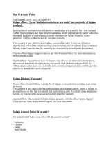
KIT33978EKEVB and KIT34978EKEVB
Evaluation Board
Figure 1. KIT33978EKEVB / KIT34978EKEVB

KT33978UG Rev. 2.0
2 Freescale Semiconductor, Inc.
Contents
1 Important Notice . . . . . . . . . . . . . . . . . . . . . . . . . . . . . . . . . . . . . . . . . . . . . . . . . . . . . . . . . . . . . . . . . . . . . . . . . . . . . . . . . . . . . . . . . . . 3
2 Getting Started . . . . . . . . . . . . . . . . . . . . . . . . . . . . . . . . . . . . . . . . . . . . . . . . . . . . . . . . . . . . . . . . . . . . . . . . . . . . . . . . . . . . . . . . . . . . 4
3 Getting to Know the Hardware . . . . . . . . . . . . . . . . . . . . . . . . . . . . . . . . . . . . . . . . . . . . . . . . . . . . . . . . . . . . . . . . . . . . . . . . . . . . . . . . 5
4 Accessory Interface Board . . . . . . . . . . . . . . . . . . . . . . . . . . . . . . . . . . . . . . . . . . . . . . . . . . . . . . . . . . . . . . . . . . . . . . . . . . . . . . . . . . 10
5 Installing the Software and Setting up the Hardware . . . . . . . . . . . . . . . . . . . . . . . . . . . . . . . . . . . . . . . . . . . . . . . . . . . . . . . . . . . . . . 11
6 Schematic. . . . . . . . . . . . . . . . . . . . . . . . . . . . . . . . . . . . . . . . . . . . . . . . . . . . . . . . . . . . . . . . . . . . . . . . . . . . . . . . . . . . . . . . . . . . . . . 17
7 Board Layout. . . . . . . . . . . . . . . . . . . . . . . . . . . . . . . . . . . . . . . . . . . . . . . . . . . . . . . . . . . . . . . . . . . . . . . . . . . . . . . . . . . . . . . . . . . . . 18
8 Bill of Materials . . . . . . . . . . . . . . . . . . . . . . . . . . . . . . . . . . . . . . . . . . . . . . . . . . . . . . . . . . . . . . . . . . . . . . . . . . . . . . . . . . . . . . . . . . . 19
9 References . . . . . . . . . . . . . . . . . . . . . . . . . . . . . . . . . . . . . . . . . . . . . . . . . . . . . . . . . . . . . . . . . . . . . . . . . . . . . . . . . . . . . . . . . . . . . . 20
10 Revision History . . . . . . . . . . . . . . . . . . . . . . . . . . . . . . . . . . . . . . . . . . . . . . . . . . . . . . . . . . . . . . . . . . . . . . . . . . . . . . . . . . . . . . . . . 21

Important Notice
KT33978UG Rev. 2.0
Freescale Semiconductor, Inc. 3
1 Important Notice
Freescale provides the enclosed product(s) under the following conditions:
This evaluation kit is intended for use of ENGINEERING DEVELOPMENT OR EVALUATION PURPOSES ONLY.
It is provided as a sample IC pre-soldered to a printed circuit board to make it easier to access inputs, outputs, and
supply terminals. This evaluation board may be used with any development system or other source of I/O signals
by simply connecting it to the host MCU or computer board via off-the-shelf cables. This evaluation board is not a
Reference Design and is not intended to represent a final design recommendation for any particular application.
Final device in an application will be heavily dependent on proper printed circuit board layout and heat sinking
design as well as attention to supply filtering, transient suppression, and I/O signal quality.
The goods provided may not be complete in terms of required design, marketing, and or manufacturing related
protective considerations, including product safety measures typically found in the end product incorporating the
goods. Due to the open construction of the product, it is the user's responsibility to take any and all appropriate
precautions with regard to electrostatic discharge. In order to minimize risks associated with the customers
applications, adequate design and operating safeguards must be provided by the customer to minimize inherent or
procedural hazards. For any safety concerns, contact Freescale sales and technical support services.
Should this evaluation kit not meet the specifications indicated in the kit, it may be returned within 30 days from the
date of delivery and will be replaced by a new kit.
Freescale reserves the right to make changes without further notice to any products herein. Freescale makes no
warranty, representation or guarantee regarding the suitability of its products for any particular purpose, nor does
Freescale assume any liability arising out of the application or use of any product or circuit, and specifically
disclaims any and all liability, including without limitation consequential or incidental damages. “Typical” parameters
can and do vary in different applications and actual performance may vary over time. All operating parameters,
including “Typical”, must be validated for each customer application by customer’s technical experts.
Freescale does not convey any license under its patent rights nor the rights of others. Freescale products are not
designed, intended, or authorized for use as components in systems intended for surgical implant into the body, or
other applications intended to support or sustain life, or for any other application in which the failure of the Freescale
product could create a situation where personal injury or death may occur.
Should the Buyer purchase or use Freescale products for any such unintended or unauthorized application, the
Buyer shall indemnify and hold Freescale and its officers, employees, subsidiaries, affiliates, and distributors
harmless against all claims, costs, damages, and expenses, and reasonable attorney fees arising out of, directly or
indirectly, any claim of personal injury or death associated with such unintended or unauthorized use, even if such
claim alleges Freescale was negligent regarding the design or manufacture of the part.Freescale™ and the
Freescale logo are trademarks of Freescale Semiconductor, Inc. All other product or service names are the property
of their respective owners. © Freescale Semiconductor, Inc. 2015

Getting Started
KT33978UG Rev. 2.0
4 Freescale Semiconductor, Inc.
2 Getting Started
2.1 Kit Contents/Packing List
The KIT33978EKEVB / KIT34978EKEVB contents include:
• Assembled and tested evaluation board/module in anti-static bag.
• Warranty card
2.2 Jump Start
Freescale’s analog product development boards help to easily evaluate Freescale products. These tools support analog mixed signal and
power solutions including monolithic ICs using proven high-volume SMARTMOS mixed signal technology, and system-in-package devices
utilizing power, SMARTMOS and MCU dies. Freescale products enable longer battery life, smaller form factor, component count reduction,
ease of design, lower system cost and improved performance in powering state of the art systems.
•Go to www.freescale.com/analogtools
• Locate your kit
• Review your Tool Summary Page
• Look for
• Download documents, software and other information
Once the files are downloaded, review the user guide in the bundle. The user guide includes setup instructions, BOM and schematics.
Jump start bundles are available on each tool summary page with the most relevant and current information. The information includes
everything needed for design.
2.3 Required Equipment and Software
To use this kit, you need:
• Power supply 12 V with at least 1.0 A current capability
• ON-OFF switch to Ground or Switch to Battery loads
• KITUSBSPIDGLEVME communication dongle
• SPIGen Graphic User Interface
2.4 System Requirements
The kit requires the following to function properly with the software:
• Windows® XP, Windows 7, or Vista in 32- and 64-bit versions
Jump Start Your Design

Getting to Know the Hardware
KT33978UG Rev. 2.0
Freescale Semiconductor, Inc. 5
3 Getting to Know the Hardware
3.1 Board Overview
The KIT33978EKEVB and KIT34978EKEVB Evaluation Board (EVB) features the MC33978 / MC34978 - 22 Channel Switch Detection
Interface with programmable wetting current. The kit is designed to detect the closing and opening of up to 22 switch contacts. The switch
status, either open or closed, is transferred to the microprocessor unit (MCU) through a serial peripheral interface (SPI). The device also
features a 24-to-1 analog multiplexer for reading inputs as analog.
The analog input signal is buffered and provided on the AMUX output pin to be read by an external MCU.The MC33978 / MC34978 device
has two modes of operation, Normal and Sleep. Normal Mode allows programming of the device and supplies switch contacts with pull-up
or pull-down current as it monitors switch change-of-state, while the sleep mode provide switch status detection with maximum power
saving.
The KIT33978EKEVB / KIT34978EKEVB can be controlled through a USB/SPI dongle (KITUSBSPIDGLEVME) connected to the PC’s
USB port. The Freescale SPIGen (version 7.0 and above) program provides the user interface to the MC33978 / MC34978 SPI port and
allows the user to program the configuration Registers, send commands to the IC and receive status from the IC.
3.2 Board Features
The board features are as follows:
• MC33978 / MC34978 device with 22 channels switch detection and status report capability
• An onboard 16-pin interface connector for the Freescale SPI-to-USB Interface Dongle (KITUSBSPIDGLEVME)
• Status LEDs to report the status of the MC33978 and MC34978 Interrupt (INT) and Wake-Up lines
• Double row, 100mils SGx/SPx pin connectors for easy interface with external loads
• Direct connection to Batter power with optional 5.0 V/3.3 V LDO for VDDQ rail supply

Getting to Know the Hardware
KT33978UG Rev. 2.0
6 Freescale Semiconductor, Inc.
3.3 Board Description
The KIT33978EKEVB / KIT34978EKEVB is divided in three main sections as shown in Figure 2.
• Input Power supply
• Switch detection Interface
• SPI communication interface
Figure 2. KIT33978EKEVB / KIT34978EKEVB Board Description
Table 1. Board Description
Name Description
Input Power supply
The input power supply provides direct connection to battery voltage which serve as the source for VBATP
supply for the MC33978 / MC34978 and all other configurations that may required to be connected to this
voltage rail.
It also provide the footprint for an optional LDO regulator to generate VDDQ supply internally out of the battery
voltage.
Switch Detection Interface
The switch detection interface include the MC33978 / MC34978 device itself, as well as the configuration
jumpers, and test points to provide easy access to all pins on this device.
It also provide 2 I/O connectors (SV3 and SV4) to provide direct access to the SG and SP pins.
SPI communication interface
The SPI communication interface includes a 16-pin header prepared to interface with the SPI Dongle
(KITUSBSPIDGLEVME).
C26
C31
C32 C33 C34
C35
C36
C37
C38
C39
C40
C41
C42
C43
C44
C45 C46 C47
C48
C49
C50
C51
C52
PWB-700-28220
2013 FREESCALE
U1
1
3
4
1
2
1
1
16
1
26
1
26
123
12
BAT
GND
KIT33978EKEVB
Rev C
PWA-170-28220
CS_B
MISO
MOSI
SCLK
AMUX
GND
GND
GND
VDDQ
5v
3.3v
SG5
BAT
MC33978EK
SG5
Connector
1
C1C2C3C4C5C6
C7 C8 C9 C10 C11 C12 C13
C14C15C16C17
C18 C19 C20 C21
R1R2R3R4
R5 R6 R7 R8
R9R10R11R12R13R14R15
R16 R17 R18 R19 R20 R21 R22
C22
R23
R24
R25
R26
R27
R29
C23
SV1
R30
R31
R32
U4
LED1
INT_B
WAKE_B
R33
D1
R34
U5
SJ1
SJ2
VDDQ
JP2
C24
C25
C27
C28
C29
R36
R37
AMUX
JP3
C30
CS_B
SCLK
MISO
MOSI
VBATP
SV5
JP4
JP1
JP5
SV2
GND
WAKEB
INTB
C53
C54
SV3
SV4
JP7
X7
WAKE_B
VBATP
VDDQ

Getting to Know the Hardware
KT33978UG Rev. 2.0
Freescale Semiconductor, Inc. 7
3.4 LED Display
The following LEDs are provided as visual indicators for the KIT33978EKEVB / KIT34978EKEVB evaluation board:
1. LED1: When JP3 is shorted, LED1 indicates the presence of battery voltage on connector X7.
2. WAKE_B LED: When external pull-up is selected on SV1,the LED lights when the device is in Normal mode.
3. INT_B LED: When JP2 is shorted, the LED lights up when an interrupt even has occurred. LED turns off when the INTflg is
cleared.
3.5 Connectors
The KIT33978EKEVB and KIT34978EKEVB provides various connectors to supply power, interface with programming logic or interface
with the switch loads.
Table 2. Connectors
Name Type Description
X7 Supply Battery supply connector
SV2
I/O interface
(SPI Dongle)
SPI dongle interface connector
Note: Pins are mirrored compared to the connector on the SPI dongle board. Use a straight
through flat ribbon cable to interface with the KIT33978EKEVB and KIT34978EKEVB.
PIN1= SG1
PIN3 = SG2
PIN5 = SG3I
PIN7 = INT_B
PIN9 = WAKE_B
PIN11 = Unused
PIN13 = Unused
PIN15 = AMUX
PIN2 = CS_B
PIN4 = MISO
PIN6 = MOSI
PIN8 = SCLK
PIN10 = UNUSED
PIN12 = SPI Dongle 5.0 V
PIN14 = SPI Dongle 3.3 V
PIN16 = AGND
SV3 I/O interface
Switch detect channel interface connector
(Odd pins connect directly to MC33978 / MC34978 pin, even pins connect to the same node
through a 100 Ω resistor.)
Pin 1 and 2 = BATTERY voltage
Pin 3 = SG6 --> 100 ohm --> Pin 4 = SG6R
Pin 5 = SG5 --> 100 ohm --> Pin 6 = SG5R
Pin 7 = SG4 --> 100 ohm --> Pin 8 = SG4R
Pin 9 = SG3 --> 100 ohm --> Pin 10 = SG3R
Pin 11 = SG2 --> 100 ohm --> Pin 12 = SG2R
Pin 13 = SG1 --> 100 ohm --> Pin 14 = SG1R
Pin 15 = SG0 --> 100 ohm --> Pin 16 = SG0R
Pin 17 = SP3 --> 100 ohm --> Pin 18 = SP3R
Pin 19 = SP2 --> 100 ohm --> Pin 20 = SP2R
Pin 21 = SP1 --> 100 ohm --> Pin 22 = SP1R
Pin 23 = SP0 --> 100 ohm --> Pin 24 = SP0R
Pin 25 and 26 = GND
SV4 I/O interface
Switch detect channel interface connector
(Odd pins connect directly to MC33978 / MC34978 pin, even pins connect to the same node
through a 100 Ω resistor.)
Pin 1 and 2 = BATTERY voltage
Pin 3 = SP7 --> 100 ohm --> Pin 4 = SP7R
Pin 5 = SP6 --> 100 ohm --> Pin 6 = SP6R
Pin 7 = SP5 --> 100 ohm --> Pin 8 = SP5R
Pin 9 = SP4 --> 100 ohm --> Pin 10 = SP4R
Pin 11 = SG13 --> 100 ohm --> Pin 12 = SG13R
Pin 13 = SG12 --> 100 ohm --> Pin 14 = SG12R
Pin 15 = SG11 --> 100 ohm --> Pin 16 = SG11R
Pin 17 = SG10 --> 100 ohm --> Pin 18 = SG10R
Pin 19 = SG9 --> 100 ohm --> Pin 20 = SG9R
Pin 21 = SG8 --> 100 ohm --> Pin 22 = SG8R
Pin 23 = SG7 --> 100 ohm --> Pin 24= SG7R
Pin 25 and 26 = GND

Getting to Know the Hardware
KT33978UG Rev. 2.0
8 Freescale Semiconductor, Inc.
Figure 3. Connector Locations
3.6 Test Point Definitions
The following test points provide access to signals on the MC33978 and MC34978 IC.
Table 3. Test Point Definitions
Schematic Label Description
VBATP Supply Voltage
VDDQ Logic Supply Voltage
INTB I/O Interrupt pin
WAKEB I/O Wake up pin
AMUX Analog Multiplexer output pin
SCLK SPI serial Clock
MOSI SPI Master out - Slave in
MISO SPI Master In - Slave Out
CS_B SPI Chip select
GND 4 x ground reference

Getting to Know the Hardware
KT33978UG Rev. 2.0
Freescale Semiconductor, Inc. 9
3.7 Jumper Definitions
The following table defines the evaluation board jumper positions and explains their functions.
Figure 4. Default Jumper Configuration
Table 4. Jumper Definition
Name Default Description
JP1 Open INT_B LED Bypass jumper (short to bypass LED)
JP2 Close INT_B external pull-up enable. (short to enable the External pull-up to VDDQ)
JP3 Close Battery Voltage LED. Short to enable LED indicator when Battery is connected on X7
JP4 Close
Battery supply jumper. Short to allow voltage on X7 to supply the KIT33978EKEVB and
KIT34978EKEVB board
JP5 Open WAKE_B LEDE bypass jumper. (short to bypass the LED)
JP7 2-3
SG5 input selector.
Short position 1-2 to connect SG5 to Battery voltage
Short position 2-3 to allow SG5 input from connector SV3
SV1 1-2
WAKE_B pull up selector
Short position 1-2 to select VBATP as pull-up voltage
Short position 2-3 to select VDDQ as pull-up voltage
SV5 2-3
VDDQ supply selector from SPI dongle connector
Short position 1-2 for 3.3 V VDDQ supply
Short position 2-3 for 5.0 V VDDQ supply

Accessory Interface Board
KT33978UG Rev. 2.0
10 Freescale Semiconductor, Inc.
4 Accessory Interface Board
The KIT33978EKEVB and KIT34978EKEVB may be used with the KITUSBSPIDGLEVME interface dongle, which provides a USB-to-SPI
interface. This small board makes use of the USB, SPI and parallel ports built into Freescale’s MC68HC908JW32 microcontroller. The
main function provided by this dongle is to allow Freescale evaluation kits having a parallel port to communicate via a USB port to a PC.
Figure 5. KITUSBSPIDGLEVME Interface Dongle
4.1 Connecting the KITUSBSPIDGLEVME Interface Dongle
A typical connection of KITUSBSPIDGLEVME Interface Dongle to the KIT33978EKEVB and KIT34978EKEVB evaluation board is done
through a straight through flat ribbon cable from the IO PORT connector on the SPI Dongle to connector SV2 on the KIT33978EKEVB
and KIT34978EKEVB board.
Figure 6. Connecting KITUSBSPIDGLEVME to the Evaluation Board
Table 5. KITUSBSPIDGLEVME I/O Port plus KIT33978EKEVB / KIT34978EKEVB SV2 Pin Definitions
KIT33978EKEVB and KIT34978EKEVB KITUSBSPIDGLEVME
Pin Number Name Pin Number Name Description
2 CS_B 1 CSB SPI signal, Chip Select Bar
1 SG1 2 CNTL2 CNTL2 connected to SG1
4 MISO 3 SO SPI signal, Serial Out
3 SG2 4 CNTL1 CNTL1 connected to SG2
6 MOSI 5 SI SPI signal, Serial In
5 SG3 6 CNTL0 CNTL0 connected to SG3
8 SCLK 7 SCLK SPI signal, Serial Clock
7 INT_B 8 DATA4 DATA4 connected to INT_B
10 UNUSED 9 CNTL3 NC
9 WAKE_B 10 DATA3 DATA3 connected to WAKE_B
12 5V 11 VDD +5.0 Volt VDD from USB
11 UNUSED 12 DATA2 NC
14 3.3V 13 +3.3 V +3.3 V from USB
13 UNUSED 14 DATA1 NC
16 GND 15 GND Signal Ground
15 AMUX 16 DATA0 DATA0 connected to AMUX

Installing the Software and Setting up the Hardware
KT33978UG Rev. 2.0
Freescale Semiconductor, Inc. 11
5 Installing the Software and Setting up the Hardware
5.1 Installing SPIGen Freeware on your Computer
The latest version of SPIGen is designed to run on any Windows 8, Windows 7, Vista, or XP-based operating system. To install the
software, go to
www.freescale.com/analogtools and select your kit. Click on the link to open the corresponding Tool Summary Page. Look
for “Jump Start Your Design”. Download to your computer desktop the SPIGen software. Run the install program from the desktop. The
Installation Wizard guides you through the rest of the process.
To use SPIGen, go to the Windows Start menu, then Programs, then SPIGen, and click on the SPIGen icon. The SPIGen Graphic User
Interface (GUI) appears. The GUI provide embedded support for some Freescale devices, eliminating the need of loading a configuration
file to talk to an specific device. The MC33978 / MC34978 is already supported by the latest SPIGen software. Locate the MC33978 /
MC34978 folder from the “Device View” window, and click on it to expand and get access to all the configuration registers for the MC33978
/ MC34978 device.
Figure 7. SPIGen GUI

Installing the Software and Setting up the Hardware
KT33978UG Rev. 2.0
12 Freescale Semiconductor, Inc.
5.2 Describing the GUI Interface
The SPIGen GUI is divided into three major sections:
1. Device View: provide a list of supported devices embedded into the SPIGen software.
2. Command window: provide access to all the functions and commands contained in each one of the command pages for the
MC33978 / MC34978.
3. SPI Words window: provide the latest SPI word sent and received in RAW format (32 bits).
5.3 Using the GUI Interface
Before starting the communication with the KIT33978EKEVB / KIT34978EKEVB, it is important to understand the Full Duplex nature of
the SPI communication protocol.
During each SPI clock cycle, a full duplex data transmission occurs:
• the master sends a bit on the MOSI line; the slave reads it from that same line
• the slave sends a bit on the MISO line; the master reads it from that same line
Not all transmissions require all four of these operations to be meaningful, but they do happen.
This means that when the master sends a configuration command [A] through the MOSI pin, the actual data received on the MISO pin is
the value for the transaction made in the previous SPI request, which in turns means that the user sees the result to the command [A] on
the MISO response of the next SPI transaction [B] as depicted in Figure 8.
Figure 8. Full Duplex SPI transaction example.
Due to the Full Duplex nature of the protocol, when using the SPIGen GUI, the user should send the command twice in order to see the
actual response to the request sent.
MOSI/
SCLK
MISO
Control word [A] Configure word [A]
31 24252627282930 23 0122
Previous command data
21 23
20
...
Previous Address
CS_B
MISO
31 24252627282930 23 0122
Response Word [A]
21 23
20
...
Control Word [A]
MOSI/
SCLK
Control word [B] Configure words [B]
CS_B

Installing the Software and Setting up the Hardware
KT33978UG Rev. 2.0
Freescale Semiconductor, Inc. 13
5.3.1 Reading/Writing a SPI register
The MC33978 and MC34978 SPI register map is formed by 30 Functional registers that can be Read only, Write only or Read and Write.
For more detail on the organization and register definition, refer to the MC33978 / MC34978 Data Sheet. The SPIGen GUI provides a
friendly way to configure and read each one of the registers.
To write a configuration register / command:
• Click on the corresponding command page
• Highlight the Register bits to set the register to 1 or clear to set to 0 or select the pre-defined configuration options if available.
• Click the “Write” button to send the SPI command
Figure 9. Register SPI Write
To read the value of a specific register, click the “Read” button twice, and the current value is populated on the Raw Register bits.
The SPIGen GUI allows to write or read on registers according to its proper function, therefore, if a register is Read only, SPIGen does
not provide a predefined way to write into that register.
Figure 10 shows the Read Status Register, which is an example of a read only
register on the MC33978 and MC34978, therefore SPIGen provides only the “Read” button.
Figure 10. Read only Register example
Register Bits
Available Pre-define configuration

Installing the Software and Setting up the Hardware
KT33978UG Rev. 2.0
14 Freescale Semiconductor, Inc.
5.3.2 Creating Sequential Scripts
The SPIGen GUI provides a way to create, save, and load scripts with a sequence of commands for quick configuration. To add commands
to the “sequential command” page, set the configuration bits as desired and click on the “>Seq” button. The corresponding configuration
is added to the “Sequential commands” in the order they are entered as shown in Figure 11.
Figure 11. Sequential Command Page
The sequential script page allows to organize and create various functions within the script by using the following buttons.
• Insert Wait: Insert a defined delay before the next command.
• Remove Selected line: Delete the selected line from the script.
• Move Up/Down: Shift the selected command one place up or down.
• Clear List: Delete all lines from the script window.
• Insert Data 0 Toggle: Not Used on KIT33978EKEVB / KIT34978EKEVB
• Run: Start the script run as a single or loop sequence.
• Loop: Enable the looping sequence mode to repeat the script indefinitely.
• Stop: Stops the script before it is over.
• Save: save the current configuration into a .txt file.
• Load: load a previous configuration from a file.
5.3.3 Sending Customize SPI commands
The SPIGen GUI allows the sending of customized 32-bit SPI words for debugging or any other special use with the MC33978 and
MC34978.
• From Generic folder in the Device View, select the Single command page.
• Chose the 32-bit length and chose the format preference. (binary or Hex)
• Set the bits high or low as desired.
• Click the “Send Once” or “Send Continuously” button to send the selected word through SPI.

Installing the Software and Setting up the Hardware
KT33978UG Rev. 2.0
Freescale Semiconductor, Inc. 15
Figure 12. Generic Single command Page
The “SPI word Session Log” frame, shows the history of commands sent.
The “Extra pins” section allows to set high or low the extra control/data I/Os provided in the IO Port of the KITUSBSPIDGLEVME. Refer
to
Table 5 for the pin to pin correlation between the interface connector on both KITUSBSPIDGLEVME and KIT33978EKEVB /
KIT34978EKEVB boards. Note that not all signals may be usable as input or output with the KIT33978EKEVB and KIT34978EKEVB. Make
sure you understand each pin function on the MC33978 / MC34978 before applying a high or low to these pins.
Finally, the “Quick Commands” section allow the user to create customized commands and the commands are saved for further quick
access during the current session. To save a quick command, set the 32-bit word you want to save, write a name on the header frame,
and then click the “Save” button. The new commands added are listed below the header frame.

Installing the Software and Setting up the Hardware
KT33978UG Rev. 2.0
16 Freescale Semiconductor, Inc.
5.4 Configuring the Hardware
Figure 13 shows the configuration diagram for the KIT33978EKEVB / KIT34978EKEVB.
Figure 13. KIT33978EKEVB / KIT34978EKEVB plus KITUSBSPIDGLEVME Board Setup
5.4.1 Step-by-step Instructions for Setting up the Hardware using SPIGen
To start working with the KIT33978EKEVB / KIT34978EKEVB, the following connections and setup must be performed:
1. Install the SPIGen.
2. Connect KITUSBSPIDGLEVME to the computer and to the KIT33978EKEVB / KIT34978EKEVB evaluation board.
3. Attach DC power supply (without turning on the power) to KIT33978EKEVB / KIT34978EKEVB.
4. Attach loads to the KIT33978EKEVB / KIT34978EKEVB board output terminals as desired.
5. Launch SPIGen and select the MC33978 command page.
6. Turn on the power supply. LED1 lights up.
7. Send a command on the SPIGen software and make sure you get a valid response on the SPI Word Received.
8. Go to the Tri-state page and clear all SG/SP bits.
9. If switch load to ground/battery are attached, change the status of the switches and read the status register to verify whether
the MC33978 / MC34978 is detecting the switch status change.
• When a change of status is detected on a channel, the INT_B LED should light up. The LED turns off when the status register
is read.
USB/SPI Dongle
(KITUSBSPIDGLEVME)
16-Pin SPI Ribbon
Cable
Power Supply
GND
BATTERY
KIT33978EKEVB / KIT34978EKEVB
22 Channel Switch Detection Interface
with programmable wetting current

Schematic
KT33978UG Rev. 2.0
Freescale Semiconductor, Inc. 17
6 Schematic
Figure 14. Evaluation Board Schematic
AGND
AGND
100nF
100nF
100nF
100nF
100nF
100nF
100nF
100nF
100nF
100nF
100nF
100nF
100nF
100nF
100nF
100nF
100nF
100nF
100nF
100nF
100nF
AGND
100nF
1nF
AGND
32V
GREEN
AGND
ES3AX
NCV8664-D
100uF
100uF 100nF 1nF
10uF 100nF
50pF
AGND
1nF
1nF
1nF
1nF
1nF
1nF
1nF
1nF
1nF
1nF
1nF
1nF
1nF
1nF
1nF
1nF
1nF
1nF
1nF
1nF
1nF
1nF
AGND
AGND
AGND
100nF
1nF
Battery ON
Before Resistor
After Resistor
Needed for NI SPI box.
Notes:
Capacitors for EMC / ESD.
Plan to DNP, use as needed.
Rev B
New Power Connector
U1
MC33978
GND
1
MOSI
2
SCLK
3
CS_B
4
SP0
5
SP1
6
SP2
7
SP3
8
SG0
9
SG1
10
SG2
11
SG3
12
SG4
13
SG5
14
SG6
15
VBATP
16
WAKE_B
17
SP4
25
SG13
24
SG12
23
SG11
22
SG10
21
SG9
20
SG8
19
SG7
18
SP5
26
SP6
27
SP7
28
INT_B
29
AMUX
30
VDDQ
31
MISO
32
EP
P$1*30
C1
C2
C3
C4
C5
C6
C7
C8
C9
C10
C11
C12
C13
C14
C15
C16
C17
C18
C19
C20
C21
R1
R2
R3
R4
R5
R6
R7
R8
R9
R10
R11
R12
R13
R14
R15
R16
R17
R18
R19
R20
R21
R22
C22
R23
R24
R25
R26
R27
R29
C23
SV1
1
2
3
R30
R31
R32
U4
LED1
INT_B
WAKE_B
R33
D1
R34
1
2
3
U5SJ1
21
SJ2
21
VDDQ
JP2
1
2
C24
C25
C26 C27
C28 C29
R36
R37
AMUX
JP3
1
2
C30
CS_B
SCLK
MISO
MOSI
VBATP
SV5
1
2
3
JP4
1
2
C31
C32
C33
C34
C35
C36
C37
C38
C39
C40
C41
C42
C43
C44
C45
C46
C47
C48
C49
C50
C51
C52
JP1
1
2
JP5
1
2
SV2
1
3
5
2
4
6
7
9
8
10
11
13
15
12
14
16
GND
GND1
GND2
GND3
WAKEB
INTB
C53C54
SV3
1
3
5
2
4
6
7
9
8
10
11
13
15
12
14
16
17
19
18
20
21
23
25
22
24
26
SV4
1
3
5
2
4
6
7
9
8
10
11
13
15
12
14
16
17
19
18
20
21
23
25
22
24
26
JP7
1
2
3
X7-1
X7-2
SG13
SG13
SG13
SG12
SG12
SG12
SG11
SG11
SG11
SG10
SG10
SG10
SG9
SG9
SG9
SG8
SG8
SG8
SG7
SG7
SG7
SG6
SG6
SG6
SG5
SG5
SG5
SG4
SG4
SG4
SG3
SG3
SG3
SG3
SG2
SG2
SG2
SG2
SG1
SG1
SG1
SG1
SG0
SG0
SG0
SP7
SP7
SP7
SP6
SP6
SP6
SP5
SP5
SP5
SP4
SP4
SP4
SP3
SP3
SP3
SP2
SP2
SP2
SP1
SP1
SP1
SP0
SP0
SP0
VBATP
VBATP
WAKE_B
WAKE_B
WAKE_B
INT_B
INT_B
INT_B
VDDQ
VDDQ
VDDQ
VDDQ
VDDQ
CS_B
CS_B
CS_B
SCLK
SCLK
MOSI
MOSI
MISO
MISO
AGND AGND
AGND
AGND AGND
SP7R
SP7R
SP1R
SP1R
SP6R
SP6R
SP0R
SP0R
SG13R
SG13R
SG12R
SG12R
SG11R
SG11R
SG10R
SG10R
SG9R
SG9R
SG8R
SG8R
SG7R
SG7R
SG6R
SG6R
SG5R
SG5R
SG5R
SG4R
SG4R
SG3R
SG3R
SG2R
SG2R
SG1R
SG1R
SG0R
SG0R
CS_B_
MISO_
MOSI_
SCLK_
SP5R
SP5R
SP4R
SP4R
SP3R
SP3R
BATTERY
BATTERY BATTERY
BATTERY BATTERY
5OR3P3
SP2R
SP2R
D5V
D5V
D3P3V
D3P3V
SG5RJ
SG5RJ

Board Layout
KT33978UG Rev. 2.0
18 Freescale Semiconductor, Inc.
7 Board Layout
Figure 15. Evaluation Board Layout
C26
C31
C32 C33 C34
C35
C36
C37
C38
C39
C40
C41
C42
C43
C44
C45 C46 C47
C48
C49
C50
C51
C52
PWB-700-28220
2013 FREESCALE
U1
1
3
4
1
2
1
1
16
1
26
1
26
123
12
BAT
GND
KIT33978EKEVB
Rev C
PWA-170-28220
CS_B
MISO
MOSI
SCLK
AMUX
GND
GND
GND
VDDQ
5v
3.3v
SG5
BAT
MC33978EK
SG5
Connector
1
C1C2C3C4C5C6
C7 C8 C9 C10 C11 C12 C13
C14C15C16C17
C18 C19 C20 C21
R1R2R3R4
R5 R6 R7 R8
R9R10R11R12R13R14R15
R16 R17 R18 R19 R20 R21 R22
C22
R23
R24
R25
R26
R27
R29
C23
SV1
R30
R31
R32
U4
LED1
INT_B
WAKE_B
R33
D1
R34
U5
SJ1
SJ2
VDDQ
JP2
C24
C25
C27
C28
C29
R36
R37
AMUX
JP3
C30
CS_B
SCLK
MISO
MOSI
VBATP
SV5
JP4
JP1
JP5
SV2
GND
WAKEB
INTB
C53
C54
SV3
SV4
JP7
X7
WAKE_B
VBATP
VDDQ

Bill of Materials
KT33978UG Rev. 2.0
Freescale Semiconductor, Inc. 19
8 Bill of Materials
Table 6. Bill of Materials
(1)
Item Qty Schematic Label Value Description Part Number
Assy
Opt
Active Components
11U1 -
22 Channel Switch Detection
Interface SOIC32
MC33978EK/
MC34978EK
(2)
2 1 U4 32 V Varistor CN1812
(3)
3 1 U5 - 3.3 V or 5.0 V LDO - SOT223 NCV8664
(3)
Diodes
41D1 -
RECTIFIER, FAST, 3 A, 50 V,
DO-214AB, Diode
ES3A
5 1 LED1 - 0805 Green LED
6 2 INT_B, WAKE_B - 0805 Red LED
Capacitors
725
C1, C2, C3, C4, C5, C6, C7, C8, C9, C10,
C11, C12, C13, C14, C15, C16, C17, C18,
C19, C20, C21, C22, C26, C29, C53
100 nF 0805 100 nF capacitor 50 V
8 2 C24, C25 100 uF Electrolythic capacitor Radial
9 1 C28 10 uF 1210 10 uF capacitor 10 V
10 22
C31, C32, C33, C34, C35, C36, C37, C38,
C39, C40, C41, C42, C43, C44, C45, C46,
C47, C48, C49, C50, C51, C52
1 nF 0603 1 nF capacitor
(3)
11 3 C23, C27, C54 1 nF 0805 1 nF capacitor
12 1 C30 50 pF 0805 50 pF capacitor
Resistors
13 2 SJ1, SJ2 0 Ω 0805 0 Ω shunt resistor
14 4 R24, R25, R26, R27, 0 Ω 0603 0 Ω resistor
15 6 R23, R30, R31, R32, R37, R36 0 Ω 0603 0 Ω resistor
(3)
16 1 R29 10 KΩ 0805 10 KΩ Resistor
17 2 R33, R34 1.0 KΩ 0805 1 KΩ resistor
18 22
R1, R2, R3, R4, R5, R6, R7, R8, R9, R10,
R11, R12, R13, R14, R15, R16, R17, R18,
R19, R20, R21, R22
50 Ω 0805 50 Ω resistor
Switches, Connectors, Jumpers and Test Points
19 1 X7 - Terminal block 5mm 2 POS
20 5 JP1, JP2, JP3, JP4, JP5 - 1x2 100mils header
21 3 JP7, SV1, SV5 - 1x3 100 mils header
22 1 SV2 - 2x8 100 mils header
23 2 SV3, SV4 - 2x13 100 mils header
24 13
AMUX, CS_B, GND, GND1, GND2, GND3,
INTB, MISO, MOSI, SCLK, VBATP, VDDQ,
WAKEB
Test Points
Notes
1. Freescale does not assume liability, endorse, or warrant components from external manufacturers are referenced in circuit drawings or tables.
While Freescale offers component recommendations in this configuration, it is the customer’s responsibility to validate their application.
2. Critical components. For critical components, it is vital to use the manufacturer listed.
3. Do not populate

References
KT33978UG Rev. 2.0
20 Freescale Semiconductor, Inc.
9 References
Following are URLs where you can obtain information on related Freescale products and application solutions:
9.1 Support
Visit www.freescale.com/support for a list of phone numbers within your region.
9.2 Warranty
Visit www.freescale.com/warranty for a list of phone numbers within your region.
Freescale.com Support
Pages
Description URL
KIT33978EKEVB Tool Summary Page
http://www.freescale.com/webapp/sps/site/prod_summary.jsp?code=KIT33978EKEVB
MC33978 Product Summary Page
http://www.freescale.com/webapp/sps/site/prod_summary.jsp?code=MC33978
KIT34978EKEVB Tool Summary Page
http://www.freescale.com/webapp/sps/site/prod_summary.jsp?code=KIT34978EKEVB
MC34978 Product Summary Page
http://www.freescale.com/webapp/sps/site/prod_summary.jsp?code=MC34978
KITUSBSPIDGLEVME Tool Summary Page
http://www.freescale.com/webapp/sps/site/prod_summary.jsp?code=KITUSBSPIDGLEVME
SPIGen Software
http://www.freescale.com/webapp/sps/site/prod_summary.jsp?code=SPIGEN
/