Page is loading ...

IGYY Data Sheet (NZ340) Page 1Texmate, Inc. Tel. (760) 598-9899 • www.texmate.com
p
p
Th
e cos
t
e
ff
ec
ti
ve so
l
u
ti
on
f
or
p
ressure a
ppli
ca
ti
ons re
q
u
i
r
i
ng mon
it
or
i
ng an
d
p
rocess con
t
ro
l
o
f
non-corros
i
ve
working fluids such as air, dr
y
gases and similar. Two inde
p
endent
p
ressure sensors are available in
absolute and differential combinations in five
p
ressure ranges covering 0 to 100
p
si. Select
y
our t
yp
e and
ran
g
e from the order code listed below
.
Fits Ti
g
er 320 Serie
s
Pressure In
p
uts for A
bso
l
u
t
e
o
r
d
iff
e
r
e
nti
a
l
co
nn
ec
ti
o
n
s
v
i
a
2
.5
mm I
.
D
.
C
h
a
nn
e
l 1
&
C
h
a
nn
e
l 2
p
neumatic tubin
g.
Pressure Ran
g
es
°
±
4
%
f
u
ll
sca
l
e
M
ax Pressure an
y
Por
t
150
p
si
.
Re
p
eatabilit
y
±
Linearit
y
/H
y
steresis
±
0.2% full scale t
yp
ical
.
PRESSURE
INPUTS
Dual on-board
p
ressure sensors
.
bso
1
p
si absolut
e
Sensor Ran
ge
C
H
1
5
p
si absolut
e
15
p
si absolut
e
30
p
si absolut
e
100
p
si absolut
e
1
p
si di
ff
erentia
l
5
p
si differentia
l
15
p
si differentia
l
30
p
si differentia
l
100
p
si differentia
l
A
B
C
D
E
F
G
H
J
K
I
G
For exam
p
le, IGCD
:
C
H
1
5
p
si, absolute
p
ressure
.
C
H
2
5
p
si, differential
p
ressure
.
C
H
2
A
B
C
D
E
F
G
H
J
K
IGYY
In
p
ut Modul
e
O
r
de
r
Code
Su
ffi
x

Texmate, Inc. Tel. (760) 598-9899 • www.texmate.comPage 2 IGYY Data Sheet (NZ340)
343
SINGLE or
DIFFERENTIAL
PRESSURE
INPUT
(CH1)
SINGLE or
DIFFERENTIAL
PRESSURE
INPUT
(CH2)
Connector Pinouts
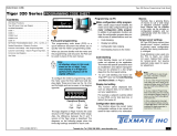
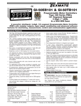
Figure 1 – IGYY Dual Direct Pressure Sensor Input Module Component La yout
Detailed Description
The Tiger 320 Series controller has four input channels capable of processing almost any input
signal type. The dual direct pressure sensor input module IGYY uses only channels 1 and 2.
The input module processes the pressure inputs via b uilt-in pressure sensors capab le of pro-
cessing an absolute or differential pressure input.The pressure signals are then fed to CH1 and
CH2 for further processing. Gain setting resistors are factory installed to optimize the full scale
output for each pressure range. Contact Texmate when ordering to discuss your pressure range
requirements.
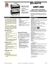
Figure 2 – IGYY Dual Direct Pressure Sensor Input Module Signal Flo w Diagram
SINGLE or
DIFFERENTIAL
PRESSURE
INPUT to CH1
Pressure
S
enso
r
Amplifier
CH1
SINGLE or
DIFFERENTIAL
PRESSURE
INPUT to CH2
Pressure
S
enso
r
Amplifier
CH2
Multiplexer
Tiger A/D
Tiger 320 Series Meter Settings
Channel 1 (CH1) and channel 2 (CH2) configuration settings for the IGYY input module are selected in Codes 2 and 4 respectiv ely of
the Tiger 320 Series meter’s main programming mode. Both CH1 and CH2 m ust be selected as a v oltage input.

IGYY Data Sheet (NZ340) Page 3Texmate, Inc. Tel. (760) 598-9899 • www.texmate.com
PRESSURE
INPUT 1st Digit:X
CH1 CODE 2 [X00]
Select analog sample and output rate as required.
2nd Digit:0 Selects Voltage, Current. (any other selection will not work)
3rd Digit:0 Selects No function. (any other selection will not work)
ANALOG SAMPLE RATE
0 Sample Rate: Typically 10 samples/second (60 Hz)
Control Output Rate: 0.1 seconds
See Example
1 Sample Rate: Typically 10 samples/second (50 Hz).
Control Output Rate: 0.1 seconds
See Example
2 Sample Rate: Typically 10 samples/second (60 Hz)
Counter or 10 millisecs Control Output Rate
See Example
3 Sample Rate: Typically 10 samples/second (50 Hz)
Counter or 10 millisecs Control Output Rate
See Example
Note:
Output Rate ref ers to setpoint and macro outputs ,
and input rates from smart input modules.
Note:
All above sample rates are quoted for single channel
operation. Where more than one channel is available,
sample r ates are divided b y the n umber of activ e
channels. See Example.
FIRST DIGIT
1 Channel = 10 samples/second
2 Channels = 5 samples/second
3 Channels = 3.33 samples/second
4 Channels = 2.5 samples/second
Example: 10 Samples/Second
See the Tiger 320 Series
Programming Code Sheet for a
complete list of main and setpoint
mode programming code settings.
1st Digit:0
CH2 CODE 4 [3X0]
Selects Voltage, Current. (any other selection will not work)
2nd Digit:X Select required setting for CH2.
3rd Digit:0 Selects No function. (any other selection will not work)
FOR VOLTAGE & CURRENT
0 Channel 2 Disabled
1 Direct (no post processing)
2 Square Root of Channel 2
3 Inverse of Channel 2
4 -
5 -
6 -
7-
PRESSURE
INPUT
Calibration
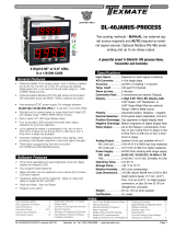
Both channel 1 and channel 2 m ust be individually calibr ated using the tw o-point calibration method. Calibration must be done us ing
a source of pressure equal to the pressure r ange you selected for your meter. For example, if you selected 0-5 psi f or CH1, then you
should be able to apply a pressure of 5 psi from y our source for the meter ’s [SPAn] setting. See Figure 3 and the 2-point calibr ation
procedure on the next page.
1) Enter the meter’s calibration mode and set the display to [111]. This sets you up to calibrate CH1 using the 2-point method.
2) While in the [ZEro] setting mode with no pressure applied, set the displa y to the n umber of counts y ou want to see on the dis play for the
zero setting.
3) Now enter the [SPAn] setting mode and apply the maximum pressure for CH1. Set the display to the number of counts you want to see on
the display for the span setting (full scale).
4) Save the CH1 settings and repeat the procedure f or CH2 by setting the calibration mode to [112].
The high input source is
applied to the meter when
setting the span value.
Programming Tip
All displays shown in this calibration sheet are for a
5-digit, 7-segment display. Using any other display
type in the Tiger 320 Series range will look slightly
different.
Prog.
SP1 SP2 SP4SP3 SP5 SP6
Prog.
SP1 SP2 SP4SP3 SP5 SP6
0
Full
Scale
0
Full
Scale
The low input source is
applied to the meter when
setting the zero value.

Texmate, Inc. Tel. (760) 598-9899 • www.texmate.comPage 4 IGYY Data Sheet (NZ340)
Prog.
SP1 SP2 SP4SP3 SP5 SP6
TEXMATE
Prog.
SP1 SP2 SP4SP3 SP5 SP6
TEXMATE
Prog.
SP1 SP2 SP4SP3 SP5 SP6
TEXMATE
Prog.
SP1 SP2 SP4SP3 SP5 SP6
TEXMATE
Prog.
SP1 SP2 SP4SP3 SP5 SP6
TEXMATE
Prog.
SP1 SP2 SP4SP3 SP5 SP6
TEXMATE
Prog.
SP1 SP2 SP4SP3 SP5 SP6
TEXMATE
Prog.
SP1 SP2 SP4SP3 SP5 SP6
TEXMATE
Prog.
SP1 SP2 SP4SP3 SP5 SP6
TEXMATE
Prog.
SP1 SP2 SP4SP3 SP5 SP6
TEXMATE
Prog.
SP1 SP2 SP4SP3 SP5 SP6
TEXMATE
Prog.
SP1 SP2 SP4SP3 SP5 SP6
TEXMATE
Prog.
SP1 SP2 SP4SP3 SP5 SP6
TEXMATE
Prog.
SP1 SP2 SP4SP3 SP5 SP6
TEXMATE
Prog.
SP1 SP2 SP4SP3 SP5 SP6
TEXMATE
X
Prog.
SP1 SP2 SP4SP3 SP5 SP6
TEXMATE
Prog.
SP1 SP2 SP4SP3 SP5 SP6
TEXMATE
To Step 7
OR
From Step 6
5.2. Apply the LOW
input pressure
OR
OR
Press
1
Press
1
Press
1
Press
1
Press
at same
time
Press
at same
time
Press
at same
time
Press
at same
time
Step 1
Step 2
Step 3
Step 4
Step 5
Step 6
7.2. Apply the HIGH
input pressure
Step 7
Step 8
Step 9
Step 10
Step 11
Enter brightness
mode
Pass brightness mode
and the enter calibration
mode
Select the no function
calibration mode [000]
Save calibration mode
[000] setting and enter
Code 1
Operational Display
Operational Display
Exit code 1 and return
to operational display
Enter calibration
mode [111] for 2-point
calibration of CH1
5.1. Adjust display to
desired reading for
zero input setting
7.1. Adjust display to
desired reading for
span input setting
Set reading for zero
load into meter and
enter span mode
Save zero and span
settings and re-enter
calibration mode
Example
Example
OR
Set calibration mode to [111]:
1st Digit = 1
Selects calibration procedures
2nd Digit = 1
Selects 2-point calibration
3rd Digit = 1
Selects CH1 for calibration
Prog.
SP1 SP2 SP4SP3 SP5 SP6
TEXMATE
Press
1
[111] for CH1
[112] for CH2
0
Full
Scale
0
Full
Scale
ST
STAR
ART HERE
T HERE
Figure 3 – Two-point Calibration Procedure
WARRANTY
Texmate warrants that its products are free from def ects in mater ial and w orkmanship under
normal use and ser vice for a period of one y ear from date of shipment. Texmate’s obligations
under this warranty are limited to replacement or repair, at its option, at its factory, of any of the
products which shall, within the applicable period after shipment, be returned to Texmate’s facil-
ity, tr ansportation charges pre-paid, and which are , after e xamination, disclosed to the satis-
faction of Texmate to be thus def ective. The warranty shall not apply to an y equipment which
shall have been repaired or altered, except by Texmate, or which shall have been subjected to
misuse, negligence , or accident. In no case shall Texmate’s liability e xceed the or iginal pur-
chase price. The aforementioned provisions do not e xtend the original warranty period of an y
product which has been either repaired or replaced b y Texmate.
USER’S RESPONSIBILITY
We are pleased to offer suggestions on the use of our v arious products either by way of print-
ed matter or through direct contact with our sales/application engineering staff. However, since
we ha ve no control o ver the use of our products once the y are shipped, NO WARRANTY
WHETHER OF MERCHANT ABILITY, FITNESS FOR PURPOSE, OR O THERWISE is made
beyond the repair, replacement, or refund of purchase pr ice at the sole discretion of Texmate.
Users shall deter mine the suitability of the product f or the intended application bef ore using,
and the users assume all risk and liability whatsoever in connection therewith, regardless of any
of our suggestions or statements as to application or constr uction. In no event shall Texmate’s
liability, in law or otherwise, be in excess of the purchase pr ice of the product.
Texmate cannot assume responsibility for any circuitry described. No circuit patent or software
licenses are implied. Texmate reserves the right to change circuitry, operating software, speci-
fications, and prices without notice at any time.
Tel: 1-760-598-9899 • USA 1-800-839-6283 • That’s 1-800-TEXMATE
Email: [email protected] • Web: www.texmate.com
1934 Kellogg Ave. • Carlsbad, CA 92008
/