Page is loading ...

1
IMPORTANT:
IMPORTANT:
Go to www.extron.com for the complete
user guide, installation instructions, and
specifications before connecting the
product to the power source.
USB-C HD 101 • Setup Guide
The Extron USB-C HD 101 provides connectivity between USB-C equipped sources and HDMI sink devices. Follow these
instructions to install the USB-C HD 101.
1. Find a location to mount the product. Use the included ZipClip 200
®
mounting bracket and caddy if needed.
2. Connect input and output cables to the product. Use the included LockIt
®
lacing brackets to secure the cables in place to
the product.
3. Apply power to the product.
LED Indicators and Rear Cabling
USB-C HD 101
Front
Rear
USB-C HD 101
USB-C TO INTERFACE
SIGNAL
IN OUT
USB-C HD 101
HDMIUSB-C
60W
50/60 Hz 1.4A MAX
100-240VAC
DD EE F
F
B
B
C
C
A
A
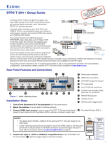
Figure 1. USB-C HD 101 - LED Indicators
USB-C HD 101
Front
Rear
USB-C HD 101
USB-C TO INTERFACE
SIGNAL
IN OUT
USB-C HD 101
HDMIUSB-C
60W
50/60 Hz 1.4A MAX
100-240VAC
DD EE F
F
B
B
C
C
A
A
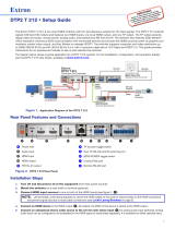
Figure 2. USB-C HD 101 - Rear Panel Ports
A
Power LED — Indicates power to the unit.
B
Power Delivery LED — Indicates power delivery from the USB-C input (
E
) to the USB-C source device.
C
SIGNAL LED — Indicates signal detection from the USB-C input.
D
AC Power Input — Connect the AC Power Cord to the AC Power input port.
E
USB-C input − Connect a USB-C source to the USB-C input.
NOTE: The USB-C port provides up to 60W of power to a connected source device. Some USB-C sources may not be
able to be powered via USB-C. Check the specific source specification or manual for more information. If the source
requires greater than 60W of power, the source may still be able to be powered, may not power, or charge slowly.
F
HDMI output − Connect an HDMI output device to the HDMI output.

2
68-3562-50 Rev. A
07 20
For information on safety guidelines, regulatory compliances, EMI/EMF compatibility, accessibility, and related topics, see the
Extron Safety and Regulatory Compliance Guide on the Extron website.
© 2020 Extron Electronics — All rights reserved. www.extron.com
All trademarks mentioned are the property of their respective owners.
Worldwide Headquarters: Extron USA West, 1025 E. Ball Road, Anaheim, CA 92805, 800.633.9876
Application Diagram
The following is a typical application diagram for the USB-C HD 101.
Figure 3. USB-C HD 101 Application Diagram
LockIt Lacing Bracket
Use the LockIt Lacing Bracket to securely fasten both the USB-C and HDMI cables to the device as follows:
1
Plug the cable into the designated rear panel port.
2
Loosen the connection mounting screw from the panel, enough to allow the LockIt lacing bracket to be placed over
it. The screw does not need to be removed.
3
Place the LockIt lacing bracket on the screw and against the connector.
Then, tighten the screw to secure the bracket.
ATTENTION:
• Do not overtighten the connector mounting screw. The shield it fastens
to is very thin and can easily be stripped.
• Ne serrez pas trop la vis de montage du connecteur. Le blindage
auquel elle est attachée est très fin et peut facilement être dénudé.
4
Loosely place the included tie wrap around the connector and the LockIt lacing
bracket as shown.
5
While holding he connector securely against the lacing bracket, use pliers or
similar tool to tighten the tie wrap. Then, remove any excess length.
3
1
1
1
2
2
2
3
3
3
4
4
4
5
5
5
Figure 4. Lockit Bracket Installation
/