Page is loading ...

User Guide
SW HD 4K Series
HDMI Switchers
HDMI Switchers
68-2884-01 Rev. F
05 20

Safety Instructions
Safety Instructions • English
WARNING: This symbol, , when used on the product, is intended to
alert the user of the presence of uninsulated dangerous voltage within the
product’s enclosure that may present a risk of electric shock.
ATTENTION: This symbol, , when used on the product, is intended
to alert the user of important operating and maintenance (servicing)
instructions in the literature provided with the equipment.
For information on safety guidelines, regulatory compliances, EMI/EMF
compatibility, accessibility, and related topics, see the Extron Safety and
Regulatory Compliance Guide, part number 68-290-01, on the Extron
website, www.extron.com.
Sicherheitsanweisungen • Deutsch
WARNUNG: Dieses Symbol auf dem Produkt soll den Benutzer darauf
aufmerksam machen, dass im Inneren des Gehäuses dieses Produktes
gefährliche Spannungen herrschen, die nicht isoliert sind und die einen
elektrischen Schlag verursachen können.
VORSICHT: Dieses Symbol auf dem Produkt soll dem Benutzer in
der im Lieferumfang enthaltenen Dokumentation besonders wichtige
Hinweise zur Bedienung und Wartung (Instandhaltung) geben.
Weitere Informationen über die Sicherheitsrichtlinien, Produkthandhabung,
EMI/EMF-Kompatibilität, Zugänglichkeit und verwandte Themen finden Sie in
den Extron-Richtlinien für Sicherheit und Handhabung (Artikelnummer
68-290-01) auf der Extron-Website, www.extron.com.
Instrucciones de seguridad • Español
ADVERTENCIA: Este símbolo, , cuando se utiliza en el producto,
avisa al usuario de la presencia de voltaje peligroso sin aislar dentro del
producto, lo que puede representar un riesgo de descarga eléctrica.
ATENCIÓN: Este símbolo, , cuando se utiliza en el producto, avisa
al usuario de la presencia de importantes instrucciones de uso y
mantenimiento recogidas en la documentación proporcionada con el
equipo.
Para obtener información sobre directrices de seguridad, cumplimiento
de normativas, compatibilidad electromagnética, accesibilidad y temas
relacionados, consulte la Guía de cumplimiento de normativas y seguridad
de Extron, referencia 68-290-01, en el sitio Web de Extron, www.extron.com.
Instructions de sécurité • Français
AVERTISSEMENT : Ce pictogramme, , lorsqu’il est utilisé sur le
produit, signale à l’utilisateur la présence à l’intérieur du boîtier du
produit d’une tension électrique dangereuse susceptible de provoquer
un choc électrique.
ATTENTION : Ce pictogramme, , lorsqu’il est utilisé sur le produit,
signale à l’utilisateur des instructions d’utilisation ou de maintenance
importantes qui se trouvent dans la documentation fournie avec le
matériel.
Pour en savoir plus sur les règles de sécurité, la conformité à la
réglementation, la compatibilité EMI/EMF, l’accessibilité, et autres sujets
connexes, lisez les informations de sécurité et de conformité Extron, réf.
68-290-01, sur le site Extron, www.extron.com.
Istruzioni di sicurezza • Italiano
AVVERTENZA: Il simbolo, , se usato sul prodotto, serve ad
avvertire l’utente della presenza di tensione non isolata pericolosa
all’interno del contenitore del prodotto che può costituire un rischio di
scosse elettriche.
ATTENTZIONE: Il simbolo, , se usato sul prodotto, serve ad avvertire
l’utente della presenza di importanti istruzioni di funzionamento e
manutenzione nella documentazione fornita con l’apparecchio.
Per informazioni su parametri di sicurezza, conformità alle normative,
compatibilità EMI/EMF, accessibilità e argomenti simili, fare riferimento
alla Guida alla conformità normativa e di sicurezza di Extron, cod. articolo
68-290-01, sul sito web di Extron, www.extron.com.
I

Copyright
© 2015-2020 Extron Electronics. All rights reserved. www.extron.com
Trademarks
All trademarks mentioned in this guide are the properties of their respective owners.
The following registered trademarks (
®
), registered service marks (
SM
), and trademarks (
TM
) are the property of RGBSystems, Inc. or
ExtronElectronics (see the current list of trademarks on the Terms of Use page at www.extron.com):
Registered Trademarks
(
®
)
Extron, Cable Cubby, ControlScript, CrossPoint, DTP, eBUS, EDID Manager, EDID Minder, Flat Field, FlexOS, Glitch Free. Global
Configurator, GlobalScripter, GlobalViewer, Hideaway, HyperLane, IPIntercom, IPLink, KeyMinder, LinkLicense, LockIt, MediaLink,
MediaPort, NAV, NetPA, PlenumVault, PoleVault, PowerCage, PURE3, Quantum, ShareLink, Show Me, SoundField, SpeedMount,
SpeedSwitch, StudioStation, SystemINTEGRATOR, TeamWork, TouchLink, V-Lock, VideoLounge, VN-Matrix, VoiceLift, WallVault, WindoWall,
XPA, XTP, XTPSystems, and ZipClip
Registered Service Mark
(SM)
: S3 Service Support Solutions
Trademarks
(
™
)
AAP, AFL (Accu-RATEFrameLock), ADSP(Advanced Digital Sync Processing), Auto-Image, AVEdge, CableCover, CDRS(ClassD
Ripple Suppression), Codec Connect, DDSP(Digital Display Sync Processing), DMI (DynamicMotionInterpolation), DriverConfigurator,
DSPConfigurator, DSVP(Digital Sync Validation Processing), eLink, EQIP, Everlast, FastBite, Flex55, FOX, FOXBOX, IP Intercom
HelpDesk, MAAP, MicroDigital, Opti-Torque, PendantConnect, ProDSP, QS-FPC(QuickSwitch Front Panel Controller), RoomAgent,
Scope-Trigger, SIS, SimpleInstructionSet, Skew-Free, SpeedNav, Triple-Action Switching, True4K, True8K, Vector™ 4K, WebShare, XTRA,
and ZipCaddy

FCC Class A Notice
This equipment has been tested and found to comply with the limits for a Class A digital
device, pursuant to part15 of the FCC rules. The ClassA limits provide reasonable
protection against harmful interference when the equipment is operated in a commercial
environment. This equipment generates, uses, and can radiate radio frequency energy and,
if not installed and used in accordance with the instruction manual, may cause harmful
interference to radio communications. Operation of this equipment in a residential area is
likely to cause interference. This interference must be corrected at the expense of the user.
NOTE: For more information on safety guidelines, regulatory compliances, EMI/EMF
compatibility, accessibility, and related topics, see the Extron Safety and Regulatory
Compliance Guide on the Extron website.
VCCI-A Notice
この装置は、クラスA情報技術装置です。 この装置を家庭環境で使用すると、電波妨害を引き
起こすことがあります。 その場合には使用者が適切な対策を講ずるよう要求されることがあります。
VCCI-A

Conventions Used in this Guide
Notifications
The following notifications are used in this guide:
CAUTION: Risk of minor personal injury.
ATTENTION : Risque de blessuremineure.
ATTENTION:
• Risk of property damage.
• Risque de dommages matériels.
NOTE: A note draws attention to important information.
Software Commands
Commands are written in the fonts shown here:
^AR Merge Scene,,0p1 scene 1,1 ^B 51 ^W^C.0
[01] R 0004 00300 00400 00800 00600 [02] 35 [17] [03]
E X!
*
X1&
*
X2)
*
X2#
*
X2!
CE
}
NOTE: For commands and examples of computer or device responses used in this
guide, the character “0” is used for the number zero and “O” is the capital letter
“o.”
Selectable items, such as menu names, menu options, buttons, tabs, and field names are
written in the font shown here:
From the File menu, select New.
Click the OK button.
Specifications Availability
Product specifications are available on the Extron website, www.extron.com.
Extron Glossary of Terms
A glossary of terms is available at http://www.extron.com/technology/glossary.aspx.


SW HD 4K Series • Contents vii
Contents
Introduction............................................................ 1
About this Guide ................................................. 1
About the SW HD 4K Series Switchers ............... 1
Features ............................................................. 1
Application Diagram ........................................... 3
Installation .............................................................. 4
Installation Overview ........................................... 4
Rear Panel Features ........................................... 5
Wiring the Power Connector —
SW2 and SW4 HD 4K Only ............................... 7
Wiring for RS-232 Control and Auto
Switching .......................................................... 9
Connecting to the USB Port ............................. 10
Enabling Auto Switching (Optional) ................... 10
Wiring the Contact Closure Connectors ............ 11
Wiring the Tally Out Port to Indicate the Input
Selection ......................................................... 11
LockIt Lacing Bracket Installation Guide ........... 12
Operation .............................................................. 13
Front Panel Features ......................................... 13
Powering On the Switcher ................................ 15
Selecting an Input ............................................. 15
Resetting .......................................................... 16
Using the Optional IR 102 Remote Control ....... 16
Remote Control Buttons ............................... 16
Locking IR remote access ............................ 17
Locking and Unlocking the Front Panel
(Executive Mode) ............................................. 17
EDID Modes ..................................................... 17
Automatic EDID Mode .................................. 17
User-assigned EDID Mode ............................ 18
Remote Communication and Control ........... 19
Using Simple Instruction Set (SIS)
Commands ..................................................... 19
Host-to-switcher Communications ............... 19
Switcher-initiated Messages ......................... 19
Error Responses ........................................... 20
Using the Command and Response Table .... 20
Symbol Definitions ........................................ 20
Downloading Updated Firmware ....................... 26
Configuration Software ..................................... 28
Downloading and Installing the Product
Configuration Software .................................... 28
Using the Product Configuration Software ........ 31
Starting PCS ................................................. 31
Input/Output Configuration Screen ............... 31
EDID Minder Menu ....................................... 34
General Settings Menu ................................. 35
AV Controls Panel ......................................... 36
Menus .......................................................... 37
Reference Information ...................................... 38
Mounting the SW HD 4K Switchers .................. 38
Tabletop Use ................................................ 38
Rack Mounting ............................................. 38
Furniture Mounting —
SW2 and SW4 HD 4K Only ......................... 39

SW HD 4K Series • Contents viii

SW HD 4K Series • Introduction 1
Introduction
This section gives an overview of the Extron SW HD 4K Series switchers. Topics include:
• About this Guide
• About the SW HD 4K Series Switchers
• Features
• Application Diagram
About this Guide
This guide describes the SW HD 4K Series switchers and discusses how to install,
configure, and operate them.
In this guide, the terms “SW HD 4K Series” and “SW HD 4K” refer to the SW2 HD 4K,
SW4 HD 4K, SW6 HD 4K, and SW8 HD 4K switchers.
About the SW HD 4K Series Switchers
The SW HD 4K Series are two, four, six, and eight input HDMI switchers for 4K video
signals. They switch 4K signals from multiple HDMI source devices to a single display.
The switchers support computer and video resolutions up to 4K and 1080p/60 with Deep
Color, as well as data rates up to 10.2 Gbps, 3D, Lip Sync, and HD lossless audio formats.
All models feature EDID Minder, which maintains continuous EDID communication with
connected devices and ensures that the HDMI sources power up properly and maintain
correct video output. The switchers provide automatic input cable equalization up to
50 feet (15 meters) on Extron HDMI Pro Series cable. The SW HD 4K Switchers can be
controlled via the front panel, RS-232 interface, USB, contact closure, auto-input and
can be integrated into various environments. You can select inputs by pressing the front
panel buttons and IR 102, enabling auto-input switching, attaching a jumper or a contact
closure device to the Contact port, or entering Simple Instruction Set (SIS) commands via
RS-232 or USB.
Features
• Switches HDMI video and embedded multi‑channel digital audio
• Inputs: Two, four, six, or eight female HDMI type‑A connectors
• Output: 1 female HDMI type‑A connector
• Supports computer and video resolutions up to 4K, including 1080p/60 Deep
Color — Resolutions up to 4096x2160/30 with 4:4:4 chroma sampling at 8 bits of
color.
• EDID Minder automatically manages EDID communication between connected
devices — EDID Minder ensures that all sources power up properly and reliably output
content for display.
• Automatic input cable equalization to 50 feet (15 meters) when used with
Extron HDMI Pro Series cable — Actively conditions incoming HDMI signals to
compensate for signal loss when using long HDMI cables, low quality HDMI cables, and
source devices with poor HDMI signal output.

SW HD 4K Series • Introduction 2
• HDCP compliant — Ensures display of content-protected media and interoperability
with other HDCP-compliant devices.
• User‑selectable HDCP authorization — Allows individual inputs to appear HDCP
compliant or non-HDCP compliant to the connected source, which is beneficial if the
source automatically encrypts all content when connected to an HDCPcompliant
device. Protected material is not passed in non-HDCP mode.
• HDCP authentication and signal presence LED indicators
• Automatic color bit depth management — The switcher automatically adjusts color
bit depth based on the display EDID, preventing color compatibility conflicts between
source and display.
• Provides +5 VDC, 250 mA power on the output for external peripheral devices
• Easy setup and commissioning with the Extron Product Configuration Software
— Conveniently configure multiple products using a single software application.
• Multiple control options including front panel, RS‑232, USB, IR, contact closure,
and auto‑input switching
• Contact closure remote control with tally output — Allows for remote selection of
an input channel. +5 VDC is provided to light an LED to indicate the currently selected
input.
• Power supply —
• SW2 and SW4 HDMI: An energy-efficient, external 12 VDC, 1 A universal power
supply with a 2-pole captive screw connector accepts 100 to 240 VAC.
• SW6 and SW8 HDMI: An 50-60 Hz, internal universal power supply with a
standard IEC connector accepts 100 to 240 VAC.
• Includes LockIt HDMI cable lacing brackets
• Rack and Furniture Mounting — The SW HD 4K switchers can be mounted on a
rack shelf or under a desk or podium with an optional mounting kit.

SW HD 4K Series • Introduction 3
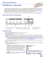
Application Diagram
Figure 1 shows a typical application for an SW4 HD 4K.
SW4 HD 4K
INPUTS
Tx Rx G
GC T GC
G
1
2
3
4
C T TGC
T +V
RS-232 AUTO
CONTACT IN/TALLY OUT
INPUTS
OUTPUT
REMOTE
0.2A MAX
POWER
12V
1
2
3
4
POWER
12V
--A MAX
G
Tx
Rx
RTS
CTS
COM 1
G
Tx Rx
COM 2
V
C
G
VOL
RELAYS
1 2 C
1 2 3 4 G
DIGITAL I/O
PWR OUT = 6W
eBUS
+V+ S
-S
G
LAN
IPCP PRO 250
IR/S
S G
Extron
Extron
Help
System
Off
Display
Room
Control
Off
Mute
Screen
Lighting
December 15, 2013 - 7:58 AM
Audio
Control
Volume
Mute
Tuner
1 2 3
VCR
Laptop
PC
DVD
Doc
Cam
Tuner
On
Channel
Last
Presets
More
Presets
3
2
1
6
54
9
8
7
Enter
0
Laptop
DSS Receiver
4K Media Player
4K Display
Extron
SW4 HD 4K
4K HDMI Switcher
PC
HDMI
HDMI
RS-232
Ethernet
Ethernet
Extron
TLP Pro 720T
7" Tabletop
TouchLink Pro
Touchpanel
Extron
IPCP Pro 250
IP Link Pro Control
Proceesor
TCP/IP
Network
Figure 1. Application Diagram for an SW4 HD 4K Switcher
1

SW HD 4K Series • Installation 44
Installation
This section describes the installation and setup of the SW HD 4K Series switchers. Topics
include:
• Installation Overview
• Rear Panel Features
• Wiring the Power Connector — SW2 and SW4 HD 4K Only
• Wiring for RS‑232 Control and Auto Switching
• Connecting to the USB Port
• Enabling Auto Switching (Optional)
• Wiring the Contact Closure Connectors
• Wiring the Tally Out Port to Indicate the Input Selection
• LockIt Lacing Bracket Installation Guide
Installation Overview
To install and set up the SW HD 4K switcher:
1. Turn off all equipment and disconnect it from the power source.
2. (Optional) Mount the switcher on a rack shelf or furniture (see Mounting the
SW HD 4K Switchers on page38).
3. Connect HDMI input sources to one or more of the SW HD 4K input connectors.
NOTE: LockIt cable lacing brackets are provided to secure the HDMI cables to the
rear panel ports to reduce stress on the HDMI connectors and prevent signal loss
due to loose cable connections (see LockIt Lacing Bracket Installation Guide
on page12).
4. Connect an HDMI output device to the output connector. By default, the EDID of
this device is stored at the HDMI inputs.
5. Connect control devices. Connect your computer to either of the following
SW HD 4K ports to configure and control the switcher via SIS commands:
• RS‑232 port — Pins 1, 2, and 3 of the 3-pole RS-232 connector for serial
RS-232 control (see Wiring for RS‑232 Control and Auto Switching on
page9).
• Config port — USB Mini-B connector for USB control (see Connecting to the
USB Port on page10 for connection procedures)
6. (Optional) Enable auto‑input switching. Use a jumper to connect the two pins
of the 2-pole captive screw connector, next to the 3-pole RS-232 connector (see
Enabling Auto Switching (Optional) on page10).
7. (Optional) Enable input switching by contact closure. Connect an input device to
an SW HD 4K Contact In connector (directly or through a contact closure device) and,
if desired, to a Tally Out connector (see Wiring the Contact Closure Connectors on
page11).

SW HD 4K Series • Installation 5
8. Power on the output display.
9. Connect power to the switcher (see Powering On the Switcher on page15).
10. Configure the EDID Minder (see EDID Modes on page17).
11. Power on the source devices.
Rear Panel Features
SW8 HD 4K
Tx Rx G
GCT GC
G
1
2
3
4
CT TGC
G
68
CT TGC
T
GCT GC
57
T+V
RS-232 AUTO
CONTACT IN/TALLY OUT
INPUTS
OUTPUT
1 2 3 4 5 6 7 8
100-240V x.xA MAX
50/60 Hz
REMOTE
HDMI SWITCHER
SW4 HD 4K
-- A MAX
POWER
12V
12
INPUTS OUTPUT
34
SW6 HD 4K
HDMI SWITCHER
SW6 HD 4K
Tx Rx G
GCT GC
G
1
2
3
4
CT TGC
G
6
CT
T
GCT
5
+V
RS-232 AUTO
CONTACT IN/TALLY OUT
INPUTS
OUTPUT
1 2 3 4 5 6
100-240V x.xA MAX
50/60 Hz
REMOTE
Tx Rx G
GCT GC
G
1
2
3
4
CT TGC
T
+V
RS-232 AUTO
CONTACT IN/TALLY OUT
REMOTE
SW2 HD 4K
-- A MAX
POWER
12V
12
INPUTS OUTPUT
Tx Rx G
GCT
G
1
2
CT
T
+V
RS-232 AUTO
CONTACT IN/TALLY OUT
REMOTE
C
C
C
A
A
A
D
D
D
B
B
B
E
E
E
E
E
E
D
D
D
D
D
D
F
F
F
F
F
F
C
C
C
A
A
A
E
E
E
F
F
F
B
B
B
DDD
FFF
D
D
D
D
D
D
E
E
E
A
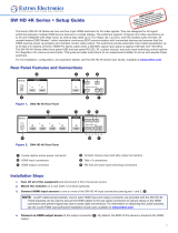
Power connector
B
Input connectors
C
Output connector
D
Contact closure input and Tally output connectors
E
+V connectors
F
RS‑232 and auto switching connectors
Figure 2. SW HD 4K Series Rear Panel
A
Power connector
• SW2 and SW4 HD 4K — Plug the provided external 12 VDC, 1 A power supply
into this 2-pole, 3.5 mm captive screw connector and into an AC power outlet.
ATTENTION:
• Do not connect any external power supplies until you have read the
ATTENTION notices on page 8.
• Ne branchez pas de sources d’alimentation externes avant d’avoir lu les mises
en garde sur la page8.
• SW6 and SW8 HD 4K — Plug the provided AC power cord into this male IEC
connector and into an AC power outlet.
2

SW HD 4K Series • Installation 6
B
Input connectors — Connect HDMI video input sources to these female Type-A HDMI
connectors.
NOTE: LockIt cable lacing brackets are provided with the SW HD 4K units. These
brackets secure the HDMI cables to the rear panel connectors and reduce stress
on the connectors, preventing signal loss due to loose cable connections (see
LockIt Lacing Bracket Installation Guide on page12).
C
Output connector — Connect an HDMI display device to this female Type-A HDMI
connector.
The EDID information is read from the connected output device via this connector and
is written to memory on each input whenever the output device is connected to this
port and powered on.
NOTE: The EDID information is also read and stored whenever power is recycled to
the connected output device or when the output device is replaced.
D
Contact closure input and Tally output ports
• Contact closure input — (Optional) Connect a push-button contact closure
device to a Contact In connector to enable input switching via contact closure (see
Wiring the Contact Closure Connectors on page11 for more information).
• Tally Out port — (Optional) To identify the currently selected input when the
front panel buttons are not visible, connect a device such as an LED to the Tally
Out connector and +V connector. When the input you are using is selected, the
corresponding Tally Out pin (T) shorts to ground, activating the connected indicator
(see Wiring the Tally Out Port to Indicate the Input Selection on page11
for more information).
E
+V connectors — These pins constantly output +5 VDC with 200 mA total (shared
between pins). Use these pins when power is needed for external Tally LEDs, such as
with Extron Show Me cables.
F
RS‑232 (3‑pole) and auto switching (2‑pole) connector — Use this 3-pole, 3.5 mm
captive screw connector for RS-232
communication with the switcher (including
firmware updates) and this 2-pole, 3.5 mm
captive screw connector to enable auto-input
switching.
• To enable RS‑232 control, connect the Tx (transmit), Rx (receive) and G (ground)
pins to the serial port of your computer (see Wiring for RS‑232 Control and Auto
Switching on page9).
• To enable auto‑input switching, short the two pins of this connector together.
In auto-input switch mode, the switcher automatically switches to the highest
numbered active input (see Enabling Auto Switching (Optional) on page10).
Tx Rx G
RS-232 AUTO
SW HD 4K Series Switcher
Rear Panel Remote Port

SW HD 4K Series • Installation 7
Wiring the Power Connector — SW2 and SW4 HD 4K Only
A 12 VDC, 1 A power supply is provided with the SW2 and SW4 HD 4K. Follow the
following instructions to wire the 2-pole captive screw connector to your power supply:
CAUTION: The wires must be kept separate while the power supply is plugged in.
Remove power before wiring.
ATTENTION : Les deux cordons d’alimentation doivent être tenus à l’écart l’un
de l’autre quand l’alimentation est branchée. Couper l’alimentation avant de faire
l’installation électrique.
ATTENTION:
• Do not connect any external power supplies until you have read the ATTENTION
notices on page 8.
• Ne branchez pas de sources d’alimentation externes avant d’avoir lu les mises en
garde sur la page 8.
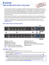
1. Cut the DC output cord to the length needed.
2. Strip the jacket to expose 3/16” (5 mm) of the conductors.
3. Slide the leads into the supplied 2-pole captive screw plug and secure them, using a
small screwdriver.
4. To verify the power cord polarity before connecting the plug, connect the power supply
with no load and check the output with a voltmeter.
5. Use the supplied tie wrap to strap the power cord to the extended tail of the connector.
Captive Screw Connector
Tie Wrap
Heat
Shrink
1/8"
(3 mm)
7/8"
(22 mm)
3/16"
(5 mm) Max.
Figure 3. Wiring the Power Connector
See additional AAttention notes on the next page.
3

SW HD 4K Series • Installation 8
ATTENTION:
• Always use a power supply supplied and or specified by Extron. Use of an
unauthorized power supply voids all regulatory compliance certification and may
cause damage to the supply and the end product.
• Utilisez toujours une source d’alimentation fournie ou recommandée par Extron.
L’utilisation d’une source d’alimentation non autorisée annule toute conformité
réglementaire et peut endommager la source d’alimentation ainsi que le produit
final.
• If not provided with a power supply, this product is intended to be supplied by a
power source marked “Class 2” or “LPS” and rated at 12 VDC and a minimum of
1.0 A.
• Si ce produit ne dispose pas de sa propre source d’alimentation électrique, il doit
être alimenté par une source d’alimentation de classe 2 ou LPS et paramétré à
12 V et 1.0 A minimum.
• The installation must always be in accordance with the applicable provisions of
National Electrical Code ANSI/NFPA 70, article 725 and the Canadian Electrical
Code part 1, section 16. The power supply shall not be permanently fixed to
building structure or similar structure.
• Cette installation doit toujours être en accord avec les mesures qui s’applique
au National Electrical Code ANSI/NFPA70, article725, et au Canadian Electrical
Code, partie1, section16. La source d’alimentation ne devra pas être fixée de
façon permanente à une structure de bâtiment ou à une structure similaire.
• Power supply voltage polarity is critical. Incorrect voltage polarity can damage the
power supply and the unit. The ridges on the side of the cord (see figure3 on the
previous page) identify the power cord negative lead.
• La polarité de la source d’alimentation est primordiale. Une polarité incorrecte
pourrait endommager la source d’alimentation et l’unité. Les stries sur le côté
du cordon permettent de repérer le pôle négatif du cordon d’alimentation (voir
l’illustration figure3 sur la page7).
• To verify the polarity before connection, plug in the power supply with no load and
check the output with a voltmeter.
• Pour vérifier la polarité avant la connexion, brancher l’alimentation hors charge et
mesurer sa sortie avec un voltmètre.
• The length of the exposed (stripped) copper wires is important.
The ideal length is 3/16 inch (5 mm). Longer bare wires can short together.
Shorter wires are not as secure in the connectors and could be pulled out.
• La longueur des câbles exposés est primordiale lorsque l’on entreprend de les
dénuder. La longueur idéale est de 5mm (3/16inches). S’ils sont un peu plus
longs, les câbles exposés pourraient se toucher et provoquer un court circuit. S’ils
sont un peu plus courts, ils pourraient sortir, même s’ils sont attachés par les vis
captives.
• Unless otherwise stated, the AC/DC adapters are not suitable for use in air handling
spaces or in wall cavities.
• Sauf mention contraire, les adaptateurs AC/DC ne sont pas appropriés pour une
utilisation dans les espaces d’aération ou dans les cavités murales.

SW HD 4K Series • Installation 9
Wiring for RS-232 Control and Auto Switching
Use a female 9-pin D to bare wire RS-232 cable or a universal control cable (UC50' or
UC100') to connect your computer or control system to the RS-232 pins of the Remote
connector.
1. Wire the unterminated end of the RS-232 cable to the provided 3-pole captive screw
plug as described below. Connect the transmit, receive, and ground wires of the cable
to the first three pins on the connector, starting at the left:
• Connect the transmit wire to pin 1, which plugs into the Tx (transmit) port.
• Connect the receive wire to pin 2, which plugs into the Rx (receive) port.
• Connect the ground wire to pin 3, which plugs into the G (ground) port.
2. Plug the 3-pole connector into the RS-232 receptacle on the rear panel of the switcher.
3. Connect the other end of the cable to the appropriate computer or control system
connector.
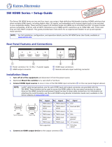
Figure 4 shows how to wire this shared connector for RS-232.
RS-232 Auto
Computer or
Control Syste
m
RS-232 Port
SW HD 4K Series Switcher
Rear Panel Remote Port
NOTE: If you use cable that has a drain
wire, tie the drain wire to ground at both ends.
Tx Rx
G
Ground (G)
Transmit (Tx)
Receive (Rx)
Transmit (Tx)
Receive (Rx)
Figure 4. RS‑232 Connector Pin Assignments
4

SW HD 4K Series • Installation 10
Connecting to the USB Port
The USB mini-B port is located on the SW HD 4K front panel. Use this port to configure the
switcher via SIS commands. Connect a USB A to Mini-B cable between the USB Config
port on the switcher front panel and a USB port on the computer (see figure5).
USB Cable
USB A
USB Mini-B
USB 1
USB
Ports
Computer
SW4 HD 4K Front Panel
SW4 HD 4K
HDMI SWITCHER
1
IR
CONFIG
SIGNAL
INPUTS
INPUTS
OUTPUT
1234
HDCP
2 3 4
AUTO
SWITCH
Figure 5. USB Port Connection
Configure the switcher as desired using SIS commands (see the Remote Communication
and Control on page19, for information on available commands) or PCS (see Using
the Product Configuration Software starting on page31).
Enabling Auto Switching (Optional)
The SW HD 4K can automatically select the active, connected input based on detection
of an active video signal (TMDS clock activity). If two or more inputs are active, the
highest-numbered input port with an active signal is selected (for example, input 4 on
an SW4 HD 4K switcher). When auto-input switching is in effect, the green Auto Switch LED
on the front panel lights and the front panel input buttons are disabled.
To enable auto-input switching:
1. Cut a small piece of wire to use as a jumper.
2. Insert the ends of the wire into the Auto slots (slot 4 and 5) of the provided 2-pole
captive screw plug, connecting pins 4 and 5 together.
3. Use a small screwdriver to tighten the two screws above pin slots 4 and 5 of the plug
so that the jumper wire ends remain securely in place (see figure4 on page9).
4. Insert the plug into the 2-pole Auto captive screw connector on the rear panel (see
figure2 on page5).
The figure at right shows an SW4 HD 4K with a jumper connecting pins 4 and
5 to enable auto-input switching.
Auto-input switching remains in effect as long as the jumper wire connects the
two Auto pins of the 2-pole captive screw Auto port.
5

SW HD 4K Series • Installation 11
Wiring the Contact Closure Connectors
To enable input switching via contact closure, connect a push-button contact closure
device to a Contact In/Tally Out connector (figure2 on page5).
NOTE: The number of the Contact In/Tally Out port must match the number of the
HDMI Input.
1. Wire and plug one of the provided 3-pole connectors into a Contact In/Tally Out
connector representing the desired input number on the SW HD 4K (1 or 2 for SW2
models: 1, 2, 3, or 4 for SW4 models, 1 through 6 for SW6 models, and 1 through 8 for
SW8 models).
• Pin 1 = Contact closure input (C)
• Pin 2 = Contact and Tally Ground (G)
• Pin 3 = Tally output (T)
2. Insert the ground wire of the contact device into the Ground slot of the Contact/Tally
connector (pin 2).
3. Press the button on the contact closure device to switch the connected input to the
output.
4. Insert the ground wire of the contact device into the Ground slot of the Contact/Tally
connector (pin 2).
5. Press the button on the contact closure device to switch the connected input to the
output.
Wiring the Tally Out Port to Indicate the Input Selection
To identify the currently selected input when the front
panel buttons are not visible, connect a device such as an
LED to the Contact In/Tally Out connector (see
figure2,
D
, on page65) and +V connector (
E
).
When the input you are using is selected, the
corresponding Tally Out pin shorts to ground, activating the
connected indicator.
1. Wire and plug one of the provided 3-pole connectors into a Contact In/Tally Out
connector (see the image at right).
• Pin 1 = Contact closure input (C)
• Pin 2 = Contact and Tally Ground (G)
• Pin 3 = Tally output (T)
2. Insert the power wire for the contact indicator device into the
+V connector.
TIP: The Contact and Tally connectors can be used with
Extron Show Me cables. For each cable, connect the red
pigtail to the Contact Closure input pin and the black pigtail
to the Tally Out pin (see the diagram at right).
GCT
1
CONT
ACT IN/TALLY OUT
+V
+V
Connector
Connector
1
CGT
CONT
ACT IN / TALLY OU
T
1
CGT
CONTACT IN / TALLY OUT
Red
Black
Pigtail
Show Me Cable

SW HD 4K Series • Installation 12
LockIt Lacing Bracket Installation Guide
The Extron LockIt lacing bracket makes it possible to simply and universally secure a
standard HDMI cable to most HDMI devices.
NOTE: The HDMI device must have an HDMI connection mounting screw for this
bracket to be used.
To securely fasten an HDMI cable to a device:
1. Plug the HDMI cable into the panel connection
(see
1
in the illustration at right).
2. Loosen the HDMI connection mounting screw
from the panel enough to allow the LockIt lacing
bracket to be placed over it (
2
). The screw
does not have to be removed.
3. Place the LockIt lacing bracket on the screw and
against the HDMI connector, then tighten the
screw to secure the bracket (
3
).
ATTENTION:
• Do not overtighten the connector
mounting screw. The shield it fastens to is
very thin and can easily be stripped.
• Ne serrez pas trop la vis de montage du
connecteur. Le blindage auquel elle est
attachée est très fin et peut facilement
être dénudé.
4. Loosely place the included tie wrap around the
HDMI connector and the LockIt lacing bracket as shown (
4
).
5. While holding the connector securely against the lacing bracket, tighten the tie wrap,
then remove any excess length.
3
3
4
1
2
/