Extron NAV E 511 User manual

Type
User manual

This manual is also suitable for

Extron NAV E 511 is a powerful streaming encoder that allows you to effortlessly distribute and switch AV content over a managed 1G IP network, enabling seamless collaboration and communication. With its versatile connectivity options, including HDMI, analog audio, and USB, you can effortlessly integrate various signal sources and enrich your presentations with engaging multimedia content.

Extron NAV E 511 is a powerful streaming encoder that allows you to effortlessly distribute and switch AV content over a managed 1G IP network, enabling seamless collaboration and communication. With its versatile connectivity options, including HDMI, analog audio, and USB, you can effortlessly integrate various signal sources and enrich your presentations with engaging multimedia content.

1
IMPORTANT:
IMPORTANT:
Go to www.extron.com for the
product specifications.
NAV E 511 • Setup Guide
CLASS 1 LASER PRODUCT, see NAV E 511 User Guide at www.extron.com.
WARNING: The NAV E 511 output continuous invisible light (Class 1 rated), which may be harmful to the eyes; use with caution.
Do not look into the ber optic cable connectors or into the ber
optic cables themselves.
Plug the attached dust caps into the optical transceivers when t
he ber cable is unplugged.
AVERTISSEMENT : Le NAV E 511 émettent une lumière invisible en continu (équipement de classe 1) qui peut être dangereuse pour
les yeux ; à utiliser avec précaution.
Ne pas xer dir
ectement les connecteurs optiques ou les câbles bre optique.
Associez les bouchons anti-poussière à l’ensemble émetteur/récepteur optique lorsque le câble bre optique est débranché.
This guide provides instructions for an experienced installer to install the Extron NAV E 511 streaming encoders and to make all
connections. The Extron NAV encoder and one or more compatible decoders form an AV distribution and switching matrix on a managed
1G IP network.
NOTE: For more information on any subject in this guide, see the NAV E 511 User Guide, available at www.extron.com.
Installation
Step 1 — Mounting
Turn off or disconnect all equipment power sources and rack or furniture mount the encoder as required.
Step 2 — Rear Panel Connections
NAV 1G EXT
HDMI LOOP THRU
POWER
12V
2.0 A MAX
L CONT
CTTx Rx GSG
5V/200 mA
RS-232 IRR
AUDIO
LANUSB 2.0CONTROLINPUT
NAV E 511
RESET
CCCAAA BBB DDDJJJ EEE IIIGGGFFF
HHH
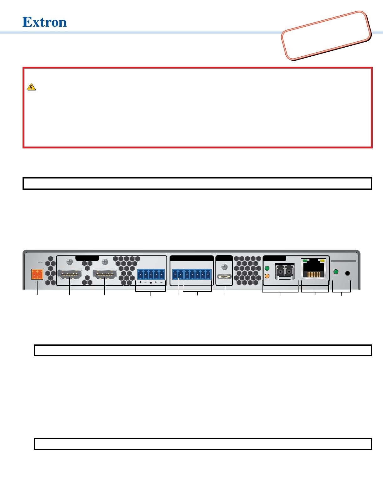
Figure 1. NAV E 511 Rear Panel Features
A
HDMI input port — Connect an HDMI cable between this port and the HDMI output port (or DVI port, with an appropriate adapter) of
the digital video source.
B
HDMI Loop Thru port — Connect a display to this female HDMI connector for local loop-through monitoring of the source signal.
NOTE: See LockIt
®
Lacing Brackets on page 6 to securely fasten the HDMI connectors to the encoder for
A
and
B
.
C
Audio input port — Connect balanced or unbalanced stereo audio input to this 5-pole, 3.5 mm captive screw connector (see Analog
audio input on page 6 to wire the connector).
D
Control Contact Closure port — Connect an Extron Show Me
®
cable to this port to allow the encoder to select itself as the input to
the decoder, using the control system.
E
Control RS-232/IR port — Connect a serial RS-232 signal, a modulated IR signal, or both to this 3.5 mm, 5-pole captive screw
connector for bidirectional RS-232 and unidirectional IR communication with connected remote controlled devices using an Extron
control system (see Control connector on page 6 to wire the connector).
F
USB 2.0 port — Connect a USB Type-C cable from a USB host or a USB device. See LockIt
®
Lacing Brackets on page 6 to securely
fasten the USB connector to the encoder.
NOTE: This connector is limited to supplying 200 mA in USB device mode.
IMPORTANT:
IMPORTANT:
Go to www.extron.com for the complete
user guide, installation instructions, and
specifications before connecting the
product to the power source.
2
G
NAV 1G port (see figure 1 on page 1) — Use a pair of fiber cables to connect to a LAN on which one or more decoders also reside for
streaming and control.
NOTE: Ensure that you use the proper ber cable for your encoder. Typically, singlemode ber has a yellow jacket
and multimode cable has an orange or aqua jacket.
H
Extension port — If desired, connect another networked device to this port. The port acts as a networked 1G switch to the NAV 1G
port (see EXT connector on page 6 to wire the connector).
I
Reset button and LED — This button initiates three modes of reset (see the NAV E 511 User Guide, available at www.extron.com,
for details).
J
Power connector — Plug the included external 12 VDC power supply into this 2-pole connector (see Power connector on page 6 to
wire the connector).
Step 3 — Front Panel Configuration Port Connection
NAV E 511
INPUTS
HDCP
HDMI
CONFIG
USB
STREAM
ACTIVE
HOST
-LNK-
-ACT-
NAVEXT
ANALOG
AUDIO
HDMI AUDIO
NAV LAN IDUSB
EEECCC
AAABBB
DDD
FFF GGG
Figure 2. NAV E 511 Front Panel Features
A
Configuration port — Connect a PC to the encoder via this front panel USB mini-B connector for configuration of the unit. The port
uses IP over USB technology; the IP address is always 203.0.113.22 and CANNOT be changed. The Config port is also discoverable
via Toolbelt (see the NAV E 511 User Guide). The guide and Toolbelt are available for download at www.extron.com).
Indicators
B
Power LED — Indicates power and startup status.
Blinking
— The unit is receiving power and is booting up.
Lit steadily
— The unit is receiving power and is operational.
C
Input LEDs — Indicates status of the signal inputs.
HDMI LED — The encoder is detecting an HDMI input.
HDCP LED — The HDMI signal is HDCP encrypted.
HDMI Audio LED — The embedded HDMI audio input is selected.
Analog Audio LED — The analog audio input is selected.
D
NAV LEDs — Indicate the output status of the A/V and USB streams, as follows:
Stream
Lit steadily – The encoder is actively streaming a NAV output consisting of video, audio, or both.
Blinking
– The encoder is actively streaming a NAV output, but network errors are present.
Unlit - The encoder is not actively streaming a NAV output consisting of video, audio, or both.
USB
Lit steadily – The encoder is actively sending and receiving a NAV USB stream.
Blinking
– The encoder is unable to establish a NAV USB stream.
Unlit
— The encoder is not actively sending and receiving a NAV USB stream.
3
NAV E 511 • Setup Guide (Continued)
E
USB LEDS (see figure 2 on page 2 — Indicates the status of the USB stream, as follows:
Host
Lit steadily
– The encoder is in USB host mode, the default condition.
Unlit
– The encoder is in USB device mode.
Active
Lit steadily – A host or USB device is connected to the rear panel USB port.
Unlit
– No host or USB device is connected to the rear panel USB port.
Blinking
– A USB device or hub is connected to the encoder and is drawing more power than the USB port can supply.
F
LAN LEDs — Indicates status of the network connection.
NA
V LED
Link LED
— Lit steadily indicates that a network link is established at 1G.
Act LED
— Blinking indicates network traffic. The blink rate corresponds to activity.
Ext LED
Link LED — Lit steadily indicates that a network link is established at 1G. Blinking indicates a link speed less than 1Gbps.
Act LED
— Blinking indicates network traffic. The blink rate corresponds to activity.
G
ID button and LED — The recessed ID button identifies the encoder to the NAVigator and decoder when pressed. The LED blinks
when the encoder is in pairing mode (see Pairing devices via front panel on page 5 for details).
Operation
Power
When power is applied, the encoder runs a series of self-tests that blink the front panel Power LED and all other indicators. The encoder
then boots the NAV operating system. It can take approximately 45 seconds for self-test and system startup to complete. When the
process is complete, the Power LED lights steadily.
NOTE: The encoder is NOT operational until the boot process is complete (the Power LED is lit steadily).
System Operation
The encoder can be congured and controlled using embedded web pages or Extron Toolbelt (see the NAV E 511 User Guide available at
www.extron.com and the Toolbelt Help le).
NOTE: The “Connection via web pages,” Connection settings, and Pairing devices via front panel procedures (see page 5) may
NOT be necessary if your system includes a NAVigator System Manager
.
4
Connection via web pages
Connection to the encoder and its embedded web pages can be made via either the front panel Conguration (USB) port (using IP over
USB technology) (see figure 2,
A on page 2) or the rear panel NAV 1G port (see figure 1, F on page 1).
Access the encoder using HTML pages as follows:
1. Start a web browser.
NOTES:
Suggested br
owsers to fully support the NAV system are: Google Chrome, Mozilla Firefox, and Microsoft
®
Edge.
The network must be pr
operly congured for multicasting (IGMP). Failure to do so may result in degraded performance.
2. Enter the IP address of the encoder in the browser Address field.
NOTES:
Default settings:
Port DHCP IP address Subnet mask
Config (USB)* 203.0.113.22
NAV 1G (Fiber)
On
* For the Config port, the address for IP over USB
CANNOT be changed.
If the unit does not receive a DHCP address,
a self-assigned Link Local Address, is assigned in
the range 169.254.X.X.
If you use IP over USB, Extron recommends waiting a minute after plugging in the cable for your PC to identify the USB
connection as a valid Ethernet port.
3. Press the keyboard <Enter> key. The browser
displays a privacy error message (see figure 3 at right
for an example in the Chrome browser).
4. Click Advanced (see figure 3, 1). The button changes
to Hide Advanced and explanatory text and a link
appear below the button.
5. Click Proceed to <IP address> (unsafe) (2). The
browser opens to the Login dialog box (see figure 4).
11111111111111
22222222222222
33
3333
33333333
Figure 4. Login Dialog Box
6. Enter the Username (see figure 4, 1) and Password (2) and click Sign In (3). The browser opens to the embedded web pages
(see figure 5).
NOTES:
The default Username is admin.
The factory congured passwords for all accounts on this device have been set to the device serial number. If the password
is reset, the encoder reverts to the default password, which is extron.
Usernames and passwords are case sensitive.
1111111111
1111
1111
2222222222
2222
2222
Figure 3. Privacy Error Message (in Chrome Browser)
5
NAV E 511 • Setup Guide (Continued)
1111111111
1111
1111
2222222222
2222
2222
Figure 5. HTML Page
NOTE: Detailed descriptions of communication, conguration, and monitoring are provided in the NAV E 511 User Guide,
available at www.extron.com.
Connection settings
View and change connection settings as follows:
1. On the home page, click Settings (see figure 5, 1) and then Network
Connection (
2). The Network Connection pane opens (see figure 6),
showing protected views of the network connection settings.
NOTE: Editing of connection settings is disabled when the
device is assigned to an Extron NAVigator System Manager.
2. To change the settings, click Edit (see figure 6, 1). The Edit button
changes to Save.
3. Click in the desired field (2) and edit it as necessary.
4. Repeat step 3 as necessary for other values.
5. Click Save.
Pairing devices via front panel
Pair devices as follows:
AV E 511
ID
A
A
A
A
1. Use a Tweeker or other small screwdriver to press
and hold the encoder front panel ID button for
approximately 3 seconds, until the ID LED blinks. The
encoder enters pairing mode, which allows decoders
to receive the AV and USB streams from encoders.
2. One at a time, use a Tweeker or other small screwdriver to press and hold
the decoder front panel ID button for approximately 3 seconds, until the
ID LED blinks three times. The decoder is now paired to the encoder.
3. Repeat step 2 for each decoder.
1111111111
1111
1111
2222222222
2222
2222
Figure 6. Network Connection Pane
6
68-3605-50 Rev. A
01 21
For information on safety guidelines, regulatory compliances, EMI/EMF compatibility, accessibility, and related topics, see the
Extron Safety and Regulatory Compliance Guide on the Extron website.
© 2021 Extron — All rights reserved. www.extron.com
All trademarks mentioned are the property of their respective owners.
Worldwide Headquarters: Extron USA West, 1025 E. Ball Road, Anaheim, CA 92805, 800.633.9876
4. Use a Tweeker or other small screwdriver to press and release the encoder front panel ID button. The encoder exits pairing mode.
5. Repeat steps 1 through 4 to pair decoders to other encoders.
After all devices are connected, powered on, and paired, the system is fully operational.
Operation in a System with a NAVigator
The Extron NAVigator is a system manager that easily congures and controls the NAV System. The NAVigator supports 16 endpoints by
default, but a LinkLicense can upgrade its capabilities to support up to 240 endpoints.
See the NAVigator User Guide, available at www.extron.com for details.
Connection Details
LockIt
®
Lacing Brackets
1. Plug the HDMI or USB cable into the panel connection (see 1, at right for an HDMI example).
3
333
111
555
444
222
2. Loosen the connection mounting screw from the panel enough to allow the LockIt lacing bracket to
be placed over it (
2
). The screw does not have to be removed.
3. Place the LockIt lacing bracket on the screw and against the connector (
3
), then tighten the screw
to secure the bracket.
ATTENTION:
Do not overtighten the connector mounting screw. The shield it fastens to is very thin
and can easily be stripped.
Ne serr
ez pas trop la vis de montage du connecteur. Le blindage auquel elle est
attachée est très n et peut facilement être dénudé.
4. Loosely place the included tie wrap around the connector and the LockIt lacing bracket as shown (
4
).
5. While holding the connector securely against the lacing bracket, use pliers to tighten the tie wrap, then remove any excess length (
5
).
Analog audio input EXT connector
Unbalanced Stereo Input
Balanced Stereo Input
Do not tin the wires!
Tip
Ring
Tip
Ring
LR
Sleeves
Tip
Sleeve
Sleeve
Tip
LR
5
Pin
1
2
3
6
7
8
4
Wire color
White-green
Green
White-orange
White-blue
Orange
White-brown
Brown
Blue
TIA/EIA T568B
TP Wires
12345678
Pins:
Control connector Power connector
TxRx
RxTx Gnd
IR Device
Tally out
Contact
Show Me Cable
RS-232
Device
RS-232
Tx Rx GSG
IRCONT
CT
CONTROL
Power Supply
Output Cord
Ridges
Smooth
Captive
Screw
Connector
3"
16 (5 mm) MAX
SECTION A–A
AA
  • Page 1 1
  • Page 2 2
  • Page 3 3
  • Page 4 4
  • Page 5 5
  • Page 6 6

Extron NAV E 511 User manual

Type
User manual
This manual is also suitable for

Extron NAV E 511 is a powerful streaming encoder that allows you to effortlessly distribute and switch AV content over a managed 1G IP network, enabling seamless collaboration and communication. With its versatile connectivity options, including HDMI, analog audio, and USB, you can effortlessly integrate various signal sources and enrich your presentations with engaging multimedia content.

Ask a question and I''ll find the answer in the document

Finding information in a document is now easier with AI