Page is loading ...

CELLCOMEX HOW-TO GUIDE:
DSC PASSTHRU

TABLE OF CONTENTS
DSC Passthru Overview .......................................................................................... 1
Procedure ............................................................................................................................................................. 1
Required Materials ............................................................................................................................................ 1
Step 1: Mount the Communicator ......................................................................... 2
Step 2: Wire the Communicator ........................................................................... 2
Step 3: Configure DSC Settings ........................................................................... 4
Remotely (Dealer Admin) .............................................................................................................................. 4
Step 4: Remote DLS Programming ...................................................................... 5
Retrieve Codes for DSC Connection ......................................................................................................... 5
Configure Remote Link ................................................................................................................................... 5
Configure DLS .................................................................................................................................................... 6
Connect to the DSC Panel and Complete Remote Programming ................................................. 7
Reference ................................................................................................................. 8
Virtual Keypad .................................................................................................................................................... 8
DSC Panel Compatibility ................................................................................................................................ 8

CELLCOMEX SERIES HOW-TO GUIDE: DSC PASSTHRU | DIGITAL MONITORING PRODUCTS 1
DSC PASSTHRU OVERVIEW
CellComEX Universal Communicators enable you to take over and manage DSC panels with connection to
the DSC Bus. This feature is called DSC Passthru.
This guide is designed to walk you through DSC passthru installation and setup. For more complete
information on CellComEX setup, refer to the CellComEX Installation and Programming Guide (LT-2663).
Procedure
The installation must follow this procedure:
Step 1: Mount the communicator.
Step 2: Wire the communicator.
Step 3: Configure DSC settings remotely.
Step 4: Changing programming.
Required Materials
The following software and hardware components are required to perform system takeovers:
• Compatible DSC PowerSeries Panels (refer to “DSC Panel Compatibility”)
• Dealer Admin
• 18-22 AWG unshielded wire (RYGB)
• Remote Link minimum Version 2.21
• (Optional) Model 330-DSC programming harness and DLS panel programming software
+DC- GTR
O
+ Z -
PROG
R
B
C
D
A
G
E
F
CellComEX
DC Power
Zone 1
Tip
Output
Ground
Ring
A
B
C
D
E
F
G
Cellular Antenna
SMA Connector
Cell Modem
Programming Connection
Terminal Block
Reset Pads
Status LEDs
STAT US
+DC- GTR
O
+ Z -
RESET
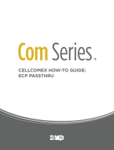
Figure 1: CellComEX Components

CELLCOMEX SERIES HOW-TO GUIDE: DSC PASSTHRU | DIGITAL MONITORING PRODUCTS 2
STEP 2: WIRE THE COMMUNICATOR
Caution: Remove all AC and battery power from the panel before wiring.
1. Attach the antenna to the SMA connector. Refer to Figure 1.
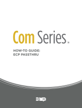
2. The communicator can be connected to the DSC Bus of a compatible DSC panel. See Table 1 and
Figure 2 for the necessary wiring connections.
3. Connect the DSC panel to a 12 VDC power source. Connect DSC backup batteries as needed.
STEP 1: MOUNT THE COMMUNICATOR
The module comes in a high-impact plastic housing that you can mount directly to a wall, backboard, or
other flat surface.
For easy installation, the back and ends of the CellComEX housing have wire entrances. The back also
contains multiple mounting holes that allow you to mount the module on a single-gang switch box.
Remove the PCB from the plastic housing by loosening the clips on one side and gently lifting it out of the
housing base.
Insert the included screws in the desired mounting hole locations and tighten them to secure the housing to
the surface.
Reinstall the PCB in the housing base.

CELLCOMEX SERIES HOW-TO GUIDE: DSC PASSTHRU | DIGITAL MONITORING PRODUCTS 3
DSC PC1864
AC AC +AUX- +BELL- RED BLK YEL GRN 1 PGM 2 3 PGM 4 Z1 COM Z2 Z3 Z4 Z5 Z6 Z7 Z8 EGND RING TIP R-1 T-1COM COM COM
AC +AUX- +BELL- RED BLK YEL GRN 1 PGM 2 3 PGM 4 Z1 COM Z2 Z3 Z4 Z5 Z6 Z7 Z8 EGND
A
RING
B
TIP
C
R-1
D
T-1
COM COM COM
1k Ω
EOL 5.6k Ω EOL
To AC
Power
From DC +
From DC -
From Z +
From Z -
From T
To RED
To BLK
To YEL
To TIP
To RING
To GRN
From R
RED
BLACK
BLACK
BLACK
YELLOW
GREEN
GREEN
RED
Remote
Programming
Connection
(Model 330-DSC)
PC LINK
+DC- GTR
O
+ Z -
PROG
1
CON 4
YELLOW
GREEN
YELLOW
GREEN
TAB
UP
BR
Figure 2: DSC Wiring
Communicator to DSC Wiring
Com DSC Bus Typical Color
DC+ RED Red
DC- BLK Black
Z+ YEL Yellow
Z- GRN Green
T TIP Green
R RING Red
N/A Bell+ to Bell- (1k Ω EOL) N /A
N/A Zones 1 - 8 (5.6k Ω EOL) N /A
PROG PC Link (COM) Tab Up Green, Yellow
Table 1: Wire Connections

CELLCOMEX SERIES HOW-TO GUIDE: DSC PASSTHRU | DIGITAL MONITORING PRODUCTS 4
STEP 3: CONFIGURE DSC SETTINGS
For the communicator to properly process data from the VISTA panel, keypad input must be set to ECP. You
can perform this programming remotely with Dealer Admin.
Why is this important? Dealer Admin configures the CellComEX to receive DSC data.
Remotely (Dealer Admin)
1. Go to Customers.
2. Find and select the system name.
3. Go to Programming > System Options.
4. In Keypad Input, select DSC.
5. Press Begin DSC Setup.
6. Enter the host panel’s installer code in Installer Code.
7. Press Begin.
8. After setup is complete, Dealer Admin automatically retrieves zones from the host panel. If you need to
retrieve zones again later, open System Options and select Get Zones.
9. At USER NUMBER, enter 40.
10. At CODE NO, enter the code from the DSC panel’s user 40.
11. At USER NAME, enter MASTER.
12. At MASTER? select the checkbox.
13. Press Send.

CELLCOMEX SERIES HOW-TO GUIDE: DSC PASSTHRU | DIGITAL MONITORING PRODUCTS 5
STEP 4: CHANGING PROGRAMMING
Option 1: Programming with Host Keypad
If you have access to the host panel, you can make zone programming changes in the panel locally using
a host keypad. To retrieve new zone programming, select Get Zones in the System Options tab in Dealer
Admin.
Option 2: Programming using DLS and Remote Link
Starting with Remote Link™ Version 2.21, you can connect a customer’s DSC panel with CellComEX
communicators using DLS software and Remote Link.
Why is this important? Remote Link is necessary if programming using DLS. It provides a link between
the CellComEX and the host panel. Without doing this, no new programming (zones, devices, etc.) can be
sent to or retrieved from the host panel.
Retrieve Codes for DSC Connection
DSC panels allow a 6-hour interval for remote programming connections after the panel is initially powered
up. After that interval expires, technicians can re-enable DLS connection for another 6 hours by disarming
the panel and entering the following code combination: *6 + [master code] + 5.
Before attempting to program a DSC panel remotely, you will need to find and record the DSC panel’s 6-digit
Downloading Access Code and the Panel Identification Code (Device ID). You can retrieve this information at
the panel’s keypad from Section [403] and Section [404], respectively.
Configure Remote Link
1. Right-click Remote Link and select Run as administrator. If you already have Remote Link open and
recently used DSC passthru, close and reopen Remote Link.
2. If necessary, create the communicator account.
3. In Panel Information, double-click the communicator account to open it.
4. Go to Panel > Connect. Ensure the account number is correct, then press Connect.
5. Go to Program > System Options.
6. Ensure DSC is selected.
6
7
9

CELLCOMEX SERIES HOW-TO GUIDE: DSC PASSTHRU | DIGITAL MONITORING PRODUCTS 6
7. Press OK.
8. Go to Panel > Disconnect. Ensure the account number is correct, then press Disconnect. The panel must
be disconnected in Remote Link before connecting in DLS.
9. Ensure the bottom right corner of the main Remote Link window displays DSC ON.
10. Minimize the Remote Link window. Remote Link must remain open during remote DSC programming.
Configure DLS
1. Open DLS5 and select New Account.
2. Enter an account name.
3. In Panel Type, select the model of the DSC panel.
4. In Connection Type, select IP (TLink).
5. Leave all other settings at their defaults and press Create.
2
3
4
5

CELLCOMEX SERIES HOW-TO GUIDE: DSC PASSTHRU | DIGITAL MONITORING PRODUCTS 7
Connect to the DSC Panel and Complete Remote Programming
1. Back in the DLS5 main window, open the account you just created by double-clicking it.
2. Press Connect.
3. In Access Code, enter the 6-digit Downloading Access Code.
4. In Device ID, enter the Panel Identification Code.
5. Clear the following checkboxes: Automatically Hangup when Finished and Override default connection
type with PC-Link.
6. Press OK.
7. In the main DLS5 window, the Communication toolbar displays the connection status. Efficiency should
ideally be green, indicating good connection. State should display Online Idle, indicating that the panel
is connected and idle. To troubleshoot connectivity issues, select Connection Log. In the connection
log, errors are red.
8. Edit programming as needed, then press Upload Programming.
Retrieving Zones in Dealer Admin
After programming in DLS is completed, navigate to the System Options tab in Dealer Admin and press Get
Zones. This ensures any new programming can be viewed in Virtual Keypad and Dealer Admin.
34
5
6

18205
Designed, engineered, and
manufactured in Springfield, MO
using U.S. and global components.
LT-2690 22355
INTRUSION • FIRE • ACCESS • NETWORKS
2500 North Partnership Boulevard
Springfield, Missouri 65803-8877
800.641.4282 | DMP.com
© 2022
REFERENCE
Virtual Keypad
Virtual Keypad enables users to manage their systems remotely, including arming, disarming, viewing zone
status, bypassing zones, viewing history, managing users, and more.
To use Virtual Keypad for remote management, the configuration must meet the following conditions:
• DSC Panels must be programmed as Stay/Away for remote arming and disarming (No Partitions).
• User code 40 must match in both the communicator and DSC panels and must also be used when
logging into Virtual Keypad to remotely manage DSC panels.
DSC Panel Compatibility
Panel Type DSC Remote
User Management
Remote
Arming/Disarming
Remote
Zone Status
Compatible with
DLS5
PC1616 Yes Yes Ye s Yes Firmware version
4.1 and higher
PC1832 Yes Yes Yes Yes Firmware version
4.1 and higher
PC1864 Yes Yes Yes Yes Firmware version
4.1 and higher
PowerSeries
Neo panels Untested Untested Untested Untested Firmware version
1.0 and higher
/