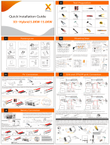
Communication Connection(BMS/Meter/CT/COM/DRM)
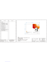
Monitoring Operation
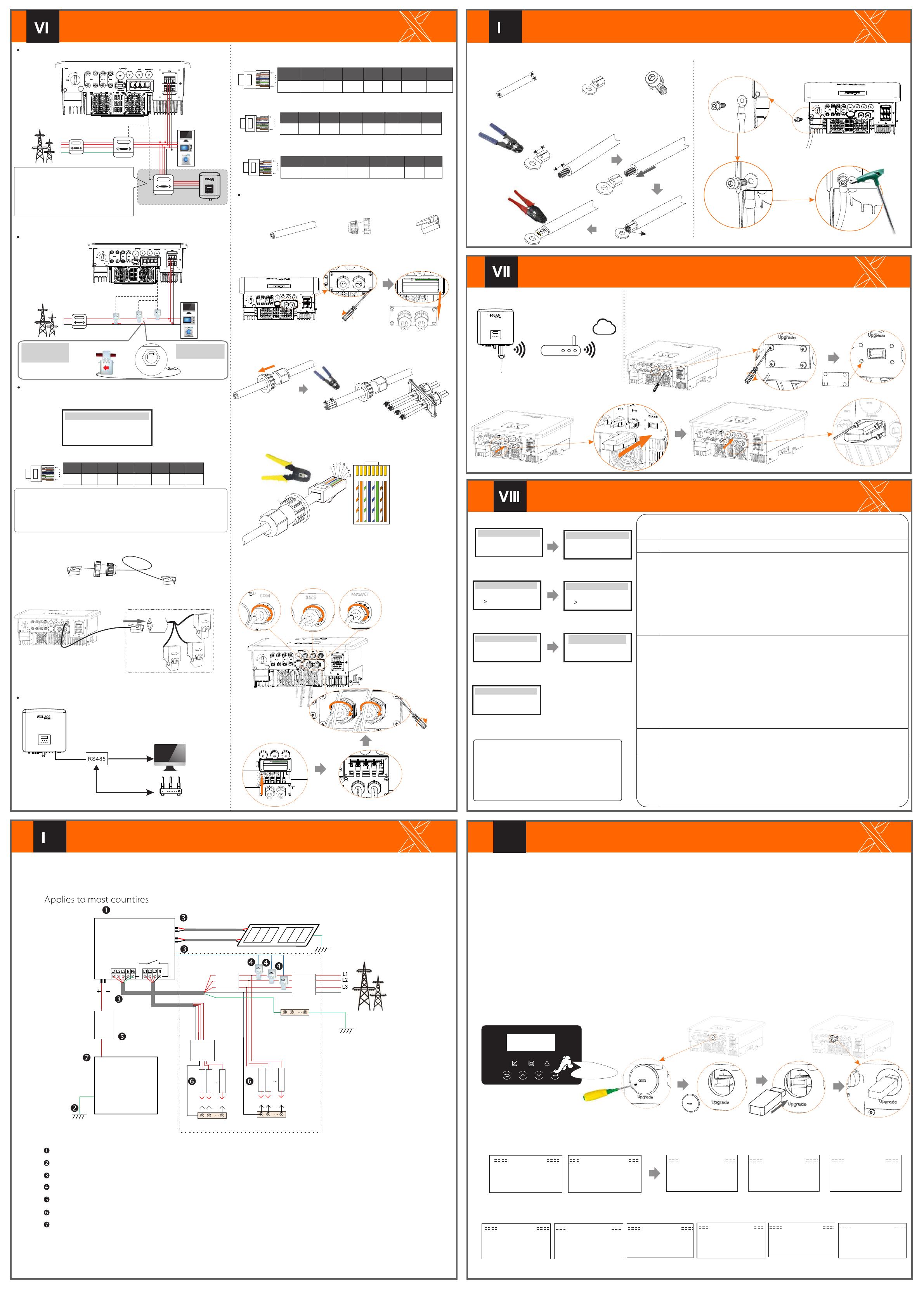
Firmware Upgrading
614.00499.01
x
Electric meter connection diagram
CT connection diagram
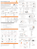
LCD settings
To select CT, you need to enter Use setting, then enter CT/Meter
Setting.
>Select
CT
CT/Meter Setting
Step 1. Prepare a communication cable, and then find the communication
adapter in the accessory bag.
Step 3. Insert the communication cable through the communication
adapter, and peel off the outer insulation layer of15mm.
15.00mm
Diagonal pliers
1 2 3456 7 8
Communication Connection Steps
COM Communication
Step 5: Insert the communication line (CAN/DRM/SHUT) into the
corresponding port, lock the cover plate, and tighten the fastening
head .Finally, the corresponding COM, METER, CT and BMS can be found
to insert the corresponding ports of the inverter communication cable.
Start Inverter
x
ØDONGLE connection diagram Wireless monitoring accessories connection steps:
Ø
Step 1. Of the DONGLE port of the inverter needs to unscrew the screw and take off the
cover.
Cover
Dongle
Step 2. Plug the Pocket WiFi Plus into the DONGLE port, use step 1 to remove the four screws and tighten it.
Start Guide
English
Deutsch
Italian
Language
2.Set language
2017 ->06 <-06
10:19
Date time
1.Set date time
Country
VDE0126
Safety
3.Set the safety standard
CT
Meter
CT/Meter Setting
4.CT/Meter Setting
Export control
Use Value:
10000W
Export Control
This function allows the inverter able to control
energy exported to the grid.
There are user value and factory value. The factory
value is default which can not be charged by user. The
user value set by installer must be less than the factory
value.
5 .Set export control*
>disable
enable
X3-Matebox Setting
7.X3-Matebox Setting
-In order to upgrade the firmware smoothly, if the DSP and ARM firmware needs to be upgraded, please note that ARM firmware must be upgraded
first, then DSP firmware!
-Make sure that this directory is completely consistent with the above table, do not modify the firmware file name,Otherwise, the inverter may not work!
-For X3-Hybrid G4, ensure that the PV input voltage is greater than180V (upgrade on sunny days). please ensure that the battery SOC is greater than 20%
or the battery input voltage is greater than 180V. Otherwise, it may cause serious failure during the upgrade process!
-If the ARM firmware upgrade fails or stops, please do not unplug the U disk and power off the inverter and restart it. Then repeat the upgrade steps.
Upgrade preparation
1) Please check the inverter version and prepare a U disk (USB 2.0) and personal computer before upgrading.
2) Please contact our service support through service@solaxpower. com to obtain the firmware, and store the firmware in the U disk according to the
following path.
Ø
Update:
For ARM le:“update \ARM\618.00406.00_Hybrid_X3G4_ARM_V1.01.0710.usb”;
For DSP le:“update\DSP\618.00405.00_Hybrid_X3G4_DSP_V1.01.0710.usb”;
Upgrade steps
Step 1. Please save the "Upate" firmware in your U disk first, and press the "Enter" button on the machine screen for 5 seconds to enter the shutdown
mode. Then unscrew the waterproof cover, insert the U disk into the "upgrade" port at the bottom of the inverter.
Ø
Step 2. Locate the "update" port of the inverter, use a flat-blade screwdriver or coin with the same width to remove the waterproof cover, and insert
the U disk.
Waterproof cover
U Disk
Step 3. LCD operation, enter the upgrade interface "update", as shown below(a): Please press the up and down keys to select ARM, then press the
bottom of the page to select "OK", press the enter key to enter the software version interface;
Update ARM
Cancel
>OK
>ARM
DSP
Update (ARM )
Update ( ARM)
>618.00406.00_Hybrid_
X3G4_ARM_V1.01
0710.usb
(c)
>ARM
DSP
(e)
Upgrading---------25%
(d)
(a) (b)
Step 4. Please confirm the new firmware version again and select the firmware to upgrade. The upgrade takes about 20 seconds. (d) When it is
completed, the LCD screen returns to the "Update" page.
(k)
Update(DSP)
Upgrade Successful
Update(DSP)
connect---------
Update DSP File
>618.00405.00_Hybrid_
X3G4_DSP_V1.01_07
10.hex
(g)
Update Selection
ARM
>DSP
( f ) (h)
Update(DSP)
Upgrading---------25%
Update(DSP)
(i) (j)
DSP Erasing---------
6 .Set work mode*
>Mode Select
self use
Work Mode
5*.Export Control
Update ARM File Update( ARM)
DRM4/8 +3.3V DRM0 GND GND
The DRM pin is defined as follows:
DRM1/5 DRM2/6 DRM3/7
1 2 3 4 5 6 7 8
1
8
Ø
Meter/ CT PIN is defined as follows:
Ø
COM PIN Definition
Ø
Drycontact_A(in)
GND
485A 485B
+13V
123 4 56 7 8
1
8
BMS_CANL X
12 3 456 7 8
1
8
BMS_485A BMS_485BBMS_CANH
The BMS pin is defined as follows:
XXX
Ø
Phillips screwdriver
Torque: 1.0±0.2N·m
Flat-blade screwdriver or coin
(Port size: 12*2mm;
Torque: 1.5±0.2N·M)
Long press for 5
seconds
Grounding Connection(manodatory)
x
Step 2. Strip the grounding cable insulation(length”L2), insert the
stripped cable into the ring terminal, and then clamp it.
L1
12AWG
C
L2=L1+3mm
Diagonal pliers
Leaking cable
Crimping Tool
Step 1. Prepare a one-core cable (12AWG), and then find the ground
terminal in the accessories.
Hexagon keys
Torque: 1.5±0.2N·m
Step 4. Find the ground connection port on the inverter, and lscrew the
ground wire on the inverter with an M5 Allen key.
Start inverter
Ø
Communication cable Communication adapter
Multifunction terminal
crimping tool (RJ45)
1) White with orange stripes
2) Orange
3) White with green stripes
4) Blue
5) White with blue stripes
6) Green
7) White with brown stripes
8) Brown
After the inverter is checked, the inverter will take the following steps:
Turn on the Load switch and Off-grid switch
Turn on thebattery switch.
Make sure the battery is well connected.
Make sure the CT are connected.
Confirm that all DC lines and AC lines are connected.
Make sure that the inverter is fixed on the wall.
Long press Enter for 5 seconds to exit the shutdown mode. Mode is the mode when it is
turned off for the first time; factory default: off mode)
Ensure that all ground wires are grounded.
One-core cable (12 AWG) OT terminal Hexagon socket screws
Date Read
Date Read
Date Write Smart control device
(developing)
Dongle
ngle
Grid
Household Meter
Three-phase meter Load
L1
N
Other power generation
equipment
Meter1
Meter2
If the user has other power generation
equipment (such as inverter) at home and
wants to monitor both, X3-Hybrid G4 inverter
provides Meter2 communication function to
monitor the power generation equipment.
For more information, please contact SOLAX.
Off-grid
L2
L3
L Line
CT
Public Grid
electricity
Meter/CT port is at the
bottom of the inverter.
Note:The arrow on the
CT must point at the
public grid.
Meter/CT
Grid
Household Meter
Loads
L1
N
CT 3
L2
L3
CT 2CT 1
1
8
12 3 4 5 6 7 8
485A 485B CT2-2 CT1-2CT1-1 CT3-2
CT3-1
CT2-1
Note!
Only one of the Meter and CT connections can be selected. Meter
cable goes to pin terminal 4 and 5; CT1 cable to PIN Terminal 4 and
5; CT2 cable to PIN Terminal 1 and 8; C T3 cable is connected to
terminals 3 and 6.
Grid
Off-g rid
CAN CA N LCD DRM
Step 2. Remove the cover plate on the inverter. Will make the
communication line.
15.00mm
Step 4. Insert the prepared communication cables into the RJ45 terminals
in sequence , and then use network cable crimping pliers to
press them tightly.
CAN CAN DRM SHU T
CAN CAN DRM SHUT
CAN C AN DRM SH UT
Gri d
Off- grid
CAN C AN LCD DR M
Gri d
Off- grid
CAN C AN LCD DR M
N
BAT
Battery
N-BAR for loads
N-BAR for off-grid loads
off-grid loads Loads
X3-Hybrid G4
PV 1
PV 2
E-BAR
RCD
Breaker
Grid
Breaker
Grid Off-grid
Main Breaker/RCD
Breaker
Breaker
CT
Distrbution Box
Dongle
Off-grid
Torque screwdriver
( Torque: 1.2±0.1N·m)
CAN CAN DRM SHUT
There are 4 work modes for choice. Self use/ Back Up Mode/ Feed in Priority/ Force Time Use
All these work modes is available for on-grid condition only:
Name Description
Off-grid
Self Use
Backup
Feed-in
mode
priority
6*.Set work mode
The self-use mode is suitable for areas with low feed-in subsidies and high electricity prices.
① When the power of PV is sufficient
Active Charging or Discharge time period: PV will power the loads rstly, and surplus power will charge to the battery .
If the battery is fully charged, then sell the surplus power to the grid;( The inverter will limit the output if Feed-in limit
or zero feed-in is needed ) (PV>Load ,PV →Load→Battery → Grid)
② When the power of PV is insufficient
Active Charging time period: PV will power the loads rstly ,the remaining power will be taken from the grid , the
battery will not discharge at this time.(PV>Load ,PV + Grid → Load)
Active Discharge time period: PV+BAT will power the loads together. If the power is still not enough, the remaining
power will be taken from the grid. (PV<Load ,PV + Battery + Grid → Load)
③ Without PV power
Active Charging time period: The grid supplies the loads and also can charge the battery.(PV=0 ,Grid →Load + Battery)
Active Discharge time period: The battery will power the home loads rstly. If the battery power is not enough ,the
remaining power will be taken from the grid .The inverter will enter into the standby state.(PV=0 ,Battery+Grid→Load)
Battery min SOC can be set:10%-100%.
The Feed-in priority mode is suitable for areas with high feed-in subsidies, but has feed-in power limitation.
①When the power of PV is sufficient
Active Charging time period :PV will power the loads rstly, and surplus power will feed-in to the grid. If the feed-in
power has been limited ,the surplus power can charge the battery. (PV > Load, PV → Load → Grid → Battery)
Active Discharge time period: PV will power the loads rstly ,and surplus power will feed-in to the grid.
(PV<Load, PV → Load → Grid )
②When the power of PV is insufficient
Active Charging time period :PV will power the loads rstly, the remaining power will be taken from the grid. The
battery will not discharge.(PV>Load,PV + Grid → Load)
Discharge time period: PV+BAT will power the loads together. If the power is still not enough, the remaining power will
be taken from the grid. (PV<Load , PV + Battery + Grid → Load)
③Without PV power
Active Charging time period :The grid will power the home loads and also charge the battery.
(PV=0 , Grid → Load + Battery)
Active Discharge time period :The battery will power the home loads rstly .If the battery power is not enough,the
remaining power will be taken from the grid .The inverter will enter into the standby state.(PV=0 , Battery+Grid → Load)
Battery min SOC can be set:10%-100% .
The back-up mode is suitable for areas with frequent power outages. Same working logic with “Self-use” mode.This
mode will maintain the battery capacity at a relatively high level.(Users' setting) to ensure that the emergency loads
can be used when the grid is off. Customers no need to worry about the battery capacity.
Battery min SOC can be set:30%-100%.Backup mode SOC adjustment range :30%-100%; In Backup mode,
SOC-min under off-grid condition is 10%, which cannot be modied.
The off-grid mode is used when the power grid is off .System will provides emergency power through PV and batteries
to supply power to the household loads. (Battery is necessary )
①When the power of PV is sufficient
PV will power the loads rstly, and surplus power will charge to the battery.(PV>Load, PV → Load → Battery)
②When the power of PV is insufficient
The remaining power will be taken from the battery.(PV<Load, PV+battery → Load → Battery)
③Without PV power
The battery will power the emergency loads until the battery reached the min SOC, then the inverter will enter into the
idle mode.(PV=0, Battery → Load)
*The ground wire port of X3-Hybrid G4 M series inverter has been connected, and the D series needs to be wired according to the following steps.
RJ45 terminals*1
1) To connect the Communication line of the CT line, the lines need to be
made on both sides, connecting the RJ45 terminal on one side and the
Communication line Adapter on the other.
2) One side of the finished cable, Communication line adapter is inserted
into the inverter, and one side of the RJ45 terminal is inserted into the
CT connection.
Distribution box
Note!
When installing, pay attention to water resistance. All the connected parts of C T
must be put into the distribution cabinet.
Router
SolaX Cloud
Note:The RCD on the gure represents a leakage protection device with a circuit breaker function.
COM
* DONGLE port connection line of the X3-Hybrid G4 M series inverter is on the
X3-Matebox,for specific installation details, please refer to the X3-Matebox Quick
Installation Guide It is necessary to wire the D series according to the following steps.
PE
Note: To connect the meter, please connect the GND terminal of the meter to the ground.
COM
Drycontact_B(in) Drycontact_A(out) Drycontact_B(out)