
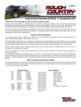
Jeep Grand Cherokee 93-98 ZJ 4” Longarm
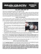
Thank you for choosing Rough Country for all your suspension needs.
Rough Country recommends a certified technician install this system. In addition to these instructions, professional
knowledge of disassemble/reassembly procedures as well as post installation checks must be known. Attempts to install
this system without this knowledge and expertise may jeopardize the integrity and/or operating safety of the vehicle.
Please read instructions before beginning installation. Check the kit hardware against the parts list on this page. Be sure
you have all needed parts and know where they go. Also please review tools needed list and make sure you have
needed tools. Always wear safety glasses.
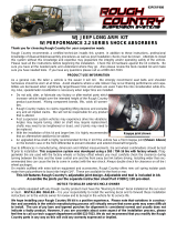
PRODUCT USE INFORMATION
Certain Rough Country Suspension products especially long arm kits are intended to improve off-road performance. The
addition of this kit may result in the vehicle handling differently than a factory equipped vehicle. As a rule seat belts and
shoulder harnesses should be worn at all times. Avoid situations where a side rollover may occur.
Generally, braking performance and capability are decreased when larger/heavier tires and wheels are used. Take this
into consideration while driving.
Do not add, alter, or fabricate any factory or after-market parts to increase vehicle height over the intended height of the
Rough Country product purchased. Mixing component brands is not recommended.
Rough Country makes no claims regarding lifting devices and excludes any and all implied claims. We will not be re-
sponsible for any product that is altered.
This kit features Rough Country’s adjustable joint design. Adjustable end tool is included in kit.
Assemble the joints per the separate instruction sheet Part # 92RCJ120 provided.
Due to inconsistency of vehicles when manufactures and various options available, the amount of actual lift gained by
this lift kit could vary. Muffler modification or off-road mufflers are required on this kit.
This suspension system was developed using a 31 x 10.50 x 15 tire with factory wheels. After market wheel will fit with
3 5/8” back spacing. Larger tire and wheel combinations may increase leverage on suspension, steering and related
components. Consider the additional stress you could be adding on the OE components, when selecting combinations
larger than OE. NOTICE TO DEALER AND VEHICLE OWNER
Any vehicle equipped with any Rough Country product should have a “Warning to Driver” decal installed on the inside of
the windshield or on the vehicle’s dash. The decal should act as a constant reminder for whoever is operating the vehi-
cle of its unique handling characteristics.
8mm wrench / socket
10mm wrench / socket
11mm wrench / socket
12mm wrench / socket
13mm wrench / socket
15mm wrench / socket
16mm wrench / socket
18mm wrench / socket
19mm wrench / socket
21mm wrench / socket
22mm wrench / socket
Floor Jack
Jack stands
Hammer
Reciprocating Saw
92190500
TORQUE SPECS:
Size Grade 5 Grade 8
3/8” 30 ft/lbs 35 ft/lbs
7/16” 45 ft/lbs 60 ft/lbs
1/2” 65 ft/lbs 90 ft/lbs
9/16” 95 ft/lbs 130 ft/lbs
5/8” 135 ft/lbs 175 ft/lbs
Class 8.8 Class 10.9
8MM 18ft/lbs 23 ft/lbs
10MM 32ft/lbs 45ft/lbs
12MM 55ft/lbs 75ft/lbs
14MM 85ft/lbs 120ft/lbs
9/16” wrench / socket
5/8” wrench / socket
3/4” wrench / socket
Crescent wrench
T55 Torx Head
T50 Torx head
Safety Glasses
Drill
11/32 drill bit
1/4” drill bit
15/32” drill bit
3/4” or step drill
WD40
Coil Spring Compressor
TOOLS NEEDED:

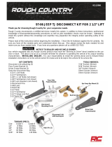
KIT CONTENTS
A A
B B
9288—Front Coil Spring (A)
9289—Rear Coil Spring (B)
1905BOX1 -
(12) Flag nuts (C)
93-95 Transmission Mount (D)
Skid Plate (E)
Rear Dr. Control Arm Bracket (F)
Rear Pass. Control Arm Bracket (G)
Sway Bar Disconnects (H)
Sway Bar Mounting Brackets (I)
1905BOX2 -
Front Dr. Lower Control Arm (J)
Front Pass. Lower Control Arm (K)
(2) Front Upper Control Arm (L)
1905BOX3 -
Crossmember (M)
1905BOX4 -
(2) Rear Lower Control Arm (N)
(2) Rear Upper Control Arm (O)
(2) Rear Bumpstop (P)
(2) Rear E-brake Bracket (Q)
Rear Track Bar Bracket (R)
1079G –Front Track Rod Kit
Front Adjustable Track Bar (S)
Front Track Bar Bracket (T)
PERF2.24ZJLA -
(2) 660585 Front Shock (U)
(2) 660584 Rear Shock (V)
C
C C
C
D
E
F G
H H
I I
J K
L
L
M
S
T
U
U
V
V
O O
N
R
N
P P
Q
Q

1905BAG1
In 1905BOX3:
4-10mm x 35mm Bolts
4-10mm Flat Washers
8-7/16” x 1 1/4” Bolt
10-7/16’ Flat Washers
2-3/8” x 3 1/2” Self Tapping Bolt
1905BAG2
in 1905BOX1
2-9/16” x 4” Bolts
4-9/16” Flat Washers
2-9/16” Lock Nuts
2-10mm x 80mm Bolts
2-10mm Lock Nuts
4-10mm Flat Washers
1905BAG3
in 1905BOX1
4-1/2” ID x 3 3/8” Long Crush Sleeves
4-1/2” x 5” Bolts
8-1/2” Flat Washers
4-1/2’ Lock Nut
4-7/16” x 1 1/2’ Bolts
4-7/16” Flat Washers
1905BAG4
in 1905BOX4
4-9/16” x 4” Bolts
8-9/16” Flat Washers
4-9/16” Lock Nuts
94000968BAG / 94000968BAG2 / ES505BAG
in 1905BOX1
2-1/2” Lock Nut
2-1/2” Flat Washer
2-1/2” Lock Nut
2-Double Wire Hitch Pin
2-3/8” x 1 1/4” Bolt
2-3/8” Lock Washer
4-5/16” x 1” Self Tapping Bolts
2-Upper Sway Bar Mounts
2-Lower Pins
2-3/8” Flat Washers
Continued...
1905BAG6
In 1905BOX1
4-3/8” x 1’ Bolts
4-3/8” Flange Lock Nuts
1905BAG7
In 1905BOX4
2-3/8” x 1 3/4” x 2 5/8” U-bolt
4-3/8” Flange Lock Nut
1-5/16” x 1 1/2’ Bolt
9-5/16” Flat Washers
1-Brake Line Clip
2-Cable Ties
4-5/16”x 1” Bolts
4-5/16” Lock Nuts
1-7/16” x 1’ Bolt
1-7/16’” Lock Nut
2-7/16’ Flat Washer
1-12mm x 65mm Bolt
1-12mm Flat Washer
1-12mm Flange Lock Nut
1-Crush Sleeve
4-3/8” x 1” Bolts
1905BAG8
In PERF2.24ZJLA Shock Box
2-Rear Lower Sleeves
2-Front Upper Stud Bushing Bags
1079- Front Track Bar Bracket Box
In 1079
1-Track Bar Sleeve
2-Track Bar Bushings
1-3/4” Jam Nut
2-7/16” x 2 3/4” Bolts
4-7/16’’ Flat Washers
2-7/16” Lock Nuts
2-Heim End Spacers
RCJ110Bag Large Joint Bags
& RCJ111Bag– Small Joint bags-Qty 4 each Bags
In 1905Box2 & 1905Box4
1-Threaded Ring
1-10/32”Set Screw
1-Flex Joint Flat Washer
1-Flex Joint Ball
2-Flex Joint Bushings
1-Snap Ring
1-1 1/4” Jam Nut
1-Grease Fitting
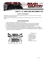
HARDWARE BAGS

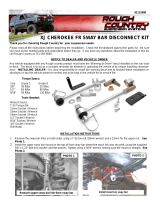
FRONT INSTALLATION
1. Place the vehicle on a level surface. Set the parking brake. Center the front wheels and chock the rear wheels.
2. From inside the engine compartment, using a 13mm deep well socket, remove the upper stud nut, washer and bush-
ings from the front shocks. See PHOTO 1.
3. Jack up the vehicle and place jack stands on the frame rail behind the lower control arm mount.
4. Remove the front tires/wheels, using a 13/16 deep well socket.
5. Place a floor jack underneath the axle for support and remove the lower shock bolts from the front shocks using a
13mm socket and wrench. Retain the factory lower bolts for reuse. See PHOTO 2.
6. Using a 15mm wrench and 18mm wrench for the upper bolt and a T55 torx head for the lower bolt, remove the sway
bar links. See PHOTO 3.
7. Remove the lower track bar bolt on the axle side and the upper track bar bolt on the frame side, using a 15mm
socket. See PHOTO 4.
8. Using a 13mm wrench remove the driver and passenger side coil retainer. Lower the axle and remove the coil
spring. A coil spring or strut compressor may be needed to remove the stock coil. Pull the ABS sensor wire from the
stock mount. Spray the line with WD40 to allow the mount on the wire to slide. See PHOTO 5.
9. Mark the original position of the eccentric cams on lower control arm. Using a 21mm socket & 18mm wrench remove
the stock lower bolt from the axle. Using a 21mm socket and wrench, remove the frame bolt from the lower control
arm. Retain the factory hardware fro reuse. See PHOTO 6.
10. Using a 15mm socket and T50 torx head, loosen and remove the upper control arms.
PHOTO 1 PHOTO 2
PHOTO 3 PHOTO 4
PHOTO 5 PHOTO 6
REMOVE SHOCK FROM THE UPPER MOUNT REMOVE SHOCK FROM AXLE
REMOVE THE SWAY BAR FROM THE AXLE REMOVE TRACK BAR BOLT
REMOVE COIL CLIP REMOVE THE LOWER CONTROL ARM

11. Remove lower control arm pockets with a cut off wheel. Cut down the dotted line as shown and along the back side
of the control arm pocket flush with the bottom of the uni-body. Grind down all welds and burrs, then paint to prevent
rusting. See PHOTO 7.
12. Place a jack or jack stand under the transmission, remove the 4 factory bolts holding the transmission mount to the
cross-member. Using a 15mm socket. See PHOTO 8. Next remove the 2 outer bolts on each side of the factory
cross-member, so the cross-member can be removed. Using a 15mm socket. See PHOTO 9. If the vehicle has a 2
bolt transmission mount the steps on page 14 must be followed prior to installing the new cross-member.
13. Install the new cross-member with 4 -10mm x 35 bolts using a 16mm wrench. See PHOTO 10.
14. Using the cross-member as a template, drill 4-15/32” holes (2 each side) on each front side of the cross-member.
See PHOTO 11.
15. Using the 4 short 7/16” thread flag nuts, insert two of them on each side of the cross-member. See PHOTO 12.
PHOTO 7
PHOTO 9 PHOTO 10
PHOTO 8
PHOTO 11 PHOTO 12

16. Install 4) 7/16” x 1 bolts and washers, tighten with a 5/8 socket. See PHOTO 13.
17. Next install the factory nuts on the cross-member holding the transmission mount with a 15mm socket.
See PHOTO 14.
18. Using a body saw cut out the opening for the flagnuts by following the outside profile of the dimple in the frame.
See PHOTO 15.
19. Using the cross-member as a template drill 4- 15/32” holes (2 Each Side) on each side of the factory 10mm bolts.
See PHOTO 16.
20. Using the 94003181 flag nut for the driver side rear hole and the 94003182 flag nut for the passenger side rear hole
as shown, tighten using a 7/16” x 1.25 bolt and washer and a 5/8 socket. See PHOTO 17. Note: The tabbed nuts
can be held with pliers.
21. Using the 94003179 flag nut for the driver side middle hole and the 94003180 flag nut for the passenger side middle
hole as shown. Tighten using a 7/16” x 1.25 bolt and washer and a 5/8 socket. See PHOTO 18. Note: The tabbed
nuts can be held with pliers.
PHOTO 13 PHOTO 14
PHOTO 15 PHOTO 16
PHOTO 17 PHOTO 18

22. Thread the assembled 1 1/4” flex joint into lower arm and adjust the arm length to 29 5/16” long center hole to cen-
ter hole. Install the control arm into the cross-member using the supplied 9/16” X 4 bolts, washers, and nylocks. See
PHOTO 19.
23. Insert the factory cam bolts into the rubber bushing end of the lower control arm, align the cam bolt markings made
earlier. Tighten both ends of the lower control arm with a 21mm wrench and a 22mm socket. See PHOTO 20.
24. Thread the assembled 3/4” flex joint into the upper control arm and adjust the arm length to 15 3/8” long center hole
to center hole. Install the upper control arm as shown, using the supplied 10mm x 80 bolts, washers, and nylocks.
See PHOTO 21.
25. Using the factory hardware bolt the upper control arm to the axle bushing as shown. Tighten both ends of the upper
control arm with a 12mm socket and wrench. See PHOTO 22.
26. Tighten the upper jam nut with a 1 1/8” wrench and the lower jam nut with a 1 7/8” wrench or cresent wrench.
27. Repeat steps 20-24 on the passenger side.
28. Using the 4 supplied 3/8” x 1 bolts install the cross-member skidplate with a 9/16” socket.
29. Remove the 4 bolts holding the factory track bar bracket with a 18mm socket. Retain hardware for reused.
30. Install the supplied track bar bracket on the frame with the factory fasteners. Tighten with a 18mm socket. See
PHOTO 23.
31. Install the sway bar link mounting bracket to the sway bar with a 3/8” x 1 1/4 bolt, washer, and lock washer. Tighten
with a 9/16 wrench. See PHOTO 24.
PHOTO 19 PHOTO 20
PHOTO 22 PHOTO 21
PHOTO 24 PHOTO 23

32 Install sway bar link into upper sway bar mounting bracket as shown. Tighten with a 18mm and 5/8 wrench. See
PHOTO 25.
33 Mount supplied disconnect pin to the axle bracket with 1/2” nylock and washer. Use a screwdriver through the hole
of the disconnect pin and a 19mm socket to tighten.
34 Next rotate the sway bar link up to hold the sway bar, mark and drill holes for the sway bar link mounting bracket
using a 1/4” drill bit. Install the 2 supplied 5/16” x 1 self tapping bolts. Tighten with a 1/2” socket, do not over tighten.
See PHOTO 26.
35 Drill a 11/32 hole in the center of the axle bumpstop pad.
36 Install the new coil springs with new 3” tall bump stop extention inside, using the supplied 3/8” x 3.5 self tapping
bolt. Tighten with a 9/16 wrench. Using a 13mm wrench install the driver and passenger side coil retainer. See
PHOTO 27.
37 Assemble the track bar with the bushing and sleeves in one end and the heims and jam nut on the other. Adjust the
bar length to 31 7/8” , then tighten jam nut with a 1 1/8” wrench. Using the 7/16” x 2 3/4 bolt, washer, and top-lock
attach the track bar bushing end to the frame bracket. Tighten with a 5/8 and 11/16 wrench. See PHOTO 28.
38 Assemble misalignment spacer into heims joint and bolt into the axle bracket using a 7/16” x 2 3/4 bolt, washer, and
nut. Tighten with a 5/8 and 11/16 wrench. See PHOTO 29. It may be necessary to lower vehicle to the ground to
align the bolt hole.
39 Assemble front shocks and install as shown with a 13mm wrench for the bottom and a 14mm wrench for the top
mount. See PHOTO 30.
40 Install the tires/wheels, using a 13/16” socket. Lower the vehicle to the ground.
PHOTO 26
PHOTO 28
PHOTO 29 PHOTO 30
PHOTO 25
PHOTO 27

REAR INSTALLATION
1. Chock the front wheels. Jack up the rear of the vehicle and support the vehicle with jack stands, so that the rear
wheels are off the ground.
2. Remove the rear tires/wheels, using a 13/16” deep well socket. Place a floor jack under the differential.
3. Remove the rear track bar from the frame mount on the passenger side using a 18mm wrench and T55 torx head.
Loosen the track bar on the axle side using a T55 and 18mm wrench.
4. Using a 18mm socket and a 15mm wrench, remove the rear shocks. Retain the shock hardware for reuse.
5. Using a 15mm socket disconnect the sway bar bracket from the frame. See PHOTO 1. Using a 8mm wrench for the
sway bar link and a 15mm wrench on the nut, remove the link from the axle. See PHOTO 2. The rear sway bar will
not be used in this kit.
6. Using a 13mm wrench remove the coil spring retainer. Retain factory hardware.
7. Lower the axle and remove the stock coil spring. A coil spring or strut compressor may be needed to remove the
stock coil.
8. Using a 21mm socket and wrench remove the lower control arm. See PHOTO 3. Retain the factory hardware.
9. Remove the brake line bracket from the drive side upper control arm with a 10mm wrench, next remove the brake
line clip holding the brake line to the bracket. See PHOTO 4 & 5. Discard the factory bracket.
10. With a 10mm wrench remove the e-brake bracket from the passenger side upper control arm. See PHOTO 6.
PHOTO 1
PHOTO 2
PHOTO 4
PHOTO 2
PHOTO 3
PHOTO 5 PHOTO 6

11. Remove the upper control arm using a 15mm wrench and a T55 torx head.
12. Remove the lower control arm pocket with a cut off wheel. Cut down the line shown in PHOTO 8 and along the back
side of the bracket flush with the bottom of the unibody. Grind down all welds and burrs, then paint to prevent rust-
ing.
13. Using a cutting blade remove the factory muffler, this muffler can not be used with the longarm kit. A smaller after-
market muffler is required. See PHOTO 9 &10.
14. With a 11mm socket remove the 5 rear nuts of the studs holding the heat shield to the bottom side of the body. This
will provide you will more room to cut off the rear upper control arm mounts. See PHOTO 11.
15. Remove the factory brake line bracket from the driver side upper control arm pocket with a 10mm wrench. Next re-
move the brake line clip so the line can be pulled out of the bracket. Take care not to kink or bind the steel line.
The two ABS wire will also nee to be removed from this bracket. This bracket is later re-installed on the control arm.
See PHOTO 12.
PHOTO 7 PHOTO 8
PHOTO 9 PHOTO 10
PHOTO 11 PHOTO 12

16. Using a cutting blade remove upper control arm mounting pockets, cut the pockets flush with the inside of the uni-
body. Grind down all welds and burrs, then paint to prevent rusting. See PHOTO 13.
17. Next install one of the 94003183 flag nuts on the driver side toward the rear and one of the 94003184 flag nuts to the
front. See PHOTO 14.
18. Using 2) 7/16” x 1.25 bolts and washers, bolt the upper control arm mount to the body. Tighten using a 5/8 socket
See PHOTO 15.
19. Using the bracket as a template drill through the body on both sides with a 17/32 drill bit. Next remove the bracket
with a 5/8 socket so that the outer holes can be enlarged. See PHOTO 16.
20. With a 3/4” drill bit or a step drill bit, open up the 2 outer holes of the body so a crush sleeve can be installed. See
PHOTO 17.
21. Using 2 of the 3/4 x 3 3/8 crush sleeves insert them into the outer drilled holes. It may be required to use a hammer
to install these sleeves. See PHOTO 18.
PHOTO 14 PHOTO 13
PHOTO 18 PHOTO 17
PHOTO 16 PHOTO 15

22. Using 2) 7/16” x 1.25 bolts and washers, bolt the upper control arm mount to the body. Tighten using a 5/8 socket.
Next install the 2) 1/2” x 5 bolts and washers through the bracket and crush sleeve. The bolt has to go in from the
outside, holding the 1/2” toplock nut in a 3/4 wrench slide the nut inside the cut out to tighten. See PHOTO 19.
23. Install the assembled 3/4” flex joint into the rear upper control arm, adjust the length to 39” center to center. Install
the rubber bushing end of the control arm into the frame bracket with a 9/16” x 4 bolt and washer. Holding the 9/16”
toplock nut with a 22mm wrench slide the nut inside the cut out. Hand tighten. See PHOTO 20.
24. Install the upper control arm into the axle mount with factory hardware with the head of the torx bolt towards the out-
side. Tighten with a 15mm wrench See PHOTO 21.
25. Install the 1 1/4” flex joint into the lower control arm , adjust the length to 38 7/8” center to center. Install the flex joint
end of the lower control arm to the frame bracket with a 9/16” x 4 bolt, washer, and nut. Tighten with a 21mm and
22mm wrench. See PHOTO 21.
26. Install the rubber bushing end of the lower control arm to the axle with factory hardware. Hand tighten. See PHOTO
23.
27. Tighten the upper jam nut with a 1 1/8” wrench and the lower jam nut with a 1 7/8” wrench or cresent wrench.
28. Repeat steps 17-27 on the passenger side.
29. Slide the 3/8 x 1 3/4 long u-bolt onto the control arm bolting up the brake line bracket. Tighten with 2) 3/8 flangelocks
and a 9/16 socket. See PHOTO 24. Next flip over the factory brake line bracket and use stock hardware to attach
with a 10mm wrench.
PHOTO 19 PHOTO 20
PHOTO 21 PHOTO 22
PHOTO 23 PHOTO 24

30. Using the supplied brake line bracket and 5/16” x 1.5 bolt, washer, and nut, bolt the brake to the body. Tighten with a
1/2” wrench. Next insert the brake line into the bracket and attach with the supplied brake line clip. See PHOTO 25.
31. Next unclip the ABS wire on the axle tube, pull the wire over the track bar bracket. This will allow enough slack for a
ABS wire not to pull tight when the suspension is extended. See PHOTO 26.
32. Use the 2 supplied cable ties to hold the ABS wires in place. See PHOTO 27 & 28.
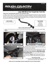
33. Install the new track bar bracket into the stock frame mount on the passenger side using the 7/16” x 1 bolt, washer,
and nut. Tighten using a 5/8 socket and wrench. Insert the crush sleeve inside the track bar bracket and bolt the
bracket to the frame using a 12mm x 65 bolt, washer, and flangelock. Tighten using a 19mm socket and wrench.
See PHOTO 29.
34. Install the bar with the stock hardware in the new bracket. Tighten with a 18mm wrench and a T55 torx torque to
50ft/lbs. See PHOTO 30. Installation on the axle can be completed with the vehicle on the ground.
PHOTO 26 PHOTO 25
PHOTO 28 PHOTO 27
PHOTO 30 PHOTO 29

35. Pull out the stock rear bump stops of the factory cup. Using a 13mm socket remove the 2 bolts holding the cups to
the frame.
36. Install the extended bump stop bracket with the stock bolts. Make sure the bracket is angled to the rear axle. Tighten
with a 13mm socket. See PHOTO 31.
37. Bolt the factory cup to the bump stop with the supplied 5/16” x 1 bolts, washer, and nylocks. Tighten with a 1/2”
wrench and socket. See PHOTO 32.
38. Install the bump stop into the factory cup. See PHOTO 33.
39. Install the new coil spring, a coil spring compressor may be needed to install the new coil. Locate the factory coil
spring clip and tighten using a 13mm wrench. See PHOTO 34.
40. Assemble the rear shock part # 660584 with the supplied sleeves. Install the shock as shown with factory hardware,
using a 18mm socket on the top and a 15mm wrench and 18mm socket on bottom. See PHOTO 35 & 36.
41. Install the tires/wheels and lug nuts using a 13/16” socket., then lower the vehicle to the ground.
42. Using a 21mm and 22mm wrench tighten the rubber bushing on the upper and lower control arms.
43. Align the track rod with the axle mount by using a floor jack and install the track rod on the axle using factory hard-
ware.
PHOTO 32
PHOTO 31
PHOTO 33
PHOTO 35
PHOTO 34
PHOTO 36

2 BOLT TRANSMISSION MOUNT
1. Using a 18 and 19mm wrench remove the bolt holding the transmission mount as shown. See PHOTO 1 & 2. Retain
stock hardware for reuse.
2. Next bolt the supplied transmission mount to the cross-member using the 4 supplied 3/8” x 1 bolts and flange locks.
Tighten with a 9/16” socket and wrench. See PHOTO 3.
3. Install stock hardware using a 18mm and 19mm wrench. See PHOTO 4.
PHOTO 4 PHOTO 3
PHOTO 2 PHOTO 1

Thank You for Purchasing a Rough Country Suspension System
1. Check all fasteners for proper torque. Check to ensure there is adequate clearance between all rotating, mobile,
fixed and heated members. Check steering for interference and proper working order. Test brake system.
2. Perform steering sweep. The distance between the tire sidewall and the brake hose must be checked closely. Cycle
the steering from full turn to full turn to check for clearance. Ensure there is adequate clearance between exhaust
and brake line, fuel lines, fuel tank, and wiring harnesses. Failure to perform inspections may result in component
failure.
3. Check clearance between the inner side wall of tires and links. It may be necessary to adjust steering stops.
4. Re torque all fasteners after 500 miles. Visually inspect components and re torque fasteners during routine vehicle
service.
5. Readjust headlights to proper settings.
6. Vehicle will have to have an alignment.
7. Some vehicles may experience drive line vibrations. Angles may require tuning, shafts may need to be lengthened
or trued, and u-joints may need to be replaced.
POST INSTALLATION
It is the ultimate buyers responsibility to have all bolts/nuts checked for tightness after the first 500 miles and then every
1000 miles. Wheel alignment steering system, suspension and driveline systems must be inspected by a qualified pro-
fessional mechanic at least every 3000 miles.
MAINTENANCE INFORMATION
-
 1
1
-
 2
2
-
 3
3
-
 4
4
-
 5
5
-
 6
6
-
 7
7
-
 8
8
-
 9
9
-
 10
10
-
 11
11
-
 12
12
-
 13
13
-
 14
14
-
 15
15
-
 16
16


Ask a question and I''ll find the answer in the document
Finding information in a document is now easier with AI
Related papers
-
 Rough Country 90222 Installation guide
-
 Rough Country 90820 Installation guide
-
 Rough Country 90900U Installation guide
-
 Rough Country Front Sway Bar Quick Disconnects Installation guide
-
 Rough Country 900.20 Installation guide
-
 Rough Country Front Sway Bar Quick Disconnects Installation guide
-
 Rough Country Front Sway Bar Quick Disconnects Installation guide
-
 Rough Country 1188 Installation guide
-
 Rough Country 3.25in Suspension and Spacer Lift Kit Installation guide
-
 Rough Country 10512 Installation guide


Other documents
-
 Teraflex Front Swaybar Quick Disconnects Installation guide
-
Lynx Front & Rear Control Arm Kit Installation guide
-
 Teraflex 001744000 Installation guide
-
Skyjacker C7661A Installation Instructions Manual
-
 Belltech 150210BK Installation guide
-
-
-
-
Belltech 150203HK Installation guide
-
 Fishbone Offroad FB25314 Installation guide


