Page is loading ...

Before beginning the installation, read these instructions and the enclosed driver’s WARNING
NOTICE thoroughly and completely. Also affix the WARNING decal in passenger compartment in
clear view of all occupants. If any of these items are missing from this instruction packet, do not pro-
ceed with installation, but call SKYJACKER®to obtain needed items. If you have any questions or
reservations about installing this lift kit, call SKYJACKER®at 318-388-0816 for Technical Assistance
or Customer Service departments.
Make sure you park the vehicle on a level concrete or asphalt surface. Many times a vehicle is
uneven (side-to-side) from the factory, but usually not noticed until a lift kit has been installed which
makes the difference more visible. Using a measuring tape, measure the front and rear (both sides)
from the ground up to the center of the fender opening above the axle. Record below for future ref-
erence.
Driver Side Front: Passenger Side Front:
Driver Side Rear: Passenger Side Rear:
IMPORTANT NOTES:
• Skyjacker recommends the use of 245/75R16 tires, 30 1/2" tall, which can be mounted on
the factory wheels. 255/75R16 tires may also be used, but some inner fender wheel well
trimming may be necessary.
• Please refer to Parts List to insure that all parts and hardware are received prior to disassembly of
vehicle. If any parts are found to be missing, contact your dealer as soon as possible.
•If larger tires (10% more than stock diameter) are installed, speedometer recalibration is necessary
(see Jeep dealer or Tire Store).
•This lift is determined from the front while only lifting the rear to a position level with the front.
•After installation occurs, a qualified alignment facility is required to align the vehicle.
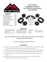
02-07 Jeep Liberty 2WD/4WD
2.5” Suspension lift
Installation Instructions
Part # LIB250K
REQUIRED TOOL LIST:
* Metric and Standard wrenches and sockets
* Allen Wrenches
* Assorted Drill Bits
* Floor Jack
* Jack Stands
* Measuring Tape
* Coil Spring Compressor
* Torque Wrench
www.skyjacker.com
I-LIB250 11-07 Pg 1

Kit Box Breakdown:
LIB250:
ITEM# DESCRIPTION Qty
LIB25FS LIBERTY FRONT COIL 2.5" 2
9050S FRONT STRUT - LIBERTY 2
LSM279 LIBERTY ALUMINUM COIL MOUNT,LIB250 2
38FTN 3/8-24 FINE N/I LOCK NUT 2
BPS20-B BUMP STOP SPACER BLACK, 2" 2
10MMX70MMB 10 X 70 METRIC BOLT/10.9 2
10MMN 10 MM N/I LOCKNUT 2
LBS3383 LIBERTY KJ BUMP STOP, FRONT 2
Front Installation:
1. Block the rear tires. Raise the front of the vehicle using a floor
jack, support the frame rails using jack stands. Remove the
tires and wheels.
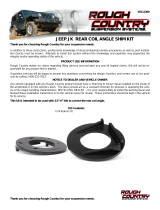
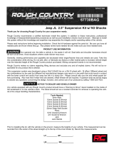
2. Remove the brake caliper using a 21mm wrench. Once caliper
is removed, remove rotor. (See Photo #1) Wire caliper out of
the way until reinstallation. It will not be necessary to discon-
nect the brake line from the caliper.
3. Remove outer axle nut using 1 7/16” socket. (See Photo #2)
4. Remove ABS line from steering knuckle using a 5mm allen
wrench. (See Arrow in Photo #3)
5. Disconnect the sway bar link from the Lower A-Arm using a
18mm wrench.
6. Remove the tie rod end nut from knuckle using 21mm socket.
Remove the tie rod end from the knuckle by striking the knuck-
le to dislodge the tie rod end. Be careful not to damage the tie
rod end. (See Photo #4)
7. Remove upper and lower A - Arm ball joints from knuckle using
21mm socket. Once again it may be necessary to strike the
knuckle to allow the tie rod end to dislodge. Remove knuckle
from vehicle. (See Photo #5) Be sure not to remove the C.V.
shaft from the differential.
8. Disconnect the lower bolt on clevis bracket from the Lower A-
Arm using a 21mm socket. (See Photo #6)
9. Remove the battery from the vehicle. Unbolt the battery tray
and move aside. Remove the upper 4 retaining nuts from the
upper strut bracket using an 18mm socket.
Photo #1
Photo #2
Photo #3
Photo #4 Photo #5 Photo #6
I-LIB250 Pg 2

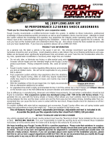
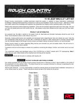
10. Remove the upper bolt on the clevis bracket using a 21mm
socket. (See Photo #7) Remove the clevis bracket and remove
the strut from vehicle. (See Photo #8)
11. Using a coil spring compressor, disassemble the factory strut
assembly. The upper mounting bracket and retaining washer
will be reused.
12. Slide the new coil spring over the new strut assembly. Be sure
that the coil spring sits flush against the new aluminum seat on
the shock. Attach the factory upper bracket to the new
coil/shock assembly using a coil spring compressor.
Important Note! Using a wrench or ratchet, install the 3/8”
nylon-insert lock nut on shock stem first and torque to 15-
17 Ft. Lbs, then double nut by tightening the 3/8” standard
hex nut against the nylon lock nut and torque to 14-16 Ft.
Lbs. NOTE: Do NOT use an air impact to install nuts as
this will strip the threads. Be sure coil is seated properly in
upper and lower seat. (See Photo #9 and #10)
Upon Installation of the Coil Assembly, use caution,
Be Sure not to damage the factory Inner C.V. Boot!
13. Install the new coil assembly. First attach the upper mount
using the factory hardware removed earlier. Do not tighten
these bolts at this time. Attach the lower clevis bracket onto the
bottom of the new coil assembly using factory hardware.
Torque to 65 Ft. Lbs. (See Arrow in Photo #11) Attach to the
Lower A-Arm using factory hardware. It may be necessary to
loosen the lower A-Arm to allow it to slide outward and bolt up
to the clevis bracket. Be sure to mark Cam Washers so they
can be set back in the same position. (See Photo #12) With all
bolts started, tighten all bolts at this time. Once the upper
bracket has been tightened, reattach battery tray and reinstall
battery.
14. Using a floor jack raise the lower A-Arm so that the steering
knuckle can be reinstalled. Slide C.V. shaft through factory
steering knuckle. Attach steering knuckle to upper and lower A-
Arm using factory hardware. Torque to factory Specs. Be sure
to reinstall outer tie rod and ABS line to the steering knuckle.
15. Remove the factory rubber bump stop off of the frame. They
can be easily removed with the use of a pair of pliers. Install
the new polyurethane bump stop in the factory position by tap-
ping in with a hammer. The bump stop may be easier to install
if it is first sprayed with WD-40. (See Arrow in Photo #13)
Photo #7
Photo #8
Photo #10
Photo #11 Photo #12
I-LIB250 Pg 3
Photo #13
Photo #9
3/8” Nylon Lock Nut
3/8” Standard Hex Nut

Rear Installation:
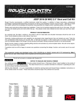
16.With vehicle on flat level ground, set the emergency brake
and block the front tires. Raise the rear of the vehicle using
floor jack. Support the frame rails using jack stands. Remove
the rear tires and wheels. Remove the rear shocks using
15mm and 18mm wrench. (See Photo #14)
17. Lower the rear axle far enough to allow for removal of the
rear coil spring. (See Photo #15)
18. Locate the bump stop contact pad on the rear axle. Locate
center of the pad and make a mark. (See Photo #16)
19. Once mark is made, drill this point using a 13/32” drill bit. Be
sure not to drill into the axle tube. (See Photo #17)
20. Install new coil spring first, once coil is installed, install the
new bump stop extension using the 10mm x 70mm bolt and
nut supplied. (See Photo #18)
21. With the coil spring and bump stop installed, raise the rear
end back up, install new shocks. (See Photo #19). Reinstall
tires/wheels and let the weight of the vehicle on to the
ground.
Photo #14
Photo #15
Photo #16
Photo #17
Photo #19Photo #18 Pg 4

I-LIB250 Pg 5
FINAL NOTES:
• After installation is complete, double check that all nuts and bolts are tight.
• If new tires are installed that are more than 10% taller than original tires, the speedometer must be
recalibrated. Contact an authorized Jeep dealer for details on recalibration.
• With the vehicle on the floor, cycle steering lock to lock and inspect steering, suspension and driv-
eline systems for proper operation, tightness and adequate clearance. Recheck brake hose/fittings
for leaks.
• Have headlights readjusted to proper settings.
• Have a qualified alignment center realign front end. Be sure vehicle is at desired ride height prior
to realignment.
• Retorque all bolts after the first 100 miles.
Seat Belts Save Lives, Please Wear Your Seat Belt.
/