Page is loading ...

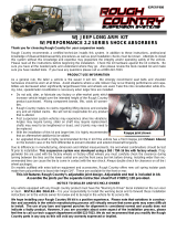
WJ JEEP LONG ARM KIT
92PERF908
Thank you for choosing Rough Country for your suspension needs.
Rough Country recommends a certified technician installs this system. In addition to these instructions, professional
knowledge of disassemble/reassembly procedures as well as post installation checks must be known. Attempts to install
this system without this knowledge and expertise may jeopardize the integrity and/or operating safety of the vehicle.
Please read all the instructions before beginning the installation. Check the kit hardware against the kit contents. Be
sure you have all the needed parts and understand where they go. Also please review the tools needed list and make
sure you have needed tools. If you have any questions please call us at 800-222-7023.
PRODUCT USE INFORMATION
As a general rule, the taller a vehicle is the easier it will roll. We strongly recommend seat belts and shoulder
harnesses should be worn at all times. Avoid situations where a side rollover may occur. Braking performance and capa-
bilities are decreased when significantly larger/heaver tires and wheels are used. Take this into consideration while driv-
ing. Also, speedometer recalibration is necessary when larger tires are installed.
• Do not add, alter, or fabricate any factory or after-market parts which
increase vehicle height over the intended height of the Rough Country
product purchased. Mixing component brands, lifts, voids all warran-
ties.
• Rough Country makes no claims regarding lifting devices and excludes
any and all implied claims. We will not be responsible for any product
that is altered.
• Post suspension system vehicles may experience drive line vibrations.
Angles may require tuning, slider on shaft may require replacement,
shafts may need to be lengthened or trued, and U-joints may need to
be replaced.
• With the installation of this kit and larger tires it is highly recommended
that an aftermarket stabilizer(s) be added.
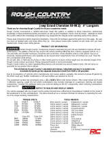
• An upgraded drive-shaft is highly recommended for the 4’ kit if the vehicle has a front rizeppa joint (Shown Above)
on the transfer case or the front differential to prevent vibration and extend driveshaft longevity.
Due to differences in manufacturing, dimension and inflated measurements, tire and wheel combinations should be test
fit prior to installation. This suspension system was developed using a 265 / 75R-16 tire with factory wheels. If big-
ger/wider tire are used with the factory wheels or factory offset wheels you must carefully check the clearance during
turning between the tires and the lower control arm and the front sway bar link before driving. Installing wider than rec-
ommended tires can cause the tire to come in contact with the rear shock. Always double check for clearance on all tire /
wheel packages.
On models outfitted with extra bolt-on equipment and accessories, Rough Country offers new coil spring isolator pads
made from polyurethane to boost ride height 3/4". These are available for the front or rear.
NOTICE TO DEALER AND VECHICLE OWNER
Any vehicle equipped with any Rough country product must have the “Warning to Driver” decal installed on the sun visor
or dash. INSTALLING DEALER—It is your responsibility to install the warning decal and to forward these installation
instructions on to the vehicle owner for review and to be kept in the vehicle for its service life.
We hope installing your Rough Country lift kit is a positive experience. Please note that variations in construc-
tion and assembly in the vehicle manufacturing process will virtually ensure that some parts may seem difficult
to install. The use of pry bars and tapered punches for alignment is considered normal and usually does not
indicate a faulty product. However, if you are uncertain about some aspect of the installation process, please
feel free to call our tech support department at 800-222-7023. We do not recommend that you modify the Rough
Country parts in any way as this will void any warranty expressed or implied.
Rzeppa joint shown
*1908B1*
1908B1

1698C-4” KIT
Fr Coil Springs (A)
Rr Coil Spring (B)
1908BOX5:
1-Crossmember ©
4-Lower Flex Joints
1908Box6:
2-Transmission Bracket (D)
1-Skid Plate (E)
4-Front Frame bracket flag nuts (F)
2-Fr Axle Brake Bracket (G)
2-Fr Bump Stop Brackets (H)
2-Front Sway Bar Links (I)
1-Rear L/A Axle Mount (J)
1-Dr Rear Frame Bracket (K)
1-Pass Rear Frame Bracket (L)
4-Rr Frame Bracket Flag Nuts (M)
2-Rear Sway Bar Brackets (N)
2-Rear Lower Shock Brackets (O)
2-Upper Flex Joints
1908.3:
2-Rear Lower Long Arm (P)
1-Dr Front Lower Long Arm (Q)
1-Pass Front Lower Long Arm (R)
1-Dr Upper Adj Front Arm (S)
1-Pass Upper Adj Front Arm (T)
1908Box7:
1-Rear Upper Y-Link (U)
1-Upper Y-Link Flex Joint
1084 Front Track Rod:
1-Track Rod Body (V)
1-Heim End
1084Poly Bag Containing:
Heim End Spacers (2)
Bushings (2)
Sleeve
12mm x 65mm Bolt
Flat Washer
12mm Lock nut
Jam Nut
1908Bag1:
Instruction Sheet Bag
1908Bag2:
For Front Cross-member:
4-10m x 80mm Bolts
4-10mm x 35mm Bolts
8-10mm Flat Washers
4-7/16” x 1 1/4” Bolts
4-7/16” Flat Washers
For Transmission Mount:
4-7/16” x 1 1/4” Bolts
For Skid Plate:
4-5/16” x 1 1/4” Bolts
4-5/16” Flat Washers
For the Front Lower Control Arm:
2-9/16” x 4 1/2” Bolts
2-9/16” Lock Nuts
4-9/16” Flat Washers
For Front Bump stop:
2-8mm x 95mm Bolts
2-8mm Flat Washers
For Front Axle Brake Line Brackets:
2-1/4” x 1” Bolt
2-1/4” Lock Nuts
4-1/4” Flat Washers
For Lower Shock Bolts:
4-5/16” x 1” Bolts
4-5/16” Lock Nuts
8-5/16” Flat Washers
1131Bag:
For Front Sway Bar Disconnects:
2-1/2” Lock nuts
2-Hitch Pins
2-1/2” Flat washers
2-Disconnect Mounting Pins
2-12mm Flange Lock Nuts
2-12mm Jam Nuts
2-Rod Ends
2-Crush Sleeves
2-Frame Brackets
1908Bag3:
For Rear Control Arm Mounts:
8-1/2” x 1 1/2” Bolts
8-1/2” Flat Washers
For Rear Arm Axle Mount:
3-14mm x 50mm Bolts
3-14mm Flat Washers
For Rear Lower Control Arm:
2-9/16” x 4 1/2” Bolts
2-9/16” Lock Nuts
4-9/16” Flat Washers
For Rear Upper Y-Link:
1-9/16” x 4 1/2” Bolt
1-9/16” Lock Nut
2-9/16” Flat Washers
For Rear Upper Brake Brackets:
4-1/4” x 3/4” Bolts
4-1/4” Lock Nuts
8-1/4” Flat Washers
For Rear Sway Bar Brackets:
4-10mm x 90mm Bolts
4-10mm Flat Washers
For Rear Bump stop:
2-3/8” x 3 1/4” Self Tap Bolts
1908Bag4: Containing
For Rear Lower Shock Mount:
2-12mm x 100mm Bolts
2-12mm Sleeves
2-12mm Flat Washers
1639Box1:
2-3.0 Series Front Shock (W)
2-3.0 Series Rear Shock (X)
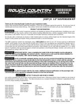
KIT CONTENTS
This kit is packaged in 7 boxes. Please makes sure you have all the need parts and understand where they go prior to
beginning installation. Please use the attached picture to match parts to their descriptions shown below.

KIT CONTENTS
A
A
B
B
C
D
E
F
G
G
H
H
I
I
J
K
L
M
M
N
N
O
O
P
P
Q
R
S
T
U
V
W
W
X
X

IMPORTANT PRE—INSTALLATION INSTRUCTIONS
Prior to beginning this installation it is always good to use a penetrating oil and spray all fasteners that will be re-
moved. TOOLS NEEDED:
Prior to beginning installation please re-read the instructions and make sure you have all the tools needed to com-
plete installation. Listed below are the minimum tools required.
• Spring Compressor
• Silicone spray
• Drill assortment
• Hammer
• Combination wrenches
• Torx bit socket
• File / Grinder
• Floor jacks
• Wheel chocks
• 1/2” drill motor
• 15/32” Drill bit
• 17/32” Drill bit
• 1/2 drive ratchet and sockets
• Allen wrenches
• Large “C” clamps and /or bench vise ( For Joint Assembly)
• Heavy duty jack stands
• Safety glasses
• Anti-seize compound
TORQUE SPECS:
Listed below are generic torque specs that are to be used when no specific spec is listed in the instructions. Please
note it is extremely important to tighten all fasteners to the proper specs.
Size Grade 5 Grade 8
5/16” 15 ft/lbs 20 ft/lbs
3/8” 30 ft/lbs 35 ft/lbs
7/16” 45 ft/lbs 60 ft/lbs
1/2” 65 ft/lbs 90 ft/lbs
9/16” 95 ft/lbs 130 ft/lbs
5/8” 135 ft/lbs 175 ft/lbs
3/4” 185 ft/lbs 280 ft/lbs

FRONT INSTALLATION INSTRUCTIONS
1. Chock the rear wheels and jack up the front of the vehicle and support the vehicle with jack stands.
2. Support the front axle with a floor jack.
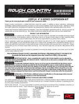
3. Remove the lower sway bar link from the axle and the sway bar using a 15mm & 18mm wrench. See Photo 1.
4. Remove the shocks using a 15mm wrench/socket for the top mount and a 13mm wrench/socket for the bottom
mount.
5. Lower the axle using the floor jack and remove the coil springs.
6. Remove the stock lower control arm using a 21mm wrench/socket. Retain factory hardware for re-use See Photo 2.
7. Remove the stock upper control arms using a torx bit and a 18MM wrench.
8. Remove the track bar using a 19mm wrench/socket from the driver side mount as shown in Photo 3 and remove
from the axle using a 15mm socket. Retain the axle hardware for reuse.
9. Remove the brake line bracket from the driver and passenger side frame using a 10mm socket. Retain the hardware
for reuse. See Photo 4.
10. Remove the lower control arm mount from the driver and passenger side flush with frame using a cut off wheel or
reciprocating saw. See Photo 5.
11. Grind smooth and paint to prevent rusting. See Photo 6.
Photo 1
Remove Lower Sway Bar Link from Axle Mount Remove Lower Control Arm
Photo 2
Photo 3
Remove Track Rod from Driver Side
Photo 4
Remove Brake Line Bracket
Photo 5 Photo 6
Remove the lower front control arm mounts Grind and paint the area

12. Remove the bolt in the center of the cross member securing the transmission to the cross member using a 15mm
socket / wrench. Retain the center bolt for reuse.
13. Support the transmission and remove the cross member by removing the 4 bolts on each side using a 15mm socket.
See Photo 7.
14. Lower the cross member away from the frame.
15. Install the new transmission mount as shown in Photo 8 using the factory hardware. Do not tighten at this time.
16. Place the new cross member on the frame and install using supplied 10mm x 80mm bolts in the outside holes and
the 10mm x 35mm on the inside holes. Tighten using a 15mm socket. See Photo 9.
17. Using bracket as a guide, cut a hole using a 1 1/4” hole saw. See Photo 10.
18. Using the bracket as a guide drill the two holes using a 15/32” drill bit. See Photo 11.
19. Insert the supplied flag nuts and secure with the supplied 7/16” x 1 1/4” bolts and flat washers. See Photo 12. Tight-
en using a 5/8” socket.
Photo 7
Remove Bolts from Cross Member
Photo 8
Remove Bolts from Cross Member
Remove Bolts from Cross Member
Photo 9
Remove Bolts from Cross Member
Photo 10
Photo 11
Drill the holes using a 15/32” drill bit
Photo 12
Insert the flag nuts and secure with 7/16” bolts

20. Secure the cross member to the transmission mount using the supplied 7/16” x 1 1/4” bolts. Tighten using a 5/8”
socket. See Photo 13. Tighten the stock transmission bolt.
21. Install the skid plate on the cross member using the supplied 5/16” x 1 1/4” Bolts. See Photo 14. Tighten using a
1/2” socket.
22. Adjust the lower control arm to a measurement of 29 3/4” from center of eye to center of joint and install the lower
long arm in the mount. Secure with the supplied 9/16” x 4 1/2” bolts, flat washers and lock nut. Do not tighten at this
time. See Photo 15.
23. Swing up the lower arm and install on the axle using the factory hardware. Do not tighten at this time.
24. Install the upper arm on the lower arm with the supplied 10mm x 80mm bolt, flat washer and lock nut.
25. Adjust the upper arm to a measurement of 14 5/8” from center of hole to center of joint and install on the axle making
sure to place the arm on the axle correctly with the cutout down for clearance. Secure with the supplied 10mm x
80mm bolts, flat washers and lock nuts. See Photo 16.
26. Remove the bump stop from the cup and remove the cup from the frame using a 13mm socket. See Photo 17.
27. Install the spacer bracket and reinstall the factory cup using the supplied 8mm x 95mm bolts and flat washers. See
Photo 18. Tighten using a 1/2” socket. Reinstall the rubber bump stop in the cup.
Photo 14
Install the skid plate on cross member
Photo 13
Secure the cross member to the trans mount
Photo 15 Photo 16
Install the lower arm on the cross member Install the upper arm
Photo 17 Photo 18
Remove the bump stop cup Reinstall the cup with spacer bracket

28. Remove the stock coil isolator from the lower end of the stock coil and reinstall on the lower end of the new coil. See
Photo 19.
29. Install the new coil in the lower and upper spring seats.
30. Install supplied pin on the axle with supplied crush sleeve in stock mount. See Photo 20. Hold using a screwdriver &
tighten 1/2” lock nut using a 3/4” wrench.
31. Assemble the sway bar link with the link body, the jam nut and rod end Adjust the sway bar to a length of 11 1/4”
from top to bottom. Tighten the jam nut against the rod end using a 19mm & 5/8” wrench.
32. Install the sway bar link on the upper sway bar mount with the supplied 12mm flange lock nut. See Photo 21. Tight-
en using a 18mm & 5/8” wrench.
33. Remove the stock bolt from the vehicle on both driver and passengers side and install the sway bar bracket with
stock hardware. Tighten bolt using a 15mm wrench. See Photo 22.
34. With the sway bar link installed on the supplied frame bracket, swing the bracket and sway bar link up and position
the bracket on the frame as shown in Photo 23.
35. Install on the lower axle mounting pin. Install the disconnect hitch pin. See Photo 24. Note: When disconnected the
hitch pin will be used on the upper mount to secure the sway bar link to the mount.
Photo 19
Reinstall the lower coil isolator on ne coil
Photo 24
Install the sway bar link on the axle with hitch pin
Photo 20
Photo 21
Install the link on the mount
Photo 22
Place the mount on the uni-body
Photo 23
Install the pin on the axle
Link shown on upper link bracket

36. Remove the driver and passenger brake line bracket from the axle using a 10mm socket. See Photo 25.
37. Install the brake line bracket on the axle using the factory bolt. Tighten using a 10mm socket. See Photo 26.
38. Reinstall the brake line on the new bracket using the supplied 1/4” x 1” bolt, flat washer and lock nut. Tighten using a
11mm socket / wrench. See Photo 27.
39. Reinstall the brake line bracket on the frame that was removed in Step# 4. Tighten using a 10mm socket.
40. Install the shock absorbers using the supplied 5/16” x 1” bolts, flat washers, lock nuts in the lower and the bushings/
cup washers and nuts on the upper. Tighten the lower using a 1/2” socket / wrench on the lower and the upper using
a 9/16” socket. See Photo 28.
41. Install the tires and wheels.
42. Jack up vehicle, remove the jack stands and lower the vehicle to the ground.
43. Locate the track bar and lubricate the supplied bushings / sleeves with a lithium grease and assemble the bushings
and sleeves in the track bar end.
44. Install the track bar on the axle mount with the factory hardware. See Photo 29. Do not tighten at this time.
45. Assemble the spacers on the heim joint as shown in Photo 30.
Photo 25 Photo 26
Photo 27
Remove the axle brake line mount Install the brake line bracket
Install the brake line to bracket Install the shock absorber
Photo 28
Photo 29 Photo 30
Install the track rod on the axle Install the supplied spacers

46. Make sure the body of the vehicle is centered over the axle and adjust the end as needed and install the end on the
frame with the supplied 12mm x 65mm hardware. Do not tighten at this time. See Photo 31.
47. After making sure the body is centered, tighten the jam nut using a 1 1/8” wrench on the track rod end. Note**
Make sure flex joint housing is centered in mount before tightening jam nut. Should not be touching either
side.**
48. Tighten the frame end with a 18mm & 19mm wrench and
on the axle end with a 15mm socket.
49. Tighten lower arm axle hardware using a 21mm socket /
wrench.
50. Tighten the lower arm frame mount using a 21mm &
22mm socket / wrench.
51. Tighten the upper arm hardware using a 17mm socket /
wrench.
Photo 31
Install on the frame with 12mm x 65mm Bolt

REAR INSTALLATION INSTRUCTIONS
1. Chock the front wheels.
2. Jack up the vehicle and place the vehicle on jack stands.
3. Support the rear axle with a floor jack.
4. Remove the lower control arms using a 21mm socket / wrench. Retain the stock hardware.
5. Remove the 4 brake line brackets securing the brake lines on the upper arm using a 13mm socket. See Photo 2.
6. Remove the upper arm hardware using a 21mm socket. See Photo 3.
7. Remove the arm from the differential using a 15mm wrench and remove the arm from the vehicle. See Photo 4.
8. To ease installation of new drop brackets, remove the two exhaust hanger bolts shown in Photo 5 on the passenger
side using a 13mm socket and let exhaust hang. Secure to make sure the exhaust does not over extend and dam-
age the exhaust system.
9. Using a cut off wheel or reciprocating saw as shown in Photo 6 remove the lower arm mounts.
10. Grind the mount and paint to prevent rusting.
Photo 5
Remove the exhaust hanger bolts
Photo 1
Remove the lower rear arms
Photo 2
Remove the brake lines from the upper arm
Photo 3 Photo 4
Remove the arm from the frame Remove the arm from the axle
Photo 6
Cut the lower mounts from the frame

11. Locate the hole on the frame as shown in Photo 7.
12. Place the bracket on the frame as shown and align the two holes in the bracket on the passenger side. The Driver
side will align with the large hole. The two small holes are not present on the driver side. Enlarge / Drill the
holes using a 17/32”. See Photo 8. The holes must be aligned prior to drilling!!
13. Insert the supplied flag nuts in the frame as shown in Photo 9. Needle nose pliers will aid in the installation of these
flag nuts.
14. Secure with the supplied 1/2” x 1 1/2” bolts and flat washers. Tighten using 3/4” socket. See Photo 10.
15. Reposition the brake line as shown to prevent damage while drilling. See Photo 11.
16. Measure 4 1/4” from the center of hole and mark. See Photo 12.
Photo 7 Photo 8
Photo 9 Photo 10
Locate the hole in the frame Align holes and enlarge holes
Insert flag nuts in the frame Secure using 1/2” bolts
Photo 11
Unclip and reposition line
Photo 12
Measure 4 1/4” over

17. Measure up 1 1/4” from the bottom of the frame as shown and mark. See Photo 13.
18. Using bracket as a guide, drill holes using a 17/32” bit. See Photo 14. Use caution when drilling close to fuel or
brake lines!!
19. Drill the marked holes front and rearward of the bracket using a 1 1/4” hole saw. See Photo 15.
20. Photo 16 shows the holes in the frame.
21. Paint may be applied to the holes to prevent rusting
22. Insert the flag nuts in the frame and secure the bracket using the supplied 1/2” x 1 1/2” Bolts and flat washers. See
Photo 17 & 18. Tighten using a 3/4” socket.
23. Reinstall the brake lines in the clips on the frame.
Photo 13 Photo 14
Photo 15 Photo 16
Measure 1 1/4” up from bottom of frame Drill using a 17/32” bit
Drill using a 1 1/4” hole saw Drilled holes shown
Photo 17 Photo 18
Insert flag nuts in the frame Secure using 1/2” x 1 1/2” Bolts

24. Install the differential bracket as shown using the 14mm x 50mm bolts and flat washers. See Photo 19. Tighten us-
ing a 7/8” wrench.
25. Adjust the arm to a measurement of 34 1/2” from center of eye to center of eye and tighten jam nut.
26. Install the lower arm in the frame bracket using the supplied 9/16” x 4 1/2” bolts, flat washers and lock nuts. See
Photo 20. Do not tighten at this time.
27. Install the lower arm on the axle using the stock hardware. See Photo 21. Do not tighten at this time.
28. Assemble the rear upper y-link with the flex joint to a measurement of 7 3/8’ from the flat edge of the center brace to
the center of the flex joint. Install the new y-link in the factory location on the frame using the factory hardware and
tighten using a 15mm socket. See Photo 22.
29. Install the Y-link to the new axle bracket with the supplied 9/16” x 4 1/2” Bolt, flat washers and lock nut. See Photo
23. Tighten using a 21mm x 22mm socket / wrench.
30. Reinstall the brake line brackets to the tabs on the Y-link arm with the supplied 1/4” x 3/4” bolts, flat washers and
lock nuts. See Photo 24.
Photo 19
Install the differential bracket Install the rear lower arm in the frame bracket
Photo 20
Photo 21 Photo 22
Photo 23
Install the rear lower arm on the axle Install the upper arm on the frame
Install the upper arm on the axle bracket Reinstall the stock brake line brackets on tabs
Photo 24

30. Remove the sway bar bracket from the frame using a 15mm socket. See Photo 24.
31. Install bracket with the supplied 10mm x 90mm bolts and flat washers. Tighten with a 17mm socket. See Photo 25.
32. Install the supplied 2” tall spacer with the supplied 3/8” x 3 1/4” self tapping bolts. See Photo 25.
33. Install the new coil springs. See Photo 26.
34. Swing up the sway bar link and reattach with the factory hardware. Tighten using a 15mm socket / wrench. See
Photo 27.
35. Install the bushing and sleeves in rear shocks—a liquid soap may ease installation of bushing into shock eye. Install
new rear shocks in the upper mount with the supplied shock sleeve /washer with the washer on the inside of the ve-
hicle with the factory hardware. Tighten using a 15mm socket / wrench.
36. Install the lower shock brackets with the supplied 12mm x 100mm (approx 4”) bolts, nuts/washers and sleeves from
Bag2 and bushings/sleeve from Bag3. Tighten using a 19mm wrench. See Photo 28. The relocation of the shock is
needed to run wider tires with stock offset wheels. Without the bracket the shock will rub the tire under travel given
the 3 link design of the Jeep.
Photo 24
Remove the sway bar mount from the frame
Photo 25
Install the bump stop spacers
Install the sway bar spacer
Photo 25
Photo 26
Install the coil springs
Photo 27
Reattach the sway bar with factory hardware
Crush Sleeve
Photo 28
Install Rear Shock Lower Mount Reloc Bracket

POST INSTALLATION
1. Rotate driveshaft and check for interference at differential yoke and u-joint. If necessary, lightly dress casting(s) and/
or U-joint tabs in order to eliminate binding.
2. Have a qualified alignment center realign front end to factory specs. As a general rule you set caster to the mini-
mum of the factory spec and set toe-in to the maximum.
3. Install Warning to Driver decal on sun visor.
4. Adjust headlights to proper settings
5. Grease all control arms and periodically grease as required.
6. All components must be retightened after 500 miles, and every three thousand miles after installation.
TROUBLESHOOTING TIPS
Problem: Your Jeep does not steer, or track correctly.
Possible Solution: The steering geometry is corrected when the pitman arm is installed. If the steering is short or offset
after installing the lift with the pitman arm, the alignment shop should adjust the linkages on the front axle to line the
steering geometry back.
Possible Solution: If you are experiencing bump steer or axle float after the alignment, you will need to check the track
bar to ensure that the tie rod end is not worn or damaged. This will allow the axle to float from side to side.
Problem: You experience “High Speed Wobble” after hitting bump at 35-40mph.
Possible Solution: “Death wobble” is usually a combination of items and typically there is not one easy fix. We
recommend you follow these steps when trying to identify source. Start by looking for any loose movement in the
steering. Watch the tie-rod ends where they connect to the steering knuckle arms. Watch the drag link and the ends.
Watch the track bar—it should remain tight without side to side movement when dry turning. Make sure your tires are
balanced—we recommend they be “road force” balanced. Lack of proper caster angles may be the problem. Last but
not least is the steering stabilizer. A new stabilizer will not fix the problem, but a worn out one will make the situations
worse. Thank you for purchasing a Rough Country Suspension System.
37. Install the tires and wheels.
38. Jack up the vehicle and remove the jack stands. Lower the vehicle to the ground.
46. Tighten lower control arms to frame hardware using a 21mm & 22mm socket / wrench and the axle hardware using
a 21mm socket/ wrench. Note** Make sure flex joint housing is centered in mount before tightening jam nut.
Should not be touching either side.**
By purchasing any item sold by Rough Country, LLC, the buyer expressly warrants that he/she is in compliance with all
applicable , State, and Local laws and regulations regarding the purchase, ownership, and use of the
item. It shall be the buyers responsibility to comply with all Federal, State and Local laws governing
the sales of any items listed, illustrated or sold. The buyer expressly agrees to indemnify and hold
harmless Rough Country, LLC for all claims resulting directly or indirectly from the purchase, owner-
ship, or use of the items.
/