Belltech 150203HK Installation guide

Type
Installation guide

Belltech 150203HK is a 7-inch lift kit designed to improve the performance of your 2015-2018 GM 1500 pickup truck. With this kit installed, you can expect better off-road capabilities, increased ground clearance, and a more aggressive stance. The kit includes all the necessary components for a complete installation, including crossmembers, spindles, CV axle spacers, tie rod ends, space wheel spacers, lifting struts, differential drop kits, compression arms, brackets, and a skid plate.

Belltech 150203HK is a 7-inch lift kit designed to improve the performance of your 2015-2018 GM 1500 pickup truck. With this kit installed, you can expect better off-road capabilities, increased ground clearance, and a more aggressive stance. The kit includes all the necessary components for a complete installation, including crossmembers, spindles, CV axle spacers, tie rod ends, space wheel spacers, lifting struts, differential drop kits, compression arms, brackets, and a skid plate.

150201-888 10/09/2019 1
A Division of KW AUTOMOTIVE North America, Inc.
INSTALLATION INSTRUCTIONS
300 W. Pontiac Way Clovis, CA 93612 toll free: 1-800-445-3767 web: www.belltech.com
15-18 GM 1500 7” Lift Kit
Thank you for being selective enough to choose our high quality BELLTECH
PRODUCT. We have spent many hours developing our line of products so that you will
receive maximum performance with minimum difficulty during installation
Note: Confirm that all of the hardware listed in the parts list is in the kit. Do not begin installation if
any part is missing. Read the instructions thoroughly before beginning this installation.
Warning: DO NOT work under a vehicle supported by only a jack. Place support stands securely un-
der the vehicle in the manufacturers specified locations unless otherwise instructed.
Warning: DO NOT drive vehicle until all work has been completed and checked. Torque all hard-
ware to specified values.
Reminder: Proper use of safety equipment and eye/face/hand protection is absolutely necessary
when using these tools to perform procedures!
Note: It is very helpful to have an assistant available during installation.
Note: Please refer to component and hardware list before beginning installation to insure all neces-
sary pieces have been supplied and packaged.
Exceptional Customer Experience Guarantee:
STOP! We strive for an exceptional experience for all of our valued customers. If, for any reason,
you need assistance with your Belltech products, please do not return the products to the
store or website you purchased from. Please call our dedicated experts at (1-800-445-3767)
from 7am to 5pm PST.
RECOMMENDED TOOLS:
Properly rated Vehicle hoist or floor jack and support stands
Wheel chocks
Torque wrench up to 200 ft/lbs range
Standard and Metric socket wrench set
Standard and Metric wrench set
Tape measure
Dead blow hammer
Marking pen
Safety Glasses
Breaker bar
Reciprocating Saw with Metal cutting blades
150203
150201-888 10/09/2019 2
A Division of KW AUTOMOTIVE North America, Inc.
If your vehicle came equipped with either
the aluminum upper control arm or steel
tube upper control arm commonly
equipped (but not limited to) to the 15-18
models the proper kit is following:
150200 for the 4” lift kit
150203 for the 7” lift kit
The CHEVROLET Stamped Steel Upper
control arm superseded the Aluminum up-
per control arm.
CAUTION!
BEFORE INSTALLING, ENSURE THAT YOU HAVE THE RIGHT KIT FOR YOUR APPLICATION.
FAILURE TO DO SO WILL RESULT IN POOR FIT AND FAILURE OF PARTS
IF NOT CORRECT, RETURN AND ORDER PROPER KIT.
If your vehicle came equipped with the
cast steel upper control commonly
equipped (but not limited to) to the 07-15
models the proper kit is following:
150207 for the 4” lift kit
150201 for the 7” lift kit
ALUMINUM UPPER CONTROL ARM
STAMPED STEEL UPPER CONTROL ARM
CAST STEEL UPPER CONTROL ARM
150201-888 10/09/2019 3
A Division of KW AUTOMOTIVE North America, Inc.
QTY Part # Descripon
1 150201-101 Front Cross Member
1 150201-102 Rear Cross Member
2 150201-112 LCA Supports
1 150201-115 Support Plate
1 150201A-777 Crossmember Hardware Kit
2 110218 M16 x 2 - 120mm
2 110281 M16 x 2 - 140mm
8 110219 M16 Washer
4 110242 M16 Nylock Nut
1 150203-103D Left Spindle
1 150203-103P Right Spindle
2 150201-209 CV Axel Spacer
2 150201-150 Tie Rod End
2 150201-204 Space Wheel Spacer
1 150201B-777 CV Axel Hardware Kit
12 110285 M10 x 1.5 - 60mm
2 28004 Lifting Strut
1 150201C-777 Lifting Strut Hardware Kit
4 110237 M10 x 1.50 - 70mm
4 110238 M10 X 1.50 Nylock
8 110239 M10 Washer
1 150201-104 Diff Drop (Drivers)
1 150201-105 Diff Drop (Pass)
1 150201D-777 Differential Drop Hardware Kit
2 110283 M14 X 2 - 45mm Bolt Flange
2 110222 M14 x 2 Nuts
2 110223 M14 Washer
2 110282 M12 x 1.75 45mm Bolt
2 110243 M12 x 1.75 Nuts
4 110228 M12 Washer
2 150201-106 Compression Arms
2 150201-107F Bracket
2 150201-107R Bracket
1 150201-100-HW Bushing Kit
1 150201E-777 Compression Arms Hardware Kit
4 110227 M12 x 1.75 - 110mm Bolt
12 110228 M12 Washer
6 110243 M12 x 1.75 Nylock Nut
2 110225 M12 x 1.75 - 30 mm
150201-888 10/09/2019 4
A Division of KW AUTOMOTIVE North America, Inc.
1 150201-108 Skid Plate
1 150201F-777 Skit Plate Hardware Kit
1 110226 M12 x 1.75 - 100mm Bolt
1 110243 M12 x 1.75 Nylock Nut
3 110228 M12 Washer
1 110225 M12 x 1.75 - 30mm
2 2216FF Rear Shock
4 150201-202 U-bolt
2 150201-201 Lifting Block
1 150201G-777 U-bolt Hardware Kit
8 110240 9/16"-18 Nylock Nut
8 110241 9/16 Washer
1 150201-211R Brake line Bracket
1 150201-211L Brack line Bracket
1 150201H-777 Brake line Bracket Hardware Kit
4 110286 M6x1 - 25mm
4 110235 M6x1 Nylock
8 100117 M6 Washer
1 5427 Front Anti-Sway Bar Kit
150201-888 10/09/2019 5
A Division of KW AUTOMOTIVE North America, Inc.
1) KIT PREPERATION
a) Before beginning the install process, measure the hub to fender
heights for your vehicle so you can compare the resulting height
to the original. Measure vertically from the center of the wheel
to the inner edge of the fender. Record the results here:
LF:____________ RF:____________ LR:_____________
RR:____________
b) Park the vehicle on a smooth, level concrete or seasoned as-
phalt surface and activate the parking brake. Block the REAR
wheels of the vehicle with appropriate wheel chocks; making
sure the vehicles transmission is in 1st gear ( manual) or
Park(automatic).
! It is very important that the vehicle is properly supported during this
installation to prevent personal injury and chassis damage. Make sure
that the support stands are properly placed prior to performing the fol-
lowing procedures. We DO NOT RECOMMEND using wheel ramps
while performing this installation. !
2) FRONT INSTALL INSTRUCTIONS
a) Using a vehicle hoist is recommended. If no hoist is available, jack up
the front of the vehicle. Place jack stands under the frame rails and
lower onto jack stands letting the front suspension hang.
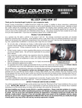
b) Use the appropriate socket to undo the lug nuts and remove the
wheels. (PHOTO 1)
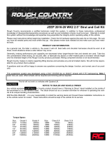
c) Remove the sway bar from the vehicle completely by disconnecting it
from the end link using a 15m wrench & socket, and removing the
brackets using a 10mm socket. (PHOTO 2)
d) Using a 21mm wrench, remove the tie-rod nut. Strike the side of the
mount with a dead blow hammer to dislodge the tie rod end. A 10mm
wrench may be needed if the ball joint is spinning. (PHOTO 3)
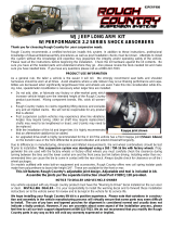
e) Using a 10mm wrench and panel poppers, remove all mounting points
for the brake line including the bracket on the knuckle and abs sensor
wire from the control arm and spindle. Undo the brake caliper mounting
bolts located at the back of the assembly with an 18mm socket and re-
move them, hang the calipers to prevent stretching of the lines using
large zip ties or hangers. Remove the rotors by removing the T30 Torx
screw and put it to the side. (PHOTO 4)
1
4
2
3
150201-888 10/09/2019 6
A Division of KW AUTOMOTIVE North America, Inc.
2) FRONT INSTALL INSTRUCTIONS CONTINUED
f. Remove and unplug the ABS sensor wire from the spindle.
Use a 5mm allen for the ABS Sensor. (PHOTO 5)
g. Remove the axle nut located underneath the dust cap using a
36mm socket. This will help prevent the axle from pulling out
of the differential and causing damage. (PHOTO 6)
h. Support the spindle by gently lifting against it with a jack. This
is to prevent the spindle assembly from falling during the next
two steps.
i. Loosen the upper ball joint nut using a 19mm wrench. Strike
the spindle on the designated bosses to help separate the
upper control arm from the spindle. Remove Nut. Be careful,
the upper control arm could be under tension. Allow the spin-
dle to droop as you slide the axle shaft out of the hub.
(PHOTO 7)
j. Remove the lower ball joint nut using a 24mm wrench and
strike it on the designated bosses to separate from the lower
control arm. Be sure to hold the spindle as it breaks free to
prevent damage. (PHOTO 8)
k. Uninstall the strut. The top nuts can be removed with an
18mm wrench. Remove the hardware holding the bottom of
the strut to the control arm using a 15mm socket and remove
the strut from the vehicle. (PHOTO 9)
l. Remove the CV axle by removing the 6 bolts attaching it to
the front differential using a 15mm socket. (PHOTO 10)
6
7
7
8
9
6
5
10
150201-888 10/09/2019 7
A Division of KW AUTOMOTIVE North America, Inc.
2) FRONT INSTALL INSTRUCTIONS CONTINUED
m. Remove the lower control arms from the frame using an 18 &
24mm socket. A breaker bar may be required. (PHOTO 11)
n. Remove the OEM equipped plastic gravel guards.
o. Disconnect the three electrical connections of the differential,
rubber vent hose and disconnect the driveshaft from the differ-
ential (PHOTO 12)
p. Remove the 4 bolts and nuts holding the crossmember under-
neath the differential, and remove the crossmember. (PHOTO
13)
q. Reference photo 16 for the next step. Measure 3/4” from the
edge of hole A, and mark a vertical line to cut the area of the
crossmember that will interfere with the differential. Only do
this on the driver side. (PHOTO 14 & 15)
r. It is recommended that you remove the differential completely
before continuing on with the procedures. Regardless of pro-
cedure, ensure the differential is always supported.
s. Install the differential drop spacers to the frame using OEM
hardware. Both diff drops should have the tapered end toward
the rear of the vehicle and the flat faces facing inward.
t. Raise and install the differential, reconnect driveshaft and
electrical connections. The differential attaches to the drops
using the supplied M14 hardware found within the 150201D-
777 packet.
15
CUT HERE
11
14
13
12
HOLE A
150201-888 10/09/2019 8
A Division of KW AUTOMOTIVE North America, Inc.
3) FRONT INSTALL CONTINUED
w. Install the front and rear crossmembers using OEM hardware and
torque to 130 ft-lb. (PHOTO 16 &17)
x. Install the OEM lower control arms into the front and rear cross-
members using the supplied M16 Bolts found within the 150201A-
777 packet. . Install the Lower A frame support rods. They will
connect between the front and rear crossmembers and attach us-
ing the same hardware as the lower control arms. (PHOTO 18)
y. Install the CV axles with the spacers between the mounting hub
and the differential mounting plate. Use the 12 supplied extended
CV axle bolts found within the 150201B-777 hardware packet.
z. Install the new sway bar by the frame mounts. Use the supplied
bushing hardware and OEM bolts. Refer to the provided instructs
for additional information.
aa. Refer to the supplied 28004 instructions for strut assembly, de-
sired height and ring position. Use the supplied M10 hardware
found in 150201C-777 packet to mount the lower bushing to OEM
control arm. (PHOTO 19)
bb. Remove the tie rod end and replace with the supplied tie rod end.
(PHOTO 20)
cc. Remove the hub and brake backing plate from the factory spindle.
Install on the lift spindle. (PHOTO 21)
dd. Install the assembled lift spindle in the reverse order of the dein-
stallation, making sure the axle shaft does not pull out of its
mounting point on the differential. Tighten the axle nut to 180ft-lbs.
ee. Torque the upper and lower ball joints to 85 ft-lbs.
16
17
20
22
20
18
21
LOWER A FRAME
SUPPORT RODS
19
150201-888 10/09/2019 9
A Division of KW AUTOMOTIVE North America, Inc.
2) FRONT INSTALL INSTRUCTIONS CONTINUED
gg. Reinstall the ABS harness, sensor, rotor and brake calipers
using the OEM hardware in reverse process of deinstalla-
tion.
hh. install the outer tie rod to the spindle using the supplied
hardware. Torque to 65 ft-lbs. (PHOTO 22)
ii. Remove the brake line brackets by the top of the strut tower
and install the brake line relocation brackets
jj. Reconnect the sway bar end links back to the lower control
arm and sway bar using factory hardware. Torque to 35 ft-
lbs. (PHOTO 23)
kk. Install the skid plate using the supplied M12 hardware within
he 150201F-777 kit and torque to 50 ft-lbs on the front
crossmember, 30 ft-lbs on the rear crossmember. (PHOTO
24)
ll. Using a 21mm socket remove the two nuts holding the
crossmember located towards the center of the vehicle and
install the rear compression arm bracket. The crossmember
does not get removed so removing the bolts is not neces-
sary. Factory hardware is retained. Also mount the front
compression arm brackets to the rear crossmember using
the supplied hardware within the 150201E-777 packet..
(PHOTO 25)
mm.Assemble the compression arms by pushing the supplied
bushings into each end and pressing in the center tube
found in 150201-100-HW bag . Once assembled mount the
compression arms into the brackets and using the remaining
hardware supplied in the 150201E-777. Swing the front of
the compression arms up and attach them to the rear cross-
member in similar manner to the rear of the arms. Torque to
100 ft-lbs. (PHOTO 26)
nn. Mount the brake line to the upper control arm as shown us-
ing the front brake line relocation bracket and the supplied
bolt within the 150201H-777 packet.
oo. Install wheel spacers only if retaining stock wheels, or keep
with truck for installing the spare. Install the wheels.
pp. Lower the front of the vehicle to the ground. The front instal-
lation is complete. Check that all hardware is torqued and
installed properly.
11
23
24
25
24
22
26
150201-888 10/09/2019 10
A Division of KW AUTOMOTIVE North America, Inc.
3) Rear Lift Installation
a) If not using a hoist, chock the front wheels to prevent the vehi-
cle from moving while the rear end is lifted.
b) Jack up the rear of the vehicle from the differential.
c) Place jack stands under the frame rails and lower the vehicle
onto the jack stands carefully.
d) Remove the wheels.
e) Remove the factory shock absorbers using a 21mm wrench &
socket. The factory hardware will be reused. (PHOTO 27)
f) Remove the factory u-bolts and carrier plates by evenly undo-
ing the nuts using a 21mm socket, then remove the factory
blocks. Slowly lower the axle to allow for the new lift block to
be installed. (PHOTO 28)
g) Install the block on the factory spring pad with the flat part of
the block on the spring and the tapered end towards the
front. Jack up the axle to meet the springs, making sure to
align the center pin. (PHOTO 29)
h) With the floor jack applying slight pressure to the rear axle to
keep the pin aligned, install the new supplied u-bolt hardware
found within the 150201G-777 packet and tighten in a cross-
ing pattern.
i) Locate the new shock absorbers, and install the shock ab-
sorbers in the factory mounting locations using the factory
hardware. Tighten using a 21mm wrench & socket. (PHOTO
30)
j) Reattach the brake lines and harness wherever they were un-
done from their factory locations to create slack. Ensure that
once reinstalled, none of the brake lines are being stretched
before continuing.
k) Install the tires/wheels.
l) Jack up the vehicle to remove the jack stands. Remove the
jack stands and lower the vehicle to the ground.
m) The rear installation is now complete.
27
28
29
30
150201-888 10/09/2019 11
A Division of KW AUTOMOTIVE North America, Inc.
4) Post Install
a) Check that all components and fasteners have been properly installed, tightened and torqued.
b) Check brake hoses, and other components for any possible interference.
c) Torque lug nuts to OEM ( factory) specifications.
d) Test drive the vehicle in a remote location so that you can become accustomed to the altered
driving characteristics and handling. Be aware that the vehicle will handle substantially different
now that it has been modified.
e) We recommend the vehicle be taken to a qualified wheel alignment facility to be realigned to
factory specifications after completing the install.
f) Installation is complete. Check ALL of the hardware and re-torque at intervals for the first 10,
100, 1000 miles.
  • Page 1 1
  • Page 2 2
  • Page 3 3
  • Page 4 4
  • Page 5 5
  • Page 6 6
  • Page 7 7
  • Page 8 8
  • Page 9 9
  • Page 10 10
  • Page 11 11

Belltech 150203HK Installation guide

Type
Installation guide

Belltech 150203HK is a 7-inch lift kit designed to improve the performance of your 2015-2018 GM 1500 pickup truck. With this kit installed, you can expect better off-road capabilities, increased ground clearance, and a more aggressive stance. The kit includes all the necessary components for a complete installation, including crossmembers, spindles, CV axle spacers, tie rod ends, space wheel spacers, lifting struts, differential drop kits, compression arms, brackets, and a skid plate.

Ask a question and I''ll find the answer in the document

Finding information in a document is now easier with AI