
2017/09 F.2 6506-209-001 REV F www.stryker.com
Operations Manual
Power-PRO™ XT
6506

sample text

www.stryker.com 6506-209-001 REV F
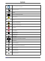
Symbols
Refer to instruction manual/booklet
Operating instructions
CE mark
European authorized representative
General warning
Caution
Warning; crushing of hands
Warning; non-ionizing radiation
No pushing
Do not lubricate
Catalogue number
Lot (batch) code
Serial number
For US Patents see www.stryker.com/patents
Manufacturer
Date of manufacture
Mass of equipment with safe working load
Safe working load
Type B applied part
Type BF applied part

6506-209-001 REV F www.stryker.com
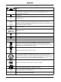
Symbols
Lift here
Medical Equipment Classified by Underwriters Laboratories Inc. With Respect to Electric Shock,
Fire, and Mechanical Hazards Only in Accordance with ANSI/AAMI ES60601-1:2012 and
CAN/CSA-C22.2 No. 60601-1:14.
Direct current
~
Alternating current
Class II electrical equipment: equipment in which protection against electric shock does not
rely on basic insulation only, but in which additional safety precautions such as double
insulation or reinforced insulation are provided, there being no provision for protective earthing
or reliance upon installation conditions.
Dangerous voltage
SMRT power system
Extend
Retract
IPX0 Non-protected
IPX6 Protection from powerful water jets
In accordance with European Directive 2002/96/EC on Waste Electrical and Electronic
Equipment, this symbol indicates that the product must not be disposed of as unsorted
municipal waste, but should be collected separately. Refer to your local distributor for return
and/or collection systems available in your country.
Cd
WEEE Directive (2012/96/EC). Contains cadmium.
The Rechargeable Battery Recycling Corporation (RBRC) is a non-profit, public service
organization that promotes the recycling of portable rechargeable batteries. Batteries must be
delivered to a battery collection site. Visit the RBRC website (www.rbrc.org) to find a nearby
collection site or call the phone number shown on the recycling symbol.
Contains nickel cadmium cells and should be recycled accordingly
DATA _+
Battery terminal identification (data line, negative, and positive)
KRX
23/44 Ni-Cd cell identification per IEC 61951-1:20 03
2300 mAh
(1.2A/2h) Battery capacity, typical charge, and duration

www.stryker.com 6506-209-001 REV F
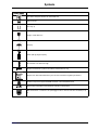
Symbols
< 60s > 300s
Cot duty cycle: 16.7% (less than 60 seconds on, more than 300 seconds off)
This device complies with Part 18 of the FCC rules
Two person lift
This way up
Fragile, handle with care
Keep dry
450 lb /205 kg weight capacity
3
Do not stack more than three high
U.S.A.
English text below this symbol is intended for USA audiences only
TRA
Registered No:
ER35122/14
Dealer No:
DA35173/14
Registered in United Arab Emirates by the Telecommunications Regulatory Authorities
Product complies with applicable EMC standards in Australia/New Zealand
50
Approved by independent communications authority of South Africa
Box manufacturer’s certificate - this packaging box has a minimum test value of 500 lb per sq.
in

sample text

www.stryker.com 6506-209-001 REV F 1
Table of Contents
Warning/Caution/Note Definition...................................................................................................................4
Summary of safety precautions....................................................................................................................5
Pinch points .......................................................................................................................................8
Mechanical stability .............................................................................................................................9
Introduction............................................................................................................................................ 11
Product description............................................................................................................................ 11
Indications for use ............................................................................................................................. 11
Expected service life .......................................................................................................................... 12
Contraindications............................................................................................................................... 12
Specifications - Power-PRO................................................................................................................. 12
Standards with required options............................................................................................................ 14
Specifications - SMRT........................................................................................................................ 15
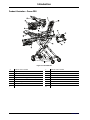
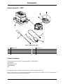
Product illustration - Power-PRO........................................................................................................... 16
Product illustration - SMRT .................................................................................................................. 17
Contact information............................................................................................................................ 17
Serial number location - Power-PRO...................................................................................................... 18
Serial number location - SMRT............................................................................................................. 18
Date of manufacture .......................................................................................................................... 18
Setup.................................................................................................................................................... 19
Installation ............................................................................................................................................. 20
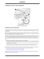
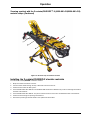
Installing the cot fastener .................................................................................................................... 20
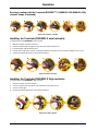
Installing the in-fastener shut-off........................................................................................................... 20
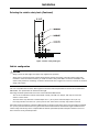
Selecting the vehicle safety hook.......................................................................................................... 21
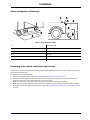
Vehicle configuration.......................................................................................................................... 22
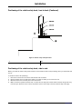
Positioning of the vehicle safety hook, front to back .................................................................................. 23
Positioning of the vehicle safety hook, side to side.................................................................................... 24
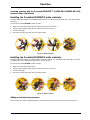
Installing the vehicle safety hook........................................................................................................... 25
Operation .............................................................................................................................................. 27
Setting cot load height with jog function.................................................................................................. 27
Checking the battery power level .......................................................................................................... 27
Checking the hour meter and error display..............................................................................................28
Operating guidelines .......................................................................................................................... 29
Proper lifting techniques ..................................................................................................................... 29
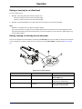
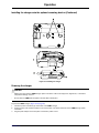
Transferring the patient to the cot .........................................................................................................30
Rolling the cot with a patient ................................................................................................................ 30
Raising or lowering the cot................................................................................................................... 30
Raising, lowering, or releasing the cot with power ..................................................................................... 31
Raising or lowering the cot manually with the manual override ..................................................................... 31
Expediting load with the high speed retract mode ..................................................................................... 32
Loading or unloading a cot with the Power-LOAD option............................................................................. 32
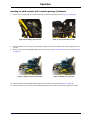
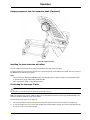
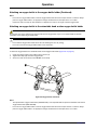
Loading a cot into a vehicle with an antler style cot fastener ....................................................................... 33
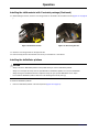
Unloading a cot from a vehicle with an antler style cot fastener ................................................................... 34
Positioning operators and helpers ......................................................................................................... 36

2 6506-209-001 REV F www.stryker.com
Table of Contents
Raising or lowering the backrest ........................................................................................................... 37
Raising or lowering the siderails............................................................................................................ 37
Raising or lowering the siderails (XPS option) .......................................................................................... 37
Extending the retractable head section................................................................................................... 38
Retracting the retractable head section.................................................................................................. 38
Raising or lowering the footrest............................................................................................................. 39
Raising or lowering the optional knee gatch............................................................................................. 39
Applying or releasing a wheel lock......................................................................................................... 40
Applying or releasing the optional Steer-LOCK ......................................................................................... 40
Applying or releasing the optional kickstand for dialysis scale...................................................................... 40
Securing the patient with the G-rated restraint straps................................................................................. 41
Adjusting restraint straps..................................................................................................................... 43
Securing a patient with the X-restraint/RUGGED™-X (6500-001-430/6506-001-430) restraint straps .................. 44
Adding a restraint strap extension ......................................................................................................... 47
Securing the patient with the Pedi-Mate® infant restraint system ................................................................. 48
Installing the child restraint with X-restraint package.................................................................................. 48
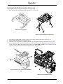
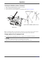
Installing the defibrillator platform.......................................................................................................... 50
Hanging equipment from the equipment hook .......................................................................................... 52
Installing the head extension with pillow.................................................................................................. 53
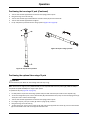
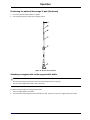
Positioning the two-stage IV pole........................................................................................................... 53
Positioning the optional three-stage IV pole ............................................................................................. 54
Attaching an oxygen bottle to the oxygen bottle holder............................................................................... 55
Attaching an oxygen bottle to the retractable head section oxygen bottle holder.............................................. 56
Installing the optional base storage net................................................................................................... 57
Installing the backrest storage pouch..................................................................................................... 57
Installing the optional head end storage flat ............................................................................................. 58
Transferring larger patients.................................................................................................................. 59
Attaching the mattress........................................................................................................................ 59
Installing a SMRT Pak ........................................................................................................................ 60
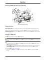
Removing a SMRT Pak from the cot ...................................................................................................... 60
Storing the battery ............................................................................................................................. 61
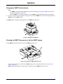
Charging the SMRT Pak...................................................................................................................... 61
Checking the SMRT Pak power level with the SMRT charger ...................................................................... 62
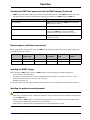
Electrical power installation requirements ............................................................................................... 63
Installing the SMRT charger................................................................................................................. 63
Installing the optional mounting bracket .................................................................................................. 63
Installing the charger onto the optional mounting bracket ........................................................................... 64
Powering the charger ......................................................................................................................... 65
Disconnecting the charger................................................................................................................... 66
Accessories ........................................................................................................................................... 67
Cleaning................................................................................................................................................ 68
Suggested cleaners........................................................................................................................... 68
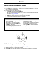
Cleaning the charger.......................................................................................................................... 69

www.stryker.com 6506-209-001 REV F 3
Table of Contents
Cleaning the battery........................................................................................................................... 69
Preventive maintenance............................................................................................................................ 71
Lubrication....................................................................................................................................... 71
Regular inspection and adjustments ...................................................................................................... 71
Foot end fastener part replacement schedule.......................................................................................... 74
EMC information ..................................................................................................................................... 75
Warranty ............................................................................................................................................... 79
Warranty exclusion and damage limitations............................................................................................. 79
To obtain parts and service.................................................................................................................. 80
Return authorization........................................................................................................................... 80
Damaged product.............................................................................................................................. 80
International warranty clause ............................................................................................................... 80

4 6506-209-001 REV F www.stryker.com
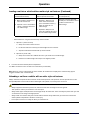
Warning/Caution/Note Definition
The words WARNING,CAUTION , and NOTE carry special meanings and should be carefully reviewed.
WARNING
Alerts the reader about a situation which, if not avoided, could result in death or serious injury. It may also describe
potential serious adverse reactions and safety hazards.
CAUTION
Alerts the reader of a potentially hazardous situation which, if not avoided, may result in minor or moderate injury to the
user or patient or damage to the product or other property. This includes special care necessary for the safe and
effective use of the device and the care necessary to avoid damage to a device that may occur as a result of use or
misuse.
Note: Provides special information to make maintenance easier or important instructions clearer.

www.stryker.com 6506-209-001 REV F 5
Summary of safety precautions
Always read and strictly follow the warnings and cautions listed on this page. Service only by qualified personnel.
WARNING
• Always keep your hands clear of the red safety bar pivots when you load, unload, or change the height position of
the cot.
• Always use both hands when you transport the cot.
•Power-PRO with the Power-LOAD compatibility option operates primarily at these frequencies: 70 - 85 kHz for
inductive charging and 13.56 MHz±7 kHz, Amplitude Modulated (OOK), ERP: -82.37 dBm. The inductive charging
can operate between these frequencies: 70 - 125 kHz. Other equipment may interfere with the Power-LOAD system,
even if that other equipment complies with CISPR emission requirements.
• Always install the in-fastener shut-off system in any emergency vehicle that will be used with this cot if using an
antler style cot fastener.
• Install the cot fastener by qualified personnel only. Improper installation could result in injury to the patient or
operator.
• Always make sure that all cots meet the installation specifications for the Stryker cot fastener system.
• Always position the in-fastener shut-off before you place the cot into service.
• Do not attempt to operate the cot when it is loaded into a cot fastener.
• Always use the in-fastener shut-off to disable the electronic functionality only. Do not use the in-fastener shut-off for
any other purpose.
• Do not remove the battery when the cot is active.
• Always operate the cot only when all persons are clear of the mechanisms. Entanglement in powered cot
mechanisms can cause serious injury.
• Always inspect SMRT Paks for damage before every use.
• Do not allow untrained assistants to assist in the operation of the product.
• Do not ride on the base of the cot.
• Do not transport the cot sideways to avoid the risk of tipping. Always transport the cot in a lowered position, head end
or foot end first to minimize the risk of tipping.
• Always conduct patient monitoring when the cot is idle. If you hydraulically raise or lower the product you may
temporarily affect electronic patient monitoring equipment.
• Do not leave a patient unattended. Hold the product while a patient is on the product.
• Do not apply a wheel lock when a patient is on the product or when you move the product to avoid the risk of tipping.
• Do not use siderails as a patient restraint device.
• Always transport the cot at a lower height to reduce the risk of a cot tip. If possible, obtain additional assistance or
take an alternate route.
• Always avoid high obstacles, such as curbing, steps, or rough terrain to avoid the risk of the product tipping over.
• Always use Power-LOAD with the 6085/6086 Performance-PRO XT, 6500/6506 Power-PRO XT, and 6510/6516
Power-PRO IT cots with the Power-LOAD option only. In certain situations, you can use Power-LOAD as a standard
antler for most X-frame cots, but a rail clamp assembly is required for all cots without the Power-LOAD option.
• Always make sure that you use a Power-LOAD date of manufacture cot with the Stryker Model 6390 Power-LOAD
system to avoid the risk of injury.
• Always support the load of the patient, cot, and accessories after the weight is off of the ground.
• Do not pull or lift on the cot safety bar when you unload the cot.
• Always lock the head section into place before you operate the cot.
• Do not load the cot into a vehicle with the head section retracted when using a cot fastener. The cot may tip or not
connect with the cot fastener.
• Do not install or apply a wheel lock on a product with worn wheels that are less than 6 in. diameter.

6 6506-209-001 REV F www.stryker.com
Summary of safety precautions
WARNING (CONTINUED)
• Always use two people when using the kickstand.
• Always center the patient weight on the cot before you use the kickstand.
• Always apply the kickstand with your foot only.
• Always lower the cot height before you apply the kickstand for increased stability.
• Do not apply the kickstand during transport. Keep the kickstand in the retracted position.
• Do not use the kickstand as a brake.
• Do not apply the kickstand on a sloped surface.
• Always use all restraint straps to secure the patient on the cot. An unrestrained patient may fall from the cot.
• Do not attach restraint straps to the base tubes or cross tubes.
• Always use all restraint straps to secure the patient on the cot. An unrestrained patient may fall from the cot.
• Do not attach restraint straps to the base tubes or cross tubes.
• Always locate the buckle away from obstructions or accessories on the cot to avoid the risk of accidental release of
Pedi-Mate®infant restraint system and injury to the infant.
• Do not pinch your fingers between the fowler bracket and the oxygen bottle if your cot is equipped with the optional
retractable head section oxygen bottle holder.
• Do not remove the battery when the cot is activated.
• Do not attempt to open the battery pack for any reason, to avoid the risk of electric shock. If the battery pack case is
cracked or damaged, do not insert it into the charger. Return damaged battery packs to a service center for
recycling.
• Always avoid direct contact with a wet battery or battery enclosures. Contact may cause injury to the patient or
operator.
• Do not insert a cracked or damaged SMRT Pak into the SMRT charger. Return damaged SMRT Paks to a service
center for recycling.
• Always have a certified mechanic, familiar with ambulance vehicle construction, install the optional mounting bracket
and the SMRT charger.
• Always mount the SMRT charger to the optional mounting bracket in an enclosed cabinet and out of patient reach
during transport to comply with established crash test standards.
• Always make sure that the optional mounting bracket is securely attached to the surface.
• Always use any appropriate personal protective equipment while power washing to avoid inhaling contagion. Power
washing equipment may aerate contamination.
• Always wipe the product with clean water and dry after cleaning. Some cleaning products are corrosive in nature and
may cause damage to the product. Failure to properly rinse and dry the product leaves a corrosive residue on the
surface of the product and may cause premature corrosion of critical components.
• Always wear insulated rubber gloves, in addition to personal protective equipment, when cleaning the SMRT Pak to
reduce the risk of injury.
• Always disconnect the SMRT charger from the wall outlet before cleaning to avoid the risk of electrical hazards.
• Do not spray fluid directly onto the SMRT charger.
• Do not power wash the SMRT charger.
• Do not immerse the SMRT charger in water or allow water to collect on top of the SMRT charger to avoid the risk of
electric shock.
• Always use only non-conductive materials to wipe the SMRT Pak.
• Always refer to the disinfectant’s Material Safety Data Sheet (MSDS) to verify the pH range. Disinfectants with pH
levels higher than 10.5 may cause the SMRT Pak housing material to crack.

www.stryker.com 6506-209-001 REV F 7
Summary of safety precautions
WARNING (CONTINUED)
• Do not directly handle or make contact with the SMRT Pak terminals while cleaning to avoid the risk of injury.
• Do not immerse the SMRT Pak in liquid to reduce the risk of electric shock.
• Do not use solvents, lubricants, or other chemicals to clean the SMRT Pak unless otherwise directed.
• Always relieve pressure before you disconnect hydraulic or other lines. Escaping fluid under pressure can penetrate
the skin and cause serious injury. Tighten all connections before you apply pressure. If an accident occurs, see a
doctor immediately.
• Do not use bare hands to check for hydraulic leaks.
CAUTION
• Improper usage of the product can cause injury to the patient or operator. Operate the product only as described in
this manual.
• Do not modify the product or any components of the product. Modifying the product can cause unpredictable
operation resulting in injury to patient or operator. Modifying the product also voids its warranty.
• This equipment has been tested and found to comply with the limits for a Class A digital device, pursuant to part 15
of the FCC Rules. These limits are designed to provide reasonable protection against harmful interference when the
equipment is operated in a commercial environment. This equipment generates, uses, and can radiate radio
frequency energy and, if not installed and used in accordance with the instruction manual, may cause harmful
interference to radio communications. Operation of this equipment in a residential area is likely to cause harmful
interference in which case the user will be required to correct the interference at their expense.
• Always set the cot load height to the proper stop height before operation.
• Always have a certified mechanic, familiar with ambulance vehicle construction, install the vehicle safety hook.
Consult the vehicle manufacturer before you install the vehicle safety hook. Make sure that the installation of the
vehicle safety hook does not damage or interfere with the brake lines, oxygen lines, fuel lines, fuel tank, or electrical
wiring of the vehicle.
• Always charge the battery before you place the product into service. An uncharged or depleted battery may cause
poor product performance.
• Always clear any obstacles that may interfere and cause injury to the operator or patient before operating the
product.
• Do not entangle the restraint straps in the base frame when you raise or lower the cot.
• Always secure the defibrillator platform to the product when you use the defibrillator platform.
• Always use and adjust the straps that are provided with the defibrillator platform to secure the defibrillator.
• Always change the installation location or adjust the straps for your specific defibrillator size or shape.
• Do not load the defibrillator platform above the safe working load of 30 lb (13.6 kg).
• Do not load the equipment hook above the safe working load of 35 lb (15.8 kg).
• Always remove all accessories or equipment from the equipment hook when in the vehicle.
• Do not load the oxygen bottle holder above the safe working load of 15 lb (6.8 kg).
• Do not use two oxygen bottle holders at the same time.
• Do not load the backrest storage pouch above the safe working load of 20 lb (9 kg).
• Do not allow the storage pouch to interfere with the operation of the retractable head section.
• Always remove the battery if the cot is not going to be used for an extended period of time (more than 24 hours).
• Always place the electrical SMRT charger power cord where it will not be stepped on, tripped over, or otherwise
subjected to damage or stress.
• Do not touch the SMRT Pak receptacle terminals with metal objects.

8 6506-209-001 REV F www.stryker.com
Summary of safety precautions
CAUTION (CONTINUED)
• Always grasp and pull the plug, not the cord, when you disconnect the SMRT charger to avoid the risk of damage to
the electrical plug and cord.
• Do not steam clean or ultrasonically clean the product.
• Do not exceed 180 °F (82 °C) as the maximum water temperature.
• Do not exceed 1500 psi (130.5 bar) as the maximum water pressure. If you are using a hand held wand to wash the
product, keep the pressure nozzle at a minimum of 24 in. (61 cm) from the product.
• Always allow to air dry.
• Always remove the battery before you wash the cot.
• Do not clean, service, or perform maintenance while the product is in use.
• Do not steam clean or ultrasonically clean the SMRT Pak.
• Always use authorized parts to avoid the risk of product damage.
• Always check hoses and lines regularly to avoid damage to the cot. Check and tighten loose connections. Hydraulic
lines, hoses, and connections can fail or loosen due to physical damage, kinks, age, and environment exposure.
• Do not tip the cot onto its load wheels and actuate the product as this will allow air to enter the hydraulic system.
• The use of accessories, transducers, and cables, other than those specified or provided by the manufacturer, could
result in increased electromagnetic emissions or decreased electromagnetic immunity and result in improper
operation.
• The emissions characteristics of this equipment make it suitable for use in industrial areas and hospitals (CISPR 11
class A). If it is used in a residential environment, for which CISPR 11 class B is normally required, this equipment
might not offer adequate protection to radio frequency communication services. The user might need to take
mitigation measures, such as relocating or reorienting the equipment.
• Avoid stacking or placing other equipment adjacent to Power-PRO and SMRT charger to prevent improper operation
of the products. If such use is necessary, carefully observe Power-PRO and SMRT charger and the other equipment
to make sure that they are operating properly.
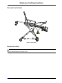
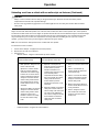
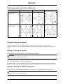
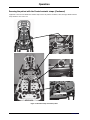
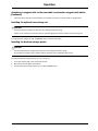
Pinch points
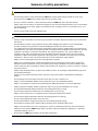
WARNING
Always keep your hands clear of the red safety bar pivots when you load, unload, or change the height position of the cot.

www.stryker.com 6506-209-001 REV F 9
Summary of safety precautions
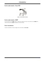
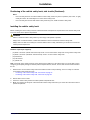
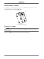
Pinch points (Continued)
Figure 1: Pinch points
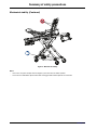
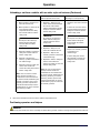
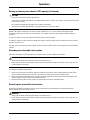
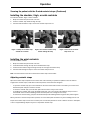
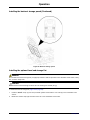
Mechanical stability
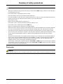
WARNING
Always use both hands when you transport the cot.

10 6506-209-001 REV F www.stryker.com
Summary of safety precautions
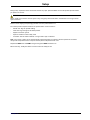
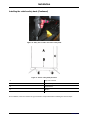
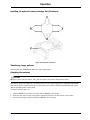
Mechanical stability (Continued)
Figure 2: Mechanical stability
Notes
• If the cot is on a plane steeper than five degrees, place the cot in the lowest position.
• Do not use the defibrillator option and the foot end oxygen bottle holder option at the same time.

www.stryker.com 6506-209-001 REV F 11
Introduction
This manual assists you with the operation or maintenance of your Stryker product. Read this manual before operating or
maintaining this product. Set methods and procedures to educate and train your staff on the safe operation or
maintenance of this product.
CAUTION
• Improper usage of the product can cause injury to the patient or operator. Operate the product only as described in
this manual.
• Do not modify the product or any components of the product. Modifying the product can cause unpredictable
operation resulting in injury to patient or operator. Modifying the product also voids its warranty.
Notes
• This manual is a permanent part of the product and should remain with the product even if the product is sold.
• Stryker continually seeks advancements in product design and quality. This manual contains the most current
product information available at the time of printing. There may be minor discrepancies between your product and
this manual. If you have any questions, contact Stryker Customer Service or Technical Support at 1-800-327-0770.
Product description
The Stryker Model 6506 Power-PRO™XT cot is a powered ambulance cot that consists of a platform mounted on a
wheeled X-frame designed to support and transport a maximum weight of 700 lb (318 kg) in pre-hospital and hospital
environments.
The device is collapsible for use in emergency vehicles and has an adjustable load height feature to allow the device to
be set to different ambulance deck heights for proper body mechanics during loading and unloading. The NiCd battery-
powered hydraulic lift system allows operators to raise and lower the cot using the powered controls, while duplicate foot-
end controls on the upper and lower lift bars accommodate different operator positions or sizes. The cot is equipped with
a manual back-up release handle to allow the operation of cot functions in the event of power loss. The device is
equipped with a retractable head section for 360-degree mobility in any height position, side rails, patient securement
straps, an adjustable pneumatic backrest, and various optional accessories that assist with the transport of a patient.
Maximum patient comfort is attainable with the three different litter positions of shock, flat leg, and optional knee gatch
positioning.
The SMRT™power system consists of a SMRT charger and a SMRT Pak. The SMRT Pak powers the hydraulic lift
system of the Stryker powered ambulance cots.
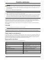
Indications for use
The Stryker Power-PRO XT is a powered wheeled stretcher, which is intended to support and transport the entire body of
a traumatized, ambulatory, or non-ambulatory human patient (includes infants and adults).
The battery-powered hydraulic lift system is intended to help reduce the effort required by the operator to raise and lower
the cot. The device is designed to support patients in a supine (horizontal) or sitting position and facilitate the
transportation of associated medical equipment (such as oxygen bottles, monitors, or pumps) in emergency or transport
vehicles. This ambulance cot is intended to be used in pre-hospital and hospital environments, and in emergency and non-
emergency applications. It is rated to a maximum capacity of 700 lb (318 kg) (sum of the patient, mattress, and
accessory weight) and the intended operators of the device are trained professionals including emergency medical
service and medical care center personnel, as well as medical first responders.
Power-PRO XT is not intended for extended stay or use as a hospital bed or in devices that modify air pressure, such as
hyperbaric chambers.

12 6506-209-001 REV F www.stryker.com
Introduction
Expected service life
Power-PRO has a seven year expected service life under normal use conditions and with appropriate periodic
maintenance.
The SMRT charger has a seven year expected service life under normal use conditions and with appropriate periodic
maintenance.
The SMRT Pak battery has a two year expected service life under normal use conditions.
Contraindications
None known.
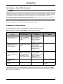
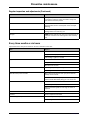
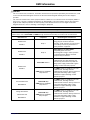
Specifications - Power-PRO
Safe working load
Note: Safe working load indicates
the sum of the patient, mattress,
and accessory weight.
700 lb 318 kg
Maximum unassisted lift capacity 1500 lb 227 kg
Backrest articulation/shock position (standard fowler -
6506-012-003)
0° to 73°/+15°
Backrest articulation/shock position (1865 fowler
option - 6506-012-004)
0° to 75°/+15°
Backrest articulation/shock position (6506-700-013) 6° to 73°/+15°
Overall length/minimum length/width 81 in./63 in./23 in. 206 cm/160 cm/58 cm
Height 2Adjustable from 14 in. to
41.5 in.
Adjustable from 36 cm to
105 cm
Weight 3125 lb 57 kg
Caster diameter/width 6 in./2 in. 15 cm/5 cm
Minimum operators required for loading/ unloading an
occupied cot
2
Minimum operators required for loading/ unloading an
unoccupied cot
1
Recommended fastener systems Model 6370 or 6377 Floor mount type, Model 6371 Wall
mount type, Model 6390 Power-LOAD, Model 6392
Performance-LOAD
Recommended loading height 4Up to 36 in. Up to 91 cm
Recommended working height (excluding mattress) 15.75 in. 40 cm
Hydraulic oil Stryker part number 6500-001-293
Power system
Battery 24 VDC NiCd - SMRT power system

www.stryker.com 6506-209-001 REV F 13
Introduction
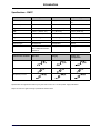
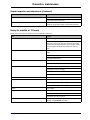
Specifications - Power-PRO (Continued)
Charger 100-240 VAC 1.20 A,
50/60 Hz or 12 VAC 4.16 A - SMRT power system
Cot duty cycle 16.7% (less than 60 seconds on, more than 300 seconds
off)
Standards (cots and chargers) ANSI/AAMI ES60601-1: 2012, CAN/CSA-C22.2 No. 60601-
1:14, KKK-A-1822
For standards that require specific options, see
Standards with required options on page 14.
1Cot loads over 300 lb (136 kg) may require additional assistance to meet the set cot load height.
2Height measured from bottom of mattress at seat section to ground level.
3Cot is weighed with one battery and without mattress and restraints.
4Set the cot height to any ambulance deck height that ranges from 26 in. to 36 in. (66 cm to 91 cm).
Stryker reserves the right to change specifications without notice.
Power-PRO XT is designed to conform to the Federal Specification for the Star-of-Life Ambulance (KKK-A-1822 ).
Power-PRO XT is designed to be compatible with some competitive cot fastener systems.
The yellow and black color scheme is a proprietary trademark of Stryker Corporation.
Hereby, Stryker declares that the radio equipment type short range device is in compliance with Directive 2014/53/EU.
The full text of the EU declaration of conformity is available at the following internet address: http://techweb.med.
strykercorp.com/EMS/EU%20Declaration%20of%20Conformity/index.html.
Labels may be unreadable from a viewing distance greater than 12 inches.
WARNING
Power-PRO with the Power-LOAD compatibility option operates primarily at these frequencies: 70 - 85 kHz for inductive
charging and 13.56 MHz±7 kHz, Amplitude Modulated (OOK), ERP: -82.37 dBm. The inductive charging can operate
between these frequencies: 70 - 125 kHz. Other equipment may interfere with the Power-LOAD system, even if that
other equipment complies with CISPR emission requirements.
Environmental conditions Operation Storage and transportation
Temperature
130 °F
(54 °C)
-30 °F
(-34 °C)
130 °F
(54 °C)
-30 °F
(-34 °C)
Relative humidity
93%
0%
93%
0%
Atmospheric pressure
1060 hPa
700
1060 hPa
700

14 6506-209-001 REV F www.stryker.com
Introduction
Specifications - Power-PRO (Continued)
CAUTION
This equipment has been tested and found to comply with the limits for a Class A digital device, pursuant to part 15 of the
FCC Rules. These limits are designed to provide reasonable protection against harmful interference when the equipment
is operated in a commercial environment. This equipment generates, uses, and can radiate radio frequency energy and,
if not installed and used in accordance with the instruction manual, may cause harmful interference to radio
communications. Operation of this equipment in a residential area is likely to cause harmful interference in which case
the user will be required to correct the interference at their expense.
Note: In accordance with the European REACH regulation and other environmental regulatory requirements, the 6500-
001-210 and 6500-001-211 hydraulic hoses contain dibutyl phthalate (DBP).
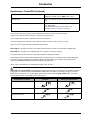
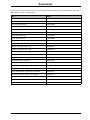
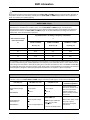
Standards with required options
To be compliant with the standards, you must install the following required options on your cot.
Note: Compatible cot is loaded into Power-LOAD in powered mode for crash testing.
Standard
Option selection
Restraint package Mattress Option
SAE J3027 crash-test
standards with the use of a
crash-rated fastener
X-restraint package (6500-
001-430) or RUGGED-X
restraint package (6506-
001-430)
Knee gatch bolster
mattress (6500-002-
150/6506-002-150 ) or XPS
mattress (6500-003-
130/6506-003-130 )
(depending on cot siderail)
AS/NZS-4535 crash-test
standards with the use of a
crash-rated fastener
X-restraint package (6500-
001-430)
Knee gatch bolster
mattress (6500-002-
150/6506-002-150 ) or XPS
mattress (6500-003-
130/6506-003-130 )
(depending on cot siderail)
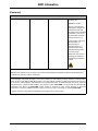
BS EN 1789:2007+A2 :2014
crash-test standards with
the use of a crash-rated
fastener
G-rated restraint package
(6500-002-030), X-restraint
package (6500-001-430),
or RUGGED-X restraint
package (6506-001-430)
Knee gatch bolster
mattress (6500-002-
150/6506-002-150 ) or XPS
mattress (6500-003-
130/6506-003-130 )
(depending on cot siderail)
BS EN 1865-3:2012
+A1:2015
XPS option (6506-040-000)
BS EN 1865-2:2010
+A1:2015
1865 fowler option (6506-
012-004)
The Britax Meridian SICT Series No. 7200/A/2010 Convertible Child Restraint with the X-restraint package (6500-001-
430) has been dynamically crash tested with a 10 kg crash dummy to 18.2 G forward and 10 G sideward per AS/NZS-
4535: 1999 crash-test standards.
Page is loading ...
Page is loading ...
Page is loading ...
Page is loading ...
Page is loading ...
Page is loading ...
Page is loading ...
Page is loading ...
Page is loading ...
Page is loading ...
Page is loading ...
Page is loading ...
Page is loading ...
Page is loading ...
Page is loading ...
Page is loading ...
Page is loading ...
Page is loading ...
Page is loading ...
Page is loading ...
Page is loading ...
Page is loading ...
Page is loading ...
Page is loading ...
Page is loading ...
Page is loading ...
Page is loading ...
Page is loading ...
Page is loading ...
Page is loading ...
Page is loading ...
Page is loading ...
Page is loading ...
Page is loading ...
Page is loading ...
Page is loading ...
Page is loading ...
Page is loading ...
Page is loading ...
Page is loading ...
Page is loading ...
Page is loading ...
Page is loading ...
Page is loading ...
Page is loading ...
Page is loading ...
Page is loading ...
Page is loading ...
Page is loading ...
Page is loading ...
Page is loading ...
Page is loading ...
Page is loading ...
Page is loading ...
Page is loading ...
Page is loading ...
Page is loading ...
Page is loading ...
Page is loading ...
Page is loading ...
Page is loading ...
Page is loading ...
Page is loading ...
Page is loading ...
Page is loading ...
Page is loading ...
Page is loading ...
-
 1
1
-
 2
2
-
 3
3
-
 4
4
-
 5
5
-
 6
6
-
 7
7
-
 8
8
-
 9
9
-
 10
10
-
 11
11
-
 12
12
-
 13
13
-
 14
14
-
 15
15
-
 16
16
-
 17
17
-
 18
18
-
 19
19
-
 20
20
-
 21
21
-
 22
22
-
 23
23
-
 24
24
-
 25
25
-
 26
26
-
 27
27
-
 28
28
-
 29
29
-
 30
30
-
 31
31
-
 32
32
-
 33
33
-
 34
34
-
 35
35
-
 36
36
-
 37
37
-
 38
38
-
 39
39
-
 40
40
-
 41
41
-
 42
42
-
 43
43
-
 44
44
-
 45
45
-
 46
46
-
 47
47
-
 48
48
-
 49
49
-
 50
50
-
 51
51
-
 52
52
-
 53
53
-
 54
54
-
 55
55
-
 56
56
-
 57
57
-
 58
58
-
 59
59
-
 60
60
-
 61
61
-
 62
62
-
 63
63
-
 64
64
-
 65
65
-
 66
66
-
 67
67
-
 68
68
-
 69
69
-
 70
70
-
 71
71
-
 72
72
-
 73
73
-
 74
74
-
 75
75
-
 76
76
-
 77
77
-
 78
78
-
 79
79
-
 80
80
-
 81
81
-
 82
82
-
 83
83
-
 84
84
-
 85
85
-
 86
86
-
 87
87


Stryker 6506 Operating instructions
- Type
- Operating instructions
- This manual is also suitable for
Ask a question and I''ll find the answer in the document
Finding information in a document is now easier with AI
Related papers
-
Stryker Power-PRO XT 6500 Operation and Maintenance Manual
-
-
-
Stryker System 9 Sterile Battery Charger Operating instructions
-
-
Stryker 1004 User manual
-
-
-
Stryker 1806 User manual
-
Other documents
-
Pulse LCD-PM200 Operating instructions
-
D ADDARIO AUTO LOCK Operating instructions
-
Arjo BOLERO Quick start guide
-
 Stryker Medical Z7A-6390 User manual
-
Community Playthings M170 User guide
-
sks VELODETECT+ User manual
-
 Prime Medical Secure360 Positioning Device Operating instructions
-
 VintageView Universal Wine Bottle Retention Straps Installation guide
-
Herman Miller Cosm Stool Product Instructions
-
 Darco 779566 Operating instructions


