14 www.stryker.com
EN 700000544314 Rev-AD
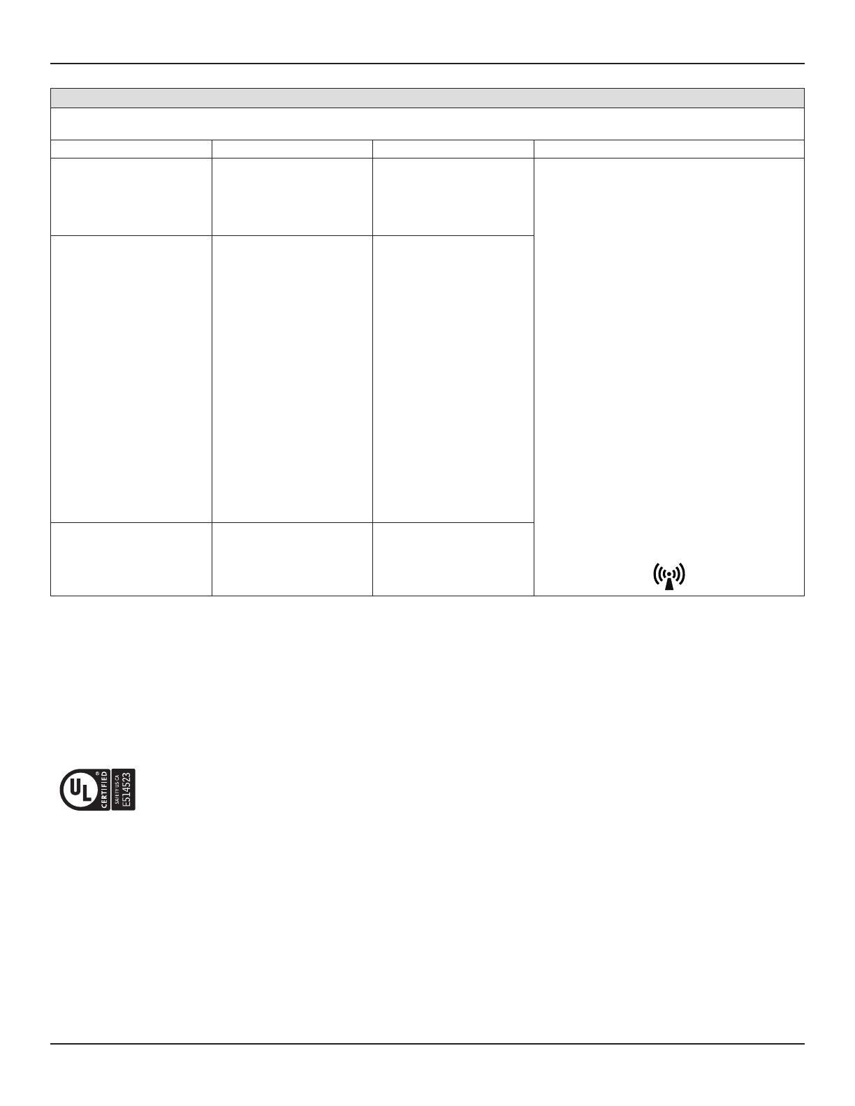
Guidance and manufacturer’s declaration - electromagnetic immunity
The System 9 Sterile Battery Charger (REF 9110-120-000) is intended for use in the electromagnetic environment specified below. The customer or the user of the
System 9 Sterile Battery Charger (REF 9110-120-000) should assure that it is used in such an environment.
Immunity test IEC 60601 test level Compliance level Electromagnetic environment - guidance
Conducted RF
IEC 61000-4-6
3 Vrms 150 kHz to 80 MHz
outside ISM bands 80% AM at
1 kHz
6 Vrms 150 kHz to 80 MHz in
ISM bands 80% AM at 1 kHz
N/A
Portable and mobile RF equipment should be used no
closer to any part of the System 9 Non- Sterile Battery
Charger (REF 9110-120-000), including cables, than the
recommended separation distance calculated from the
equation applicable to the frequency of the transmitter.
Recommended separation distance:
150 kHz to 80 MHz d=1.17√P
80 MHz to 800 MHz d=1.17√P
800 MHz to 2.7 GHz d=2.33√P
where P is the maximum output power rating of the
transmitter in watts (W) according to the transmitter
manufacturer and d is the recommended separation
distance in meters (m).
WARNING - Portable RF equipment (including peripherals
such as antenna cables and external antennas) should
be used no closer than 30 cm (12 inches) to any part
of the System 9 Sterile Battery Charger (REF 9110-120-
000), including cables specified by the manufacturer.
Otherwise, degradation of the performance of this
equipment could result.
Field strengths from fixed RF transmitters, as determined
by an electromagnetic site surveya, should be less than
the compliance level in each frequency rangeb.
Interference may occur in the vicinity of equipment
marked with the following symbol:
Radiated RF
IEC 61000-4-3
3 V/m 80 MHz to 2.5 GHz 80%
AM at 1 kHz
27 V/m 385 MHz Pulse
modulation 18 Hz, Maximum
power 1.8 W
28 V/m 450 MHz, FM ± 5 kHz
deviation, 1 kHz sine, Maximum
power 2 W
9 V/m 710, 745, 780, 5240,
5500, 5785 MHz, Pulse
modulation 217 Hz, Maximum
power 0.2 W
28 V/m 810, 870, 930 MHz, Pulse
modulation 18 Hz, Maximum
power 2 W
28 V/m 1720, 1845, 1970, 2450
MHz, Pulse modulation 217 Hz,
Maximum power 2 W
Proximity magnetic fields
IEC 61000-4-39
65 A/m 134.2 kHz, pulse
modulation 2.1 kHz
7.5 A/m 13.56 MHz, pulse
modulation 50 kHz
65 A/m 134.2 kHz, pulse
modulation 2.1 kHz
7.5 A/m 13.56 MHz, pulse
modulation 50 kHz
NOTE 1: At 80 MHz and 800 MHz the higher frequency range applies.
NOTE 2: These guidelines may not apply in all situations. Electromagnetic propagation is affected by absorption and reflection from structures, objects and people.
a Field strengths from fixed transmitters, such as base stations for radio (cellular/cordless) telephones and land mobile radios, amateur radio, AM and FM radio broadcast and TV broadcast
cannot be predicted theoretically with accuracy. To assess the electromagnetic environment due to fixed RF transmitters, an electromagnetic site survey should be considered. If the measured
field strength in the location in which the System 9 Sterile Battery Charger (REF 9110-120-000) is used exceeds the applicable RF compliance level above, the System 9 Sterile Battery
Charger (REF 9110-120-000) should be observed to verify normal operation. If abnormal performance is observed, additional measures may be necessary, such as re-orienting or relocating the
System 9 Sterile Battery Charger (REF 9110-120-000).
b Over the frequency range 150 kHz to 80 MHz, field strengths should be less than 3 V/m.
Certifications
Underwriters Laboratories Inc. certification mark for United States and Canada. These products were tested and meet medical electrical
equipment certification requirements, including compliance with applicable 60601 series standards. For additional information, contact Stryker.


