Page is loading ...

2008/11 6500-309-001 REV A www.stryker.com
Power-PRO™ XT
Model 6500
Operations/Maintenance Manual
For Parts or Technical Assistance:
USA: 1-800-327-0770 (option 2)
Canada: 1-888-233-6888


www.stryker.com 6500-309-001 REV A 3
Table of Contents
Introduction...............................................................................6
Specifications .........................................................................6
WARNING / CAUTION / NOTE DEFINITION ....................................................8
Symbols .................................................................................9
Warranty................................................................................10
Stryker EMS Return Policy ...............................................................11
Return Authorization ....................................................................11
Damaged Merchandise..................................................................11
International Warranty Clause .............................................................11
Patent Information .....................................................................11
Summary of Safety Precautions...............................................................12
Component Identification.................................................................... 17
Product Inspection ........................................................................18
General Inspection .....................................................................18
Setup Procedures .........................................................................20
Cot Load Height and “Jog” Function ........................................................21
Cot Fastener Installation ....................................................................22
In-Fastener Shut-Off....................................................................24
Vehicle Safety Hook Installation ...............................................................25
Ambulance Configuration ................................................................25
Required Hardware for Installation of the Safety Hook (Not Supplied) ................................25
Positioning and Installing the Safety Hook ....................................................26
Cot Features.............................................................................28
Using Restraint Straps ..................................................................28
Using The Restraint Belt Extension (Optional) .................................................30
Pedi-Mate™ Infant Restraint System (Optional) Attachment Instructions...............................31
Operating The Optional Wheel Lock(s) ......................................................33
Adjusting The Wheel Locking Force.........................................................34
Adjusting the Cot Retaining Post ...........................................................34
Adjusting the Footrest ...................................................................35
Operating the Backrest..................................................................36
Operating the Siderails ..................................................................36
Battery Power Indicator..................................................................37
Hour Meter ..........................................................................38
Installing the Optional Head End Storage Flat..................................................39
Installing the Optional Backrest Storage Pouch.................................................40
Using the Optional Equipment Hook ........................................................41
Operating the 2-Stage I.V. Pole (Optional Equipment) ............................................42
Operating the 3-Stage I.V. Pole (Optional Equipment) ............................................43
Cot Operation ............................................................................44
Operating Guidelines ...................................................................44
Proper Lifting Techniques ................................................................44
Transferring the Patient to the Cot..........................................................45

4 6500-309-001 REV A www.stryker.com
Table of Contents
Using the Optional Transfer Flat ...........................................................45
Ambulance Cot Motion ..................................................................45
Loading the Cot into a Vehicle with Two Operators - Powered Method ...............................46
High Speed Retract/Extend...............................................................47
Loading the Cot into a Vehicle with Two Operators at the Foot End..................................47
Loading an Empty Cot into a Vehicle with One Operator - Powered Method............................48
Unloading the Cot from a Vehicle with Two Operators - Powered Method .............................49
Unloading the Cot from a Vehicle With One Operator - Powered Method..............................50
Manual Override Operation ...............................................................51
Loading the Cot into a Vehicle with Two Operators - Manual Method ................................52
Unloading the Cot from a Vehicle with Two Operators - Manual Method..............................53
Unloading an Empty Cot from a Vehicle with One Operator - Manual Method ..........................54
Adjusting Cot Height ....................................................................55
Using Additional Assistance ..............................................................55
Operating the Retractable Head Section .....................................................56
Battery Operation......................................................................57
Cleaning................................................................................58
Washing Procedure ....................................................................58
Washing Limitations ....................................................................58
Removal of Iodine Compounds ............................................................59
Preventative Maintenance ...................................................................60
Base Lubrication ......................................................................61
Regular Inspection and Adjustments ........................................................62
Maintenance Record .......................................................................65
Training Record...........................................................................66
Cot Assembly ............................................................................67
Base Assembly...........................................................................75
Outer Lift Tube Assembly, Base Pivot - 6500-301-021 ...............................................80
Inner Lift Tube Assembly, Base Pivot - 6500-301-022 ...............................................81
Inner Lift Tube, Litter Pivot - 6500-001-034 ......................................................82
Inner Lift Tube, Litter Pivot - 6500-001-035 ......................................................83
Outer Rail, Patient Right Assembly .............................................................84
Outer Rail, Patient Left Assembly..............................................................86
Hall Sensor Assembly ......................................................................88
Sensor Housing Assembly ...................................................................89
Powerplant Assembly ......................................................................90
Hydraulic Sub-Assembly - 6500-001-030 ........................................................92
Foot End Assembly ........................................................................93
Switch Assembly - 6500-001-016 ..............................................................97
Fowler Assembly..........................................................................98
Trend Assembly ..........................................................................99
Head Section Assembly - 6500-001-020........................................................100
Cot Operation (Continued)

www.stryker.com 6500-309-001 REV A 5
Table of Contents
Head Section Lock Assembly - 6500-001-026 ...................................................102
In-Fastener Shut-Off Assembly - 6500-001-027 ..................................................103
Optional Oxygen Bottle Holder - 6500-140-000 ...................................................104
Optional Oxygen Bottle Holder Assembly - 6500-001-040 ...........................................105
Optional Head End Oxygen Bottle Holder - 6500-141-000 ...........................................106
Removable Oxygen Bottle Holder Assembly - 6080-140-010 .........................................107
Two-Stage I.V. Pole Assembly Patient Right - 6500-210-000 ..........................................108
Three-Stage I.V. Pole Assembly Patient Right - 6500-215-000......................................... 108
Three-Stage I.V. Pole Assembly Patient Right - 6500-001-043 ........................................110
Two-Stage I.V. Pole Assembly Patient Left - 6500-211-000 ..........................................111
Three-Stage I.V. Pole Assembly Patient Left - 6500-216-000 .........................................111
Two-Stage I.V. Pole Assembly Patient Left - 6500-001-042........................................... 112
Three-Stage I.V. Pole Assembly Patient Left - 6500-001-044 ......................................... 113
Two-Stage I.V. Pole Assembly, Dual - 6500-212-000 .......................................114
Three Stage I.V. Pole Assembly, Dual - 6500-217-000 .............................................. 114
Optional Defibrillator Platform - 6500-170-000.................................................... 115
Optional Head Extension - 6100-044-000 .......................................................116
Optional Head Extension Assembly - 6100-044-012 ............................................... 117
Troubleshooting Guide..................................................................... 118
Electronics and Hydraulics Locator ........................................................118
Hydraulic Manifold Components Locator ....................................................119
Electronics Assembly Wiring Schematics.................................................... 12 0
Electrical System Block Diagram ......................................................... 121
Troubleshooting Guide ................................................................. 12 3
Recycling Passport ....................................................................... 12 7
Product: 6500-700-006 ................................................................ 12 7
Product: 6500-001-016 ................................................................. 12 8
Product: 6500-001-028 ................................................................. 12 9
Product: 6500-001-015 ................................................................. 13 0
Product: 6500-001-014 ................................................................. 13 0
Product: 6500-001-030 ................................................................ 131
Product: 6500-001-159 ................................................................. 13 2
Quick Reference Replacement Part List ........................................................ 13 3
Assembly Drawings (Continued)

6 6500-309-001 REV A www.stryker.com
INTRODUCTION
This manual is designed to assist you with the operation and maintenance of the Power-PRO™ XT
Ambulance Cot. Read it thoroughly before using the equipment or beginning any maintenance on it.
SPECIFICATIONS
Maximum Cot Load Capacity 700 pounds 315 kg
Maximum Unassisted Lift Capacity 500 pounds 225 kg
Backrest Articulation/Shock Position 2° to 73° / +15°
Overall Length/Minimum Length/Width 81" / 63" / 23" 206 cm / 160 cm / 58,5 cm
Height
1
Adjustable from 14" to 41.5" 35,5 cm to 105 cm
Weight
2
122 pounds 55,3 kg
Caster Diameter/Width 6" / 2" 15,2 cm / 5,1 cm
Minimum Operators Required for Loading/
Unloading an Occupied Cot
2
Minimum Operators Required for Loading/
Unloading an Unoccupied Cot
1
Recommended Fastener Systems Model 6370 or 6377 Floor Mount Type
Model 6371 Wall Mount Type
Recommended Loading Height
3
Adjustable up to 36" 91 cm
Roll-In Style Yes
Single Wheel Lock / Double Wheel Lock Optional
Hydraulic Oil Stryker Part Number 6500-001-293
Battery System DeWALT
®
24 Volt NiCd Battery
- Battery Stryker Part Number 6500-700-006
- Charger Stryker Part Number 6500-070-000 (120 Volt)
Part Number 6500-072-000 (12/24 Volt)
1
1
Height measured from bottom of mattress at seat section to ground level.
2
Cot is weighed with 1 battery and without mattress and restraints.
3
Cot may be set to any ambulance deck height ranging from 26" to 36" (66 cm to 91 cm).
Stryker reserves the right to change specifications without notice.
The Power-PRO™ XT is designed to conform to the Federal Specification for the Star-of-Life Ambulance (KKK-A-1822).
The Power-PRO™ XT is designed to be compatible with competitive cot fastener systems.
DeWALT
®
is a registered trademark of Black & Decker Inc.
Patents pending.
The yellow and black color scheme is a proprietary trademark of Stryker Corporation.
Introduction
Return To Table of Contents

www.stryker.com 6500-309-001 REV A 7
Contact Stryker Customer Service or Technical
Support at: (800) 327-0770 or (269) 324-6500.
Stryker Medical
3800 E. Centre Avenue
Portage, MI 49002
USA
Please have the serial number of your Stryker product when
calling Stryker Customer Service or Technical Support.
Include the serial number in all written communication.
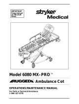
Serial Number
HEAD END
Figure 1 - Cot Serial Number & Location
Introduction
Return To Table of Contents

8 6500-309-001 REV A www.stryker.com
WARNING / CAUTION / NOTE DEFINITION
The words WARNING, CAUTION and NOTE carry special meanings and should be carefully reviewed.
WARNING
Alerts the reader about a situation, which if not avoided, could result in death or serious in-
jury. It may also describe potential serious adverse reactions and safety hazards.
CAUTION
Alerts the reader of a potentially hazardous situation, which if not avoided, may result in minor or moderate injury to
the user or patient or damage to the equipment or other property. This includes special care necessary for the safe
and effective use of the device and the care necessary to avoid damage to a device that may occur as a result of use
or misuse.
NOTE
This provides special information to make maintenance easier or important instructions clearer.
Introduction
Return To Table of Contents

www.stryker.com 6500-309-001 REV A 9
Symbols
Warning, consult accompanying documentation
Type B Equipment: equipment providing a particular degree of protection against electric shock,
particularly regarding allowable leakage current and reliability of the protective earth connection.
Internally Powered Equipment: Equipment able to operate from an internal (removable) electric power
source.
Mode of Operation: 10% (1 Min. On / 5 Min. Off)
Protection from powerful jets.
Dangerous Voltage Symbol
Medical Equipment Classified by Underwriters Laboratories Inc. With Respect to Electric Shock, Fire, and
Mechanical Hazards Only in Accordance with UL 60601−1, and CAN/CSA C22.2 No. 601.1.
Safe Working Load Symbol
In accordance with European Directive 2002/96/EC on Waste Electrical and Electronic Equipment, this
symbol indicates that the product must not be disposed of as unsorted municipal waste, but should be
collected separately. Refer to your local distributor for return and/or collection systems available in your
country.
IPX6
Pinch Point
Extend
Retract
Return To Table of Contents

10 6500-309-001 REV A www.stryker.com
Warranty
Stryker EMS, a division of the Stryker Corporation, offers one warranty option in the United States:
Two (2) year parts and labor. Stryker EMS warrants to the original purchaser that its products
should be free from manufacturing non-conformances that affect product performance and
customer satisfaction for a period of two (2) years after date of delivery. Stryker’s obligation
under this warranty is expressly limited to supplying replacement parts and labor for, or
replacing, at its option, any product that is, in the sole discretion of Stryker, found to be
defective. Expendable components, i.e. mattresses, restraints, I.V. poles, storage nets, storage
pouches, O2 straps, and other soft goods, have a one (1) year limited warranty.
Stryker Medical EMS products are designed for a 7 year expected service life under normal
use, conditions, and with appropriate periodic maintenance as described in the maintenance
manual for each device. Stryker warrants to the original purchaser that the welds on its EMS
products will be free from structural defects for the expected 7 year life of the EMS product as
long as the original purchaser owns the product. Original purchasers will also obtain a three
(3) year limited parts warranty for the X-frame components of the POWER PRO cot and a three
(3) year limited power train warranty covering the motor pump assembly and hydraulic cylinder
assembly. Stryker’s obligation under this three (3) year limited warranty is expressly limited to
supplying replacement parts and labor for, or replacing, at its option, any part that is, in the sole
discretion of Stryker, found to be defective.
If Stryker requests, products or parts for which an original purchaser makes a warranty claim,
the purchaser shall return the product or part prepaid freight to Stryker’s factory.
Any improper use or alteration or repair by unauthorized service providers in such a manner
as in Stryker’s judgment affects the product materially and adversely, shall void this warranty.
Any repair of Stryker products using parts not provided or authorized by Stryker shall void this
warranty. No employee or representative of Stryker is authorized to change this warranty in
any way.
This statement constitutes Stryker EMS’s entire warranty with respect to the aforesaid
equipment. STRYKER MAKES NO OTHER WARRANTY OR REPRESENTATION EITHER
EXPRESSED OR IMPLIED, EXCEPT AS SET FORTH HEREIN. THERE IS NO WARRANTY OF
MERCHANTABILITY AND THERE ARE NO WARRANTIES OF FITNESS FOR ANY PARTICULAR
PURPOSE. IN NO EVENT SHALL STRYKER BE LIABLE HEREUNDER FOR INCIDENTAL OR
CONSEQUENTIAL DAMAGES ARISING FROM OR IN ANY MANNER RELATED TO SALES OR
USE OF ANY SUCH EQUIPMENT.
DeWALT
®
Product Warranty
Any DeWALT
®
product purchased from Stryker EMS is covered for a period of one (1) year
after date of delivery. Stryker’s obligation under this warranty is expressly limited to supplying
replacement parts and labor for, or replacing, at its option, any product that is, in the sole
discretion of Stryker, found to be defective.
Return To Table of Contents

www.stryker.com 6500-309-001 REV A 11
Warranty
STRYKER EMS RETURN POLICY
Cots, Stair Chairs, Evacuation Chairs, Cot Fasteners and Aftermarket Accessories may be
returned up to 180 days of receipt if they meet the following guidelines:
Prior to 30 Days
• 30daymoneybackguaranteeineffect
• StrykerEMSisresponsibleforallcharges
• Returnswillnotbeapprovedonmodifieditems
Prior to 90 Days
• Productmustbeunused, undamaged and in the original packaging
• Customerisresponsiblefora10%restockingfee
Prior to 180 Days
• Productmustbeunused, undamaged and in the original packaging
• Customerisresponsiblefora25%restockingfee
RETURN AUTHORIZATION
Merchandise cannot be returned without approval from the Stryker Customer Service
Department. An authorization number will be provided which must be printed on the returned
merchandise. Stryker reserves the right to charge shipping and restocking fees on returned
items.
SPECIAL, MODIFIED, OR DISCONTINUED ITEMS NOT SUBJECT TO RETURN.
DAMAGED MERCHANDISE
ICC Regulations require that claims for damaged merchandise must be made with the carrier
within fifteen (15) days of receipt of merchandise. DO NOT ACCEPT DAMAGED SHIPMENTS
UNLESS SUCH DAMAGE IS NOTED ON THE DELIVERY RECEIPT AT THE TIME OF RECEIPT.
Upon prompt notification, Stryker will file a freight claim with the appropriate carrier for damages
incurred. Claim will be limited in amount to the actual replacement cost. In the event that this
information is not received by Stryker within the fifteen (15) day period following the delivery of
the merchandise, or the damage was not noted on the delivery receipt at the time of receipt,
the customer will be responsible for payment of the original invoice in full.
Claims for any short shipment must be made within thirty (30) days of invoice.
INTERNATIONAL WARRANTY CLAUSE
This warranty reflects U.S. domestic policy. Warranty outside the U.S. may vary by country.
Please contact your local Stryker Medical representative for additional information.
PATENT INFORMATION
products are covered by one or more of the following patents:
United States 5,575,026 6,276,010 6,648,343 6,908,133 6,796,757
5,537,700 6,125,485 6,735,794 7,100,224 7,398,571
D 527,103
Other Patents Pending
Return To Table of Contents

12 6500-309-001 REV A www.stryker.com
Summary of Safety Precautions
The following is a list of safety precautions that must be observed when operating or servicing this unit. The precautions
are repeated throughout the manual, where applicable. Carefully read this list before using or servicing the unit.
WARNINGS
Do not modify the ambulance cot or any components of the cot, including the hydraulic unit. Modifying the product •
can cause unpredictable operation resulting in injury to the patient or operator. Modifying the product will also void
its warranty.
The in-fastener shut-off module must be positioned properly before placing the ambulance cot into EMS service. •
Failure to install the in-fastener shut-off module may cause injury to the patient or operator and/or damage to the
vehicle.
It is the responsibility of the cot operator to ensure the ambulance cot being used in the Stryker cot fastener •
system meets the installation specifications listed on page 23. Injury may result if a non-compatible ambulance cot
is used in the Stryker cot fastener system.
Have the vehicle safety hook installed by a certified mechanic. Improper safety hook installation can result in injury •
to the patient or operator and/or damage to the cot.
Failure to install the vehicle safety hook can result in injury to the patient or operator. Install and use the safety •
hook as described in this manual. To avoid injury, verify the safety bar has engaged the safety hook before
removing the ambulance cot from the patient compartment.
Install the vehicle safety hook at least 1/8" (3 mm) from the edge of the rear ambulance door. After installation, •
verify that the undercarriage locks in the load position without contacting the emergency vehicle bumper.
The ambulance cot must have at least 5/8" (1,6 mm) of clearance between the emergency vehicle bumper and •
the ambulance cot to disengage the safety bar when unloading the product from the ambulance. Verify that the
product is locked in a rolling position before disengaging the safety bar from the safety hook (if equipped).
To avoid accidental release of the Pedi-Mate™, and possible injury to the infant, ensure that the restraint buckle •
is located away from obstructions on the ambulance cot or accessories.
Never apply the optional wheel lock(s) while a patient is on the ambulance cot. Tipping could occur if the •
ambulance cot is moved while wheel locks are applied, resulting in injury to the patient or operator and/or damage
to the product.
Never install or use wheel locks on an ambulance cot with excessively worn wheels. Installing or using wheel locks •
on wheels with less than a 6" (16 cm) diameter could compromise the holding ability of the wheel lock, resulting
in injury to the patient or operator and/or damage to the product or other equipment.
To avoid risk of electric shock, never attempt to open the battery pack for any reason. If the battery pack case •
is cracked or damaged, do not insert it into the charger. Return damaged battery packs to a service center for
recycling.
Do not remove the battery when the ambulance cot is activated.•
Avoid contact with a wet battery or battery enclosure. Contact may cause injury to the patient or operator.•
When the optional head-end storage flat is being used, ensure it does not interfere with the operation of the •
retractable head section, safety bar and safety hook. Injury to the patient or operator could result.
Improper usage of the ambulance cot can cause injury to the patient or operator. Operate the ambulance cot only •
as described in this manual.
Entanglement in powered ambulance cot mechanisms can cause serious injury. Operate the ambulance cot only •
when all persons are clear of the mechanisms.
Practice changing height positions and loading and unloading the ambulance cot until operation of the product is •
fully understood. Improper use can cause injury.
Do not allow untrained assistants to assist in the operation of the ambulance cot. Untrained technicians/assistants •
can cause injury to the patient or themselves.
Ensure proper hand placement on hand grips. Hands should be clear of red safety bar pivots while loading and •
unloading the cot.
Do not ride on the base of the ambulance cot. Damage to the product could occur, resulting in injury to the patient •
or operator.
Grasping the ambulance cot improperly can cause injury. Keep hands, fingers and feet away from moving parts. •
Return To Table of Contents

www.stryker.com 6500-309-001 REV A 13
WARNINGS (CONTINUED)
Transporting the cot sideways can cause the cot to tip, resulting in possible damage to the product and/or injury to •
the patient or operator. Transporting the cot in a lowered position, head or foot end first, will minimize the potential
of a cot tip.
Any emergency vehicle to be used with this ambulance cot • must have the in-fastener shut-off system installed.
Always use all restraint straps to secure the patient to the ambulance cot. An unrestrained patient may fall from •
the ambulance cot and be injured.
Do not attach restraints to the base or cross tubes, improper restraint attachment could result in damage to the •
cot further resulting in injury to the patient or operator.
Never leave a patient unattended on the ambulance cot or injury could result. Hold the ambulance cot securely •
while a patient is on the cot.
Siderails are not intended to serve as a patient restraint device. Refer to • pages 28 and 30 for proper restraint strap
usage. Failure to utilize the siderails properly could result in patient injury.
High obstacles such as curbing, steps or rough terrain can cause the ambulance cot to tip, possibly causing injury •
to the patient or operator. Transporting the cot in lower positions can reduce the potential of a cot tip. If possible,
obtain additional assistance (see page 55 for a reference chart) or take an alternate route.
Whenever the weight of the ambulance cot and patient is off the wheels, the ambulance cot will • automatically
enter the high speed retract mode if the retract button is pressed.
Once the weight is off the ground, the operator(s) must support the load of the patient, ambulance cot and any •
accessories. Failure to support the load properly may cause injury to the patient or operator.
To avoid injury, verify the safety bar has engaged the safety hook before removing the ambulance cot from the •
patient compartment.
Do not pull or lift on the safety bar when unloading the ambulance cot. Damage to the safety bar could result and •
injury to the patient or operator could occur.
Do not press the extend (+) button until the safety bar engages the safety hook.•
To avoid injury, always verify that the head section is locked into place prior to operating the ambulance cot (see •
page 54). The head section must be extended and locked into position before loading/unloading the ambulance
cot.
When using a standard ambulance cot fastener, do not load the cot into the vehicle with the head section retracted. •
Loading the cot with the head section retracted may cause the product to tip or not engage properly in the cot
fastener, possibly causing injury to the patient or operator and/or damage to the cot.
The one person loading and unloading procedures are for use only with an empty ambulance cot. Do not use the •
procedures when loading/unloading a patient. Injury to the patient or operator could result.
Do not attempt to operate the ambulance cot when loaded into a cot fastener. The in-fastener shut-off is • only a
means for disabling the electronic functionality. Damage to the product or injury to the patient or operator may
occur.
In-fastener shut-off must be installed in all ambulances in which the cot will be used.•
Use any appropriate personal safety equipment (goggles, respirator, etc.) to avoid the risk of inhaling contagion. •
Use of power washing equipment can aerate contamination collected during the use of the ambulance cot.
Failure to properly clean or dispose of contaminated mattress or other ambulance cot components will increase •
the risk of bloodborne pathogens and may cause injury to the patient or operator.
Hydraulically raising or lowering the cot may temporarily affect electronic patient monitoring equipment. For best •
results, patient monitoring should be conducted when the cot is idle.
SOME CLEANING PRODUCTS ARE CORROSIVE IN NATURE AND MAY CAUSE DAMAGE TO THE PRODUCT IF •
USED IMPROPERLY. If the products described above are used to clean Stryker patient care equipment, measures
must be taken to insure the cots are wiped with clean water and thoroughly dried following cleaning. Failure to
properly rinse and dry the cots will leave a corrosive residue on the surface of the cots, possibly causing premature
corrosion of critical components.
Escaping fluid under pressure can penetrate the skin causing serious injury. Avoid the hazard by relieving pressure •
before disconnecting hydraulic or other lines. Tighten all connections before applying pressure. If an accident
occurs, see a doctor immediately. Any fluid injected into the skin must be surgically removed within a few hours
or gangrene may result. Doctors unfamiliar with this type of injury should reference a knowledgeable medical
source.
Summary of Safety Precautions
Return To Table of Contents

14 6500-309-001 REV A www.stryker.com
CAUTIONS
Set the cot height limit to the proper stop height prior to operation.•
Installation of the safety hook should be done by a certified mechanic familiar with ambulance construction. •
Consult the vehicle manufacturer before installing the safety hook and be sure the installation of the safety hook
does not damage or interfere with the brake lines, oxygen lines, fuel lines, fuel tank or electrical wiring of the
vehicle.
Ensure that restraints are not entangled in the base frame when raising and lowering the cot. •
Wheel locks are only intended to help prevent the ambulance cot from rolling while unattended. Wheel locks may •
not provide sufficient resistance on all surfaces or under loads.
The ambulance cot fastener comes preconfigured for an X-Frame cot, if the fastener has been configured for an •
H-frame style cot, the cot retaining post must be adjusted to accommodate the fastener.
Only use the battery and charger as specified.•
The Power-PRO™ XT is not for use with an AC adaptor.•
Ensure that the battery is charged prior to placing into service. An uncharged or depleted battery may cause poor •
ambulance cot performance.
A preventative maintenance program should be established for all Stryker EMS equipment. Preventative maintenance •
may need to be performed more frequently based on the usage level of the product. Close attention should be
given to safety features including, but not limited to:
Hydraulic power mechanism•
All electrical controls return to off or neutral position when released•
For additional maintenance information, refer to the preventative maintenance section.•
Do not store items under the ambulance cot mattress. Storing items under the mattress can interfere with the •
operation of the ambulance cot.
The weight of the equipment in the head end storage flat (if equipped) must not exceed 40 pounds (18 kg). •
The weight of the equipment in the pocketed backrest storage pouch (if equipped) must not exceed 20 pounds •
(9 kg).
To avoid damage to the equipment hook, the weight of the accessories or equipment must not exceed 20 pounds •
(9 kg).
The weight of the I.V. bags or equipment must not exceed 40 pounds (18 kg) for usage on the I.V. poles •
(if equipped).
The weight of the oxygen bottle cylinder and/or other equipment must not exceed 40 pounds (18 kg) with the •
permanent foot-end oxygen bottle holder (if equipped). Oxygen bottle cylinder should not be stored on the cot or
on the oxygen holder when in the ambulance vehicle.
The weight of the removable oxygen bottle holder and/or other equipment must not exceed 25 pounds (11.3 kg) •
Before operating the cot, clear any obstacles that may interfere and cause injury to the operator or patient.•
The ambulance cot can be set at any height position. Establish the required load height for the ambulance cot •
prior to placing the unit into service.
Loading, unloading or changing the position of a loaded ambulance cot requires a minimum of• two trained
operators. The operator(s) must be able to lift the total weight of the patient, cot and any other items on the cot
(if additional assistance is needed, see page 53 for a reference chart).
When unloading the ambulance cot from the patient compartment, ensure the caster wheels are safely set on the •
ground or damage to the product may occur.
Do not “jog” the ambulance cot past the established load height of the product when the safety bar engages the •
vehicle safety hook or damage may occur to the product.
Remove the battery if the cot is not going to be used for an extended period of time (over 24 hours).•
Remove the battery before washing the cot.•
Do not steam clean or ultrasonically clean this ambulance cot. Maximum water temperature should not exceed •
180 °F/82 °C. Maximum air dry temperature (cart washers) is 240 °F/115 °C. Maximum water pressure should not
exceed 1500 psi/130.5 bar. If a hand held wand is being used to wash the unit, the pressure nozzle must be kept
a minimum of 61 centimeters from the unit. Towel dry all casters and interface points. Failure to comply with these
instructions may invalidate any/all warranties.
Summary of Safety Precautions
Return To Table of Contents

www.stryker.com 6500-309-001 REV A 15
Summary of Safety Precautions
CAUTIONS (CONTINUED)
Improper maintenance can cause injury or damage to the product. Maintain the ambulance cot as described in this •
manual. Use only Stryker approved parts and maintenance procedures. Using unapproved parts and procedures
could cause unpredictable operation and/or injury and will void the product warranty.
Failure to use authorized parts, lubricants, etc. could cause damage to the ambulance cot and will void the •
warranty of the product.
Hydraulic hose connections and lines can fail due to physical damage, kinks, age, and exposure. Check hoses and •
lines regularly to avoid damage to the cot. Check and tighten loose connections.
Hydraulic fluid connections can loosen due to physical damage and vibration. Check and tighten loose •
connections.
When charging batteries in an ambulance vehicle, locate the charger either in the forward cab or an enclosed •
compartment (i.e. cabinet).
Do not lubricate the bearings in the X-frame as it will degrade the performance of the Power-PRO™ XT ambulance •
cot and may void its warranty.
NOTES
This manual should be considered a permanent part of the ambulance cot and should remain with the product •
even if the cot is subsequently sold.
Adjustment of the rail clamp assembly may be required in order to compensate for any variation in the cot retaining •
post position depending on the ambulance cot manufacturer and model number.
These are general instructions for installation of the Pedi-Mate™. Safe and proper use of the Pedi-Mate™ is solely •
at the discretion of the user. Stryker recommends all users be trained on the proper use of the Pedi-Mate™ before
using it in an actual situation.
If the arrow on the bottom bracket of the retaining post points toward the head end of the cot, the retaining post •
is set for an X-frame style cot. If the arrow points toward the foot end of the cot the post is set for an H-frame
style cot.
If the push button switch remains activated, the motor will remain halted until the operator releases the button. •
Once the push button is released, depress the appropriate button to “jog” the cot height in either direction.
Add an additional 1/2" (1,3 cm) inch to your deck height measurement to allow for variations with patient weight •
and equipment added to the cot.
The operators must lift the cot slightly off the ground to use the manual extend or retract while a patient is on the •
cot.
Batteries slowly lose power when not on the charger.•
Failure to follow the cleaning directions when using the specified types of cleaners may void this product’s •
warranty.
Activation of the manual release may cause the ambulance cot to drop slowly if less than 40 pounds (18 kg) are •
on the cot.
When operating the manual release, avoid rapid lifting or lowering of the base or movement may appear sluggish; •
lift with a slow constant motion.
In order to achieve the optimal performance of the Power-PRO™ XT, center the patient weight within the width of •
the cot.
Return To Table of Contents


www.stryker.com 6500-309-001 REV A 17
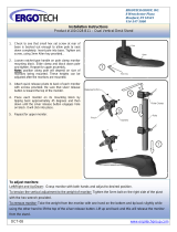
Component Identification
Short Safety Hook
Stryker part number
6060-036-017
Backrest
Foot Rest Release
Handle
Backrest Adjustment Handle
HEAD END
Battery Release
Siderail Release
Retractable
Head Section
Head Section
Release
Manual Release
Battery
Leg Rest
Loading Wheels
Height
Sensor
Housing
Hydraulic Unit
Wheel Lock
(Optional)
Transport Wheels
Transport Wheels
Cot Retaining Post
J Safety Hook
Stryker part number
6092-036-018
Long Safety Hook
Stryker part number
6060-036-018
Lifting Bar
Height Adjustment
Switches
Figure 3 - Cot Components
Return To Table of Contents

18 6500-309-001 REV A www.stryker.com
Product Inspection
GENERAL INSPECTION
The condition of the ambulance cot is the responsibility of the owner. It is important that the ambulance cot is working
properly before the product is put into service. Have a qualified service person use the following list and the operation
instructions to check the ambulance cot before the product is put into service.
Unpack the cartons and check all items for proper operation.
Item Routine Page(s)
Battery Unpack batteries and charger
Charge battery according to DeWA LT
®
instructions
P/N 6500-001-206
CAUTION
When charging batteries in an ambulance vehicle, locate the charger either in the forward cab or an enclosed
compartment (i.e. cabinet).
Prior to checking the features and condition of the cot, the battery must be charged until the red LED lights continuously
to ensure a full charge. Refer to the DeWALT
®
instructions for further charging information.
Once the battery is fully charged, inspect the ambulance cot for the following points:
Item Routine Page(s)
Battery Charge spare battery (if necessary) according to DeWALT
®
instructions.
P/N 6500-001-206
Install battery into foot-end enclosure, battery indicator operates. 57
Ensure the battery remains firmly secured. 57
Release and remove battery from foot-end enclosure. 57
Reinstall battery into foot-end enclosure. 57
Hydraulics Inspect motor mount, all fasteners secure. 118
Check cylinder attachments at both ends, all fasteners secure. 118
Inspect main cable, all connections secure. 118
Inspect hoses and cylinder seal for leaks. 118
Electronic
Controls
Check battery indicator, charged. 37
Extend cot to raised position. 55
Verify ”jog” function operating smoothly. 55
Lower to retracted position, cot secures in a mid-height position
(motor does not operate).
55
Determine and set ambulance vehicle load height 21
Check high speed retract. 47
Extend cot to full height, no drift. 55
Manual Release Verify the manual release lever functions properly, adjust accordingly. 51
With the cot empty, check the raise/lower function. 51
With the cot loaded with a minimum of 45 kg, check the raise/lower
function.
51
With the cot loaded with a minimum of 45 kg, check the load/unload
function.
48
Return To Table of Contents

www.stryker.com 6500-309-001 REV A 19
Product Inspection
Item Routine Page(s)
Litter All fasteners secure (reference all assembly drawings).
All welds intact, not cracked or broken.
No bent, broken, or damaged components.
Inspect hand grips, no defects or tears.
Verify siderails operate and latch properly. 36
Verify backrest cylinder operates properly through range of motion. 36
Verify the leg rest operates properly. 35
Install body restraints. Restraints intact and operating properly. 28 - 30
No rips or tears in mattress cover.
Head Section All fasteners secure (reference all assembly drawings).
No bent or broken tubing or sheet metal.
Verify the head section extends and retracts properly. 56
Inspect grip on lift bar, no defects or tears.
Load wheels are secure and roll freely.
Verify the safety bar operates properly. 24
Base All fasteners secure (reference all assembly drawings).
All welds intact, not cracked or broken.
No bent, broken, or damaged components.
Wheels and Tires No debris in wheels.
All wheels secure, rolling and swiveling properly.
Operate wheel locks (if equipped) - wheel secure when engaged,
rolls freely when disengaged.
33 - 34
Cot Fastener Inspect the cot retaining post, fasteners secure. 34
Install in-fastener shut-off module.
Determine and set in-fastener shut-off position.
Verify the ambulance cot and cot fastener fit and function properly.
24
Install vehicle safety hook. 25 - 27
Verify the safety bar engages the vehicle safety hook properly. 24
Accessories Verify I.V. pole (if equipped) operates properly. 42 - 43
Verify foot-end oxygen bottle holder (if equipped) operates properly.
Verify removable oxygen bottle holder (if equipped) operates properly.
Verify Pedi-Mate™ restraint package (if equipped) operates properly. 31 - 32
Verify accessory hook (if equipped) is installed properly. 41
Verify head extension with pillow (if equipped) installed properly.
Verify pocketed backrest storage pouch (if equipped) installed properly. 40
Head-end storage flat (if equipped) installed properly. 39
Verify pillow (if equipped) included.
Verify 36" restraint extender (if equipped) is included. 30
Verify the Bariatric transfer flat (if equipped) is included. 45
Return To Table of Contents

20 6500-309-001 REV A www.stryker.com
Setup Procedures
Ensure that all shipping and packaging materials have been removed from the product(s) prior to use.
The patient compartment of the vehicle in which the ambulance cot will be used must have:
• Asmoothrearedgeforcotloading.
• Alevelfloorlargeenoughforthefoldedcot.
• Stryker6370/6374/6377/6378/6379or6371/6375crashstablecotfastener(notincluded).
• In-fastenershut-offmoduleinstalledandpositionedproperly.
• Spacetoinstallthesafetyhook.
When necessary, modify the vehicle to fit the cot. Do not modify the cot.
WARNING
Do not modify the Power-PRO™ XT ambulance cot or any components of the cot, including the hydraulic unit. •
Modifying the product can cause unpredictable operation resulting in injury to the patient or operator. Modifying
the product will also void its warranty.
Any emergency vehicle to be used with this ambulance cot • must have the in-fastener shut-off system installed.
Refer to DeWALT
®
manual (Stryker part number 6500-001-206) for battery and charger operation.
NOTE
This manual should be considered a permanent part of the ambulance cot and should remain with the product •
even if the cot is subsequently sold.
Stryker continually seeks advancements in product design and quality. Therefore, while this manual contains the •
most current product information available at the time of printing, there may be minor discrepancies between your
ambulance cot and this manual. If you have any questions, please contact Stryker Customer Service or Technical
Support at (800) 327-0770 or (269) 324-6500.
Return To Table of Contents
/