Page is loading ...

ASSEMBLY INSTRUCTIONS
Entire Contents © Copyright 2004 HCAZ3065 for HCAA2101 V1.0
Wingspan: 71 in [1805mm]
Weight: 7–8 lb [3180–3630 g]
Length: 55 in [1400mm]
Wing Area: 888 sq in [57 dm
2
]
Radio: Futaba
®
Skysport 6
Engine: O.S.
®
65LA
Wing Loading: 18–21 oz/sq ft [55–64 g/dm
2
]
Hobbico
®
guarantees this kit to be free from defects in
both material and workmanship at the date of purchase.
This warranty does not cover any component parts
damaged by use or modification. In no case shall
Hobbico’s liability exceed the original cost of the
purchased kit. Further, Hobbico reserves the right to
change or modify this warranty without notice.
In that Hobbico has no control over the final assembly or
material used for final assembly, no liability shall be
assumed nor accepted for any damage resulting from the
use by the user of the final user-assembled product. By
the act of using the user-assembled product, the user
accepts all resulting liability.
If the buyer is not prepared to accept the liability
associated with the use of this product, the buyer is
advised to return this kit immediately in new and unused
condition to the place of purchase.
To make a warranty
claim, send the defective
part or item to Hobby
Services at this address.
Include a letter stating your name, return shipping address, as
much contact information as possible (daytime telephone
number, fax number, e-mail address), a detailed description
of the problem and a photocopy of the purchase receipt.
Upon receipt of the package the problem will be evaluated
as quickly as possible.
READ THIS MANUAL BEFORE
STARTING CONSTRUCTION.
IT CONTAINS IMPORTANT
INSTRUCTIONS AND WARNINGS
CONCERNING THE ASSEMBLY
AND USE OF THIS MODEL.
WARRANTY
Hobby Services
3002 N. Apollo Dr. Suite 1
Champaign IL 61822
USA
1610 Interstate Drive
Champaign, Illinois
(217) 398-8970 ext. 2
™

2
INTRODUCTION . . . . . . . . . . . . . . . . . . . . . .2
SAFETY PRECAUTIONS . . . . . . . . . . . . . . . . . .2
KIT CONTENTS . . . . . . . . . . . . . . . . . . . . . . . .3
ORDERING REPLACEMENT PARTS . . . . . . . . .4
REPLACEMENT PARTS LIST . . . . . . . . . . . . . . .4
FIELD EQUIPMENT . . . . . . . . . . . . . . . . . . . . .4
PREPARATIONS . . . . . . . . . . . . . . . . . . . . . . .5
ASSEMBLE THE FUSELAGE . . . . . . . . . . . . . . . .5
ASSEMBLE THE WING . . . . . . . . . . . . . . . . . . .7
PREPARE THE MODEL FOR FLYING . . . . . . . . .8
Check the Screws . . . . . . . . . . . . . . . . . . . .8
Charge the Batteries . . . . . . . . . . . . . . . . . .8
Center the Control Surfaces . . . . . . . . . . . . .8
Check the Control Directions . . . . . . . . . . .9
Set the Control Throws . . . . . . . . . . . . . . . .9
Adjust the Throttle . . . . . . . . . . . . . . . . . . .10
Balance the Model . . . . . . . . . . . . . . . . . .11
Identify Your Model . . . . . . . . . . . . . . . . . .12
Balance Propellers . . . . . . . . . . . . . . . . . .12
Charge the Batteries . . . . . . . . . . . . . . . . .13
Gather Your Tools & Spare Parts . . . . . . . . .13
FLIGHT PREPARATION . . . . . . . . . . . . . . . . .13
Check the Controls . . . . . . . . . . . . . . . . . .13
Range Check the Radio . . . . . . . . . . . . . . .14
Ground Check . . . . . . . . . . . . . . . . . . . . .14
ENGINE SAFETY PRECAUTIONS . . . . . . . . . .14
AMA SAFETY CODE . . . . . . . . . . . . . . . . . . .14
FLYING . . . . . . . . . . . . . . . . . . . . . . . . . . . . .15
Taxiing . . . . . . . . . . . . . . . . . . . . . . . . . . .15
Takeoff . . . . . . . . . . . . . . . . . . . . . . . . . . .15
Flight . . . . . . . . . . . . . . . . . . . . . . . . . . . .16
Landing . . . . . . . . . . . . . . . . . . . . . . . . . .16
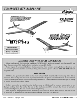
Congratulations and thank you for purchasing the
Hobbistar .60 Select. You have made the right
decision by purchasing a “real” model airplane
with an O.S.
®
.65 LA engine and a genuine Futaba
®
6-channel radio.
There are two parts to this manual. The first part is a
short, easy-to-follow assembly section. The second
part, Setup, takes you through the initial
adjustments and flight preparation. Do not overlook
any of the important setup procedures and be sure
to follow the instructions all the way to the end of
this manual.
We urge you to join the AMA (Academy of Model
Aeronautics) and a local R/C club. The AMA is the
governing body of model aviation and membership is
required to fly at AMA clubs. Though joining the AMA
provides many benefits, one of the primary reasons to
join is liability protection. Coverage is not limited to
flying at contests or on the club field. It even applies to
flying at public demonstrations and air shows. Failure
to comply with the Safety Code (excerpts printed in the
back of the manual) may endanger insurance coverage.
Additionally, training programs and instructors are
available at AMA club sites to help you get started the
right way. There are over 2,500 AMA chartered clubs
across the country. Contact the AMA at the address or
toll-free phone number below:
5151 East Memorial Drive
Muncie, IN 47302-9252
Tele. (800) 435-9262
Fax (765) 741-0057
Or via the Internet at:
http://www.modelaircraft.org
IMPORTANT!!!
Two of the most important things you can do to
preserve the radio controlled aircraft hobby are to
avoid flying near full-scale aircraft and avoid flying
near or over groups of people.
1. Your Hobbistar .60 Select should not be
considered a toy, but rather a sophisticated,
working model that functions very much like a full-
size airplane. Because of its performance
capabilities, the Hobbistar .60, if not assembled
and operated correctly, could possibly cause injury
to yourself or spectators and damage to property.
2. You must assemble the model according to the
instructions. Do not alter or modify the model, as
doing so may result in an unsafe or unflyable model. In
a few cases the instructions may differ slightly from the
photos. In those instances the written instructions
should be considered as correct.
Protect your model, yourself &
others... Follow these Important
Safety Precautions
AMA
Introduction
Table of Contents

8
9
1
2
3
4
5
6
7
3
Kit Inspection
Kit Contents
3. You must check the operation of the model before
every flight to insure that all equipment is operating
and that the model has remained structurally
sound. Be sure to check clevises or other
connectors often and replace them if they show any
signs of wear or fatigue.
4. If you are not an experienced pilot or have not
flown this type of model before, we recommend
that you get the assistance of an experienced pilot
in your R/C club for your first flights. If you’re not a
member of a club, your local hobby shop has
information about clubs in your area whose
membership includes experienced pilots.
Remember: Take your time and follow the
instructions to end up with a well-built model.
We, as the kit manufacturer, provide you with a
top quality, thoroughly tested kit and
instructions, but ultimately the quality and
flyability of your finished model depends on how
you build it; therefore, we cannot in any way
guarantee the performance of your completed
model, and no representations are expressed or
implied as to the performance or safety of your
completed model.
Before starting to build, take an inventory of this kit to make sure it is complete, and inspect the parts to
make sure they are of acceptable quality. If any parts are missing or are not of acceptable quality, or if you
need assistance with assembly, contact Product Support. When reporting defective or missing parts, use
the part names exactly as they are written in the Kit Contents list.
Hobbico Product Support • 3002 N Apollo Drive, Suite 1 • Champaign, IL 61822
Telephone: (217) 398-8970, ext. 2 • Fax: (217) 398-7721
E-mail: [email protected]
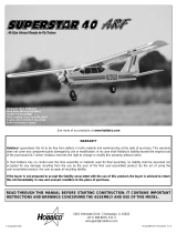
Items photographed
1. Left wing
2. Right wing
3. Fin & rudder
4. Fuselage (servos, receiver &
engine preinstalled
5. Spinner
6. Langing gear
7. Stab with elevators
8. Misc. hardware (Itemized after
this list)
9. Radio system & charger.
Miscellaneous hardware list
(1) 9 x 207mm metal wing joiner
(2) 56mm plastic stab bolts
(2) Metal wing joiner straps
(2) Nylon landing gear straps
(4) Plastic wing dowel plates
(2) 7 x120mm wood dowels
(8) 2.5 x 8mm screws for mounting
the plastic wing dowel shrouds
(4) 3 x 12mm screws for mounting
the landing gear straps
(8) Rubber bands
(4) Nylon clevises (These threaded
clevises are in addition to the clevises
already installed on the pushrods. These
are provided as extras.)

Replacement parts for the Hobbistar .60 Select ARF
are available using the order numbers in the
Replacement Parts List that follows. The fastest,
most economical service can be provided by your
hobby dealer or mail-order company.
To locate a hobby dealer, visit the Hobbico web site at
www.hobbico.com. Choose “Where to Buy” at the
bottom of the menu on the left side of the page. Follow
the instructions provided on the page to locate a U.S.,
Canadian or International dealer. If a hobby shop is not
available, replacement parts may also be ordered from
Tower Hobbies at www.towerhobbies.com or by
calling toll free (800) 637-6050.
Parts may also be ordered directly from Hobby Services
by calling (217) 398-0007, or via facsimile at (217)
398-7721, but full retail prices and shipping and
handling charges will apply. Illinois and Nevada
residents will also be charged sales tax. If ordering via
fax, include a Visa
®
or MasterCard
®
number and
expiration date for payment.
Mail parts orders and payments by personal check
to:
Hobby Services
3002 N Apollo Drive, Suite 1
Champaign IL 61822
Be certain to specify the order number exactly as
listed in the Replacement Parts List. Payment by
credit card or personal check only; no C.O.D.
If additional assistance is required for any reason
contact Product Support by e-mail at
[email protected], or by telephone at
(217) 398-8970.
Order
Number Description How to purchase
HCAA3120 . . .Fuselage Set . . . .Hobby Supplier
HCAA3121 . . . .Wing Set . . . . .Hobby Supplier
HCAA3122 . . . . .Tail Set . . . . . .Hobby Supplier
HCAA3123 . .Landing Gear . . .Hobby Supplier
HCAA3124 . . . .Decal Set . . . . .Hobby Supplier
Missing pieces . . . . . . . . . . . . . .Product Support
Instruction manual . . . . . . . . . . .Product Support
Full-size plans . . . . . . . . . . . . . . .Not available
When ready to fly, you'll need some additional
equipment to fuel the plane and start the engine.
The most important items include an electric starter,
12 volt battery, or chicken stick, fuel pump (electric
or hand-crank), fueling lines and fittings and a 1.5
volt glow plug igniter. Your flight instructor will
probably let you share his equipment for a while,
but eventually you'll need your own. Visit your local
hobby dealer or see the Hobbico catalog for a full
selection, descriptions and pricing.
Field Equipment
Replacement Parts ListOrdering Replacement Parts
4

Upon inspection of your airplane you may find that
the covering has a few wrinkles. These can be easily
removed with a modeling iron. Set the iron at a
medium to medium/high heat setting. Work the iron
slowly over the wrinkles allowing the heat to shrink
the film. As the film begins to shrink, lightly apply
pressure with the iron to bond the film to the wood
under the covering.
❏ 1. Insert the landing gear into the holes in the
landing gear plate.
❏2. Secure the landing gear to the fuselage with two
nylon landing gear straps and four 3 x12mm screws.
❏3. Insert the 7 x 120mm hardwood dowels into the
holes at the front and rear of the fuselage center.
❏ 4. Install four plastic wing dowel plates over the
ends of the dowels. Secure the plates to the dowels
with 2.5 x 8mm screws.
❏5. Slide the horizontal stab into position at the back
of the fuselage aligning the holes in the center of the
stab with the holes in the bottom of the fuselage.
Assemble the Fuselage
Preparations
5

❏6. Insert the vertical fin into the slot in the back of
the fuselage. The metal rods should pass through the
holes in the stab and fuselage.
❏7 Install both of the 56mm plastic stab bolts into the
holes, threading them onto the wires from the stab.
Tighten both of the bolts snugly against the fuselage. Do
not over tighten the bolts or they could strip.
❏ 8. Install the nylon clevis into the outer hole of
the control horn and secure it by sliding the silicone
clevis keeper over the clevis. Do the same for the
rudder clevis.
IMPORTANT!
Do not fly the airplane without the silicone clevis
keepers on the clevises. Flying without silicone clevis
keepers could cause the clevises to fail, possibly
resulting in a crash. Inspect the silicone clevis
keepers and if they show any signs of wear, replace
them with new ones. These can be made by cutting
1/4” lengths of silicone fuel tubing.
6

❏1. Slide the 9 x 207mm metal wing joiner into the
hole in the right wing panel.
❏ 2. Slide the left wing panel onto the metal wing
joiner. Slide the wings together, making sure the
alignment pin in the wing fits into the hole in the
opposite wing panel.
❏ 3. Be sure the wings are tight against each other.
Place the two metal wing joiner straps over the pre-
drilled holes in the bottom of the wing. Secure the
straps to the wing panels with 2.5 x 8mm screws.
❏ 4. Install the aileron clevis to the control horn.
Slide the silicone clevis keeper over the clevis.
HH
HH
oo
oo
tt
tt
TT
TT
ii
ii
pp
pp
Here are two things you might consider to make a
stronger, longer-lasting wing assembly. Both are
very easy but do require the use of glue.
1. Apply epoxy glue to the root rib of each wing
half before sliding the wings together. Once the
wings are pushed tightly against each other,
install the metal wing joiner straps and 2.5 x
8mm screws. Clean any excess epoxy from the
wing with a paper towel and rubbing alcohol.
2. Put some aliphatic glue (any typical white
glue such as Elmers
®
) into the screw holes, then
install the screws. When the glue dries it will be
difficult for the screws to come loose from
vibration or wear.
Assemble the Wing
7

CHECK THE SCREWS
Your Hobbistar .60 Select is nearly a fully assembled
airplane when you remove it from the box. However, it
is a good idea to check the tightness of all of the screws.
Systematically go through the airplane and be sure all
bolts and screws are tight. Start with the engine
compartment followed by the landing gear, radio
compartment, tail surfaces and then the wing. Remove
the spinner and check the propeller nut to be sure it is
tight; then, re-install the spinner.
CHARGE THE BATTERIES
If you have not yet charged the batteries, you may still
proceed. However, as the batteries have not been fully
charged, they may not provide enough power to make
it all the way through the setup procedures. If the
batteries quit working, charge the batteries as described
in the instruction manual for the Futaba radio system
that came with this kit. After you complete the setup
and before flying the airplane be sure to follow the next
charging steps!
IMPORTANT!
Your Hobbistar .60 Select uses NiCd batteries in the
transmitter and receiver. NiCd batteries need to be
exercised or “cycled” to get full capacity from the
batteries before using them. There are several good
electronic cyclers available. The Hobbico Accu-Cycle
™
(HCAP0260) and the Accu-Cycle Elite (HCAP0280) are
two good choices. If you have a battery cycler or if your
instructor has one, it is recommended that you cycle the
batteries at least three times before you fly. If you do not
have access to a battery cycler, we recommend you use
the following procedure to help assure you are getting
full capacity from you batteries.
❏ 1. Charge the transmitter and receiver battery
overnight following the instructions with the
radio system.
❏ 2. Extend the transmitter antenna; turn on the
transmitter and receiver. Using the transmitter, move
the control surfaces. Continue moving the control
surfaces until the servos slow down or quit
functioning. This will take approximately an hour.
❏ 3. Re-charge the batteries and repeat this
procedure. Normally doing this two or three times
will cycle the batteries adequately for safe flying. If,
after repeating this a few times, you are not getting
approximately an hour or more of operating time,
repeat the procedure until you do.
CENTER THE CONTROL SURFACES
Even though the trim levers on the transmitter may
be used to center the control surfaces, you should
start out with the trims centered.
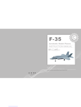
Do the elevator first.
❏ 1. With the transmitter and receiver on, view the
elevator and stab from the end. If the elevator is not
centered, disconnect the clevis from the control horn
on the elevator. Holding the end of the pushrod with
pliers, screw or unscrew the clevis as necessary until
the elevator will be centered when reconnected to
the pushrod. Note: Be sure not to unscrew the clevis
too far. It must remain securely fastened to the end of
the pushrod.
❏2. Center the rudder and both ailerons the same way.
❏ 3. Now that the rudder is centered, center the
nose wheel by adjusting the pushrod in the threaded
connector on the steering arm. Roll the fuselage
along a flat surface (such as your garage, basement
or kitchen floor) to make certain it rolls straight. This
should be done with the transmitter and receiver on.
Make adjustments if necessary. Add a small drop of
threadlocker to the screw and securely tighten to
lock the pushrod into position.
❏ 4. Install a silicone retainer on all the clevises
(elevator, rudder, ailerons, throttle). If you've
misplaced the retainers that came with the model,
use 1/4" [6mm] pieces cut from leftover fuel tubing.
Stabilizer
Elevator
Elevator NOT Centered With Stab
Elevator Centered With Stab
Prepare the Model for Flying
8

CHECK THE CONTROL DIRECTIONS
Move the control sticks on the transmitter as shown
to be certain the controls on the airplane respond in
the correct direction. If any of the controls move the
wrong way, use the servo reversing switches on the
transmitter to make the controls respond correctly. If
necessary, refer to the instructions in the instruction
manual that came with your radio to identify and
operate the reversing switches.
SET THE CONTROL THROWS
The control throws are a measure of how far the
flight controls (elevator, ailerons, rudder) move up
and down (or from side to side). If the controls move
too much, the plane will respond too quickly and be
difficult to control. If the controls do not move
enough, there will not be enough control to fly or
land the model. Due to the great effect the control
throws have on the way a model flies, the control
throws must be set according to the measurements
provided in this manual.
Start with the elevator…
❏1. Turn on the transmitter and receiver. Holding a ruler
up to the trailing edge of the elevator, move the elevator
all the way up using the control stick on the transmitter.
Measure the distance the elevator moves up. Also move
the elevator down and measure the distance. As shown
in the chart that follows, the elevator should move up
1/2" [13mm] and down 1/2" [13mm]. If the elevator
moves up or down more than 1/2" [13mm], the control
throw must be decreased by connecting the pushrod to
a hole further out on the elevator control horn, or by
connecting the pushrod to a hole further in on the
elevator servo arm (as shown in the sketches below). If
the elevator moves up and down less than 1/2" [13mm],
the control throw must be increased by relocating the
pushrods the opposite as described.
Control Throws
Elevator: 1/2" [13mm] up 1/2" [13mm] down
Ailerons: 3/8" [10mm] up 3/8" [10mm] down
Rudder: 1" [25mm] right 1" [25mm] left
Note that pulling the elevator stick back moves
the elevator up (which, in flight, pushes the tail
down, thus raising the nose of the plane to climb).
The best way to keep this in mind is to think in
terms of a pilot in an actual airplane. He pulls the
control stick back to raise the nose of the plane.
Move Stick Right
Rudder (and Nosewheel)
Move Right
Move Stick Right
Right Aileron Goes U
p
Left Aileron Goes Down
Pull Stick Back (Down)
Elevator Moves Up
9

To get more control surface movement, move the
pushrod farther out on the servo arm. Moving the
pushrod farther inward yields less control surface throw
.
To get more control surface movement, move the
pushrod farther in on the control horn. Moving the
pushrod farther out yields less control surface throw.
❏ 2. Measure and if necessary, adjust the aileron and
rudder control throws the same way.
ADJUST THE THROTTLE
The throttle is to be set up so that, when the throttle
stick is all the way down and the throttle trim lever is
all the way up, the carburetor will be slightly open
(so the engine will idle at a low RPM). When the
engine is to be shut off, the trim lever is moved down
to close the carburetor the rest of the way.
❏ 1. With the transmitter and receiver on, move
the throttle trim lever and the throttle stick all the
way down.
❏ 2. Observe the opening in the carburetor. If the
carburetor is fully closed, proceed to step 3. If the
carburetor is not fully closed, adjust the pushrod at
the connector on the carburetor arm or at the clevis
on the servo arm until the carburetor is closed.
❏ 3. Move the throttle trim lever all the way up, but
leave the throttle stick all the way down. Now the
carburetor should be partially open (about 1/32" to
1/16" [1 to 1.5mm]).
❏ 4. Move the throttle stick all the way up. The
carburetor should be fully open. If the carb is not fully
open, the pushrod travel may have to be increased.
This is done by moving the clevis further out on the
servo arm (or by moving the pushrod connector closer
in on the carburetor arm). Adjust the pushrod as
necessary to achieve the correct setup.
Carburetor Full
y
O
p
en
Trim Lever Up
Throttle
Stick Down
Carburetor Partiall
y
O
p
en
Carburetor Full
y
Closed
Trim Lever Down
Throttle
Stick Down
More
Throw
More
Throw
Moving the pushrod inward on the
control horn results in more throw.
More
Throw
More
Movement
Less
Movement
Moving the pushrod outward on the servo
arm results in more pushrod movement.
10

BALANCE THE MODEL
At this time the model must be in “ready-to-fly”
condition with all components installed including
the complete radio system, landing gear, engine,
prop and spinner. The model is to be balanced with
the fuel tank empty.
❏ 1. If using a Great Planes
®
C.G. Machine
™
to
balance the model, set the rulers to 3" [76mm]. If
you do not have a Great Planes C.G. Machine, use a
felt-tip pen or 1/16" to 1/8" [1.5 to 3mm] tape to
accurately mark the C.G. 3" [76mm] from the
leading edge on the bottom of the wing.
❏ 2. Mount the wing to the fuselage with at least four
#64 rubber bands. If using a C.G. Machine, place the
model on the machine. If not using a C.G. Machine, use
the tip of your middle fingers on both hands to lift the
model by the wing on both sides of the fuselage at the
balance point you marked on the bottom of the wing.
❏ 3. If the fuselage is level when lifting the model the
C.G. is correct. If the nose drops the model is nose-
heavy and will require weight on the tail to balance.
However, if the tail drops, the model is tail heavy and
the model will require weight on the nose to balance.
Determine how much weight will be required by
temporarily placing varying amounts of Great Planes
“stick-on” lead weight (GPMQ4485) over the nose or
tail until the correct amount is determined. Our
prototypes required about 2-1/2 oz. [70g] of lead on
the tail to balance so it is likely that your model will
require some amount of tail weight as well. Don't be
alarmed if your model requires more or less tail
weight than ours did. There are several factors that can
determine the amount of weight required such as the
exact position and weight of the engine, density of
wood the model was constructed from, etc.
This is where the model should balance for the first
flights. Later, you may wish to experiment by shifting
the C.G. up to 1/2" [13mm] forward or 1/2" [13mm]
back to change the flying characteristics. Moving the
C.G. forward will increase stability, but will decrease
the model's aerobatic capabilities by decreasing
maneuverability. Moving the C.G. aft will have the
opposite effect. In any case, as long as the model is
balanced within the recommended range it will not
display any bad tendencies. Do not at any time
balance the model outside the recommended range.
More than any other factor, the C.G. (center of
gravity, also referred to as the balance point) can
have the greatest effect on how a model flies and
may determine whether or not the first flight will be
successful. If the plane is nose heavy it could be
difficult to takeoff and land and lose some of its self-
recovery capabilities. If the plane is tail heavy the
controls may be too sensitive, making the model
overreact to control inputs. If you value this model
and wish to enjoy it for many flights, DO NOT
OVERLOOK THIS IMPORTANT PROCEDURE. A
model that is not properly balanced will be unstable
and possibly unflyable.
11

❏ 4. Attach weight to the model where required. If nose
weight is required it should be adhered to the firewall or
the inside of one of the fuselage sides in front of the
firewall. Due to the likelihood of fuel coming into
contact with the double-sided foam tape that holds the
lead in place, the best way to secure nose weight is to
scrape off the foam tape and permanently glue the lead
into place with epoxy. If tail weight is required, do not
simply adhere the lead to the covering. Instead, use a pin
to poke several holes in the covering over the left side of
the fuselage (opposite the engine exhaust) under the
stabilizer. Add several drops of thin CA to the area to
thoroughly bond the covering to the wood. Now the
lead may be stuck to the fuselage. Be certain any weight
stuck to the tail does not interfere with the pushrods.
Note: An optional way to add nose weight, if required,
is to use a “spinner weight” (GPMQ4645 for 1 oz.
[29g] weight, or GPMQ4646 for 2 oz. [57g] weight).
Spinner weights are used in place of the prop washer.
❏ 5. IMPORTANT: If you found it necessary to add
any weight, recheck the C.G. after the weight has
been added.
IDENTIFY YOUR MODEL
Whether you fly at an R/C club or somewhere on your
own, you should have your name, telephone number
and address in or on your model so it can be identified
and returned in case it lands somewhere away from the
flying site. Fill out the I.D. tag found at the end of the
manual and place it on or inside the model.
BALANCE PROPELLERS
To inexperienced modelers balancing propellers may
seem unnecessary. Balancing propellers could be
equated to changing the oil in your car every 3000
miles. If not done regularly, the car keeps running, but
over time poor maintenance will take its toll. Similarly,
the engine will run and the plane will fly even if the
propeller is not balanced. But over time, not only may
an unbalanced propeller cause engine mounting screws
and bolts to loosen, possibly with disastrous effect, but
vibration may also damage the radio receiver and
battery. Vibration can also cause fuel to foam, which
will, in turn, cause the engine to run hot or quit.
If you do not yet have a propeller balancer, ask your
flight instructor or another club member if they will
help you balance your propellers. We use a Top Flite
Precision Magnetic Prop Balancer
™
(TOPQ5700) in
the workshop and keep a Great Planes Fingertip Prop
Balancer (GPMQ5000) in our flight box.
12

CHARGE THE BATTERIES
If you haven't already done so, refer to the
instruction manual that came with the radio and
charge the batteries in the plane and in the
transmitter overnight the night before you go flying.
GATHER YOUR TOOLS
In addition to the engine starting equipment
mentioned near the beginning of the manual, you
should start a collection of tools that may be required
for adjustments and maintenance at the flying field.
Following is a list of the most suggested items…
Tools:
❏ #1 Phillips screwdriver
❏ #2 Phillips screwdriver
❏ 5/16" (or 8mm) socket wrench (for glow plug)
❏ 1.5mm hex wrench (for wheel collars)
❏ 12mm wrench or crescent wrench (for propeller nut)
❏ Pliers
❏ Hobby knife
Spare parts:
❏ Suitable propellers
❏ Glow plug
❏ #64 rubber bands (stored in container with talcum
powder or kitty litter to absorb excess oil after use.)
Flight preparation is to be done at the flying field.
Be certain your flight instructor performs these
following checks with you.
CHECK THE CONTROLS
1. Get the frequency clip from the frequency control
board at your flying site.
2. Mount the wing to the fuselage with #64 rubber
bands. Twelve to fourteen rubber bands are
suggested. Be certain the final two are “crisscrossed,”
thus ensuring that the others remain secure.
3. Turn on the transmitter and receiver. One at a
time, operate each control on the airplane using the
transmitter. Make certain each control is responding
correctly. This must be done before every flight.
There are several types of malfunctions that can be
discovered by performing this elementary task, thus
saving your model!
IMPORTANT: Your radio control system transmits a
signal on a certain frequency. Be certain you know
what the frequency is. This is expressed as a two-
digit number (42, 56, etc.) and can be found on the
container the radio system came in and is also
located on the transmitter and receiver. There are
many different frequencies, but there is still a
chance that someone else at the flying field may be
on the same frequency as you. If you turn on your
transmitter while that person is flying, a crash will
result. NEVER turn on your transmitter until you
have permission from your instructor and until you
have possession of the frequency clip used for
frequency control at the flying site.
Flight Preparation
CHECKLIST
Now it's time to do a final check before taking the
model to the field. Take the time to do these
checks to make certain your model is ready to fly.
❏ 1. Make certain the screws on all the wheel
collars that hold the wheels on are secure.
Threadlocker is recommended on the screws.
❏ 2. Check to see that the screws that hold the servo
arms to the servos are present and secure.
❏ 3. Be certain the silicone retainers on all the
nylon clevises are in position.
❏ 4. Make certain the throttle, elevator, rudder
and ailerons respond in the correct direction.
❏ 5. Make certain the propeller and propeller
spinner are secure.
❏6. Balance the model according to the instructions.
❏7. Fill out and place the I.D. card inside the model.
❏ 8. Balance the propeller and spare propellers.
13

RANGE CHECK THE RADIO
A range check must be performed before the first
flight of a new model. It is not necessary to do a
range check before every flight (but is not a bad idea
to perform a range check before the first flight of
each day). A range check is the final opportunity to
reveal any radio malfunctions and to be certain the
system has adequate operational range.
1. BE CERTAIN you have the frequency clip.
2. Turn on the transmitter and receiver. Leave the
transmitter antenna all the way down. Walk away from
the model while simultaneously operating the controls.
Have an assistant stand by the model and tell you what
the controls are doing to confirm that they operate
correctly. You should be able to walk approximately
100 feet from the model and still have control without
any “glitching” or inadvertent servo operation.
3. If everything operates correctly, return to the model
and start the engine. Perform the range check with
your assistant holding the plane with the engine
running at various speeds. If the servos chatter or
move inadvertently, there may be a problem. Do not
fly the plane! With the assistance of your instructor,
look for loose servo connections or binding pushrods.
Also be certain you are the only one on your
frequency and that the battery has been fully charged.
GROUND CHECK
If the engine is new, follow the engine manufacturer's
instructions to break-in the engine. After break-in,
confirm that the engine idles reliably, transitions
smoothly and rapidly to full power and maintains full
power—indefinitely. After you run the engine on the
model, inspect the model closely to make sure all
screws remained tight, the hinges are secure, the prop
is secure and all pushrods and connectors are secure.
Keep all engine fuel in a safe place, away from high
heat, sparks or flames, as fuel is very flammable. Do
not smoke near the engine or fuel; and remember
that engine exhaust gives off a great deal of deadly
carbon monoxide. Therefore do not run the engine in
a closed room or garage.
Get help from an experienced pilot when learning to
operate engines.
Use safety glasses when starting or running engines.
Do not run the engine in an area of loose gravel or
sand; the propeller may throw such material in your
face or eyes.
Keep your face and body as well as all spectators
away from the plane of rotation of the propeller as
you start and run the engine.
Keep these items away from the prop: loose clothing,
shirt sleeves, ties, scarfs, long hair or loose objects
such as pencils or screwdrivers that may fall out of
shirt or jacket pockets into the prop.
Use a “chicken stick” or electric starter to start the
engine. Do not use your fingers to flip the propeller.
Make certain the glow plug clip or connector is
secure so that it will not pop off or otherwise get into
the running propeller.
Make all engine adjustments from behind the
rotating propeller.
The engine gets hot! Do not touch it during or right
after operation. Make sure fuel lines are in good
condition so fuel will not leak onto a hot engine,
causing a fire.
To stop a glow engine, cut off the fuel supply by closing
off the fuel line or following the engine manufacturer's
recommendations. Do not use hands, fingers or any
other body part to try to stop the engine. Do not throw
anything into the propeller of a running engine.
Read and abide by the following Academy of Model
Aeronautics Official Safety Code:
GENERAL
1. I will not fly my model aircraft in sanctioned
events, air shows, or model flying demonstrations
until it has been proven to be airworthy by having
been previously successfully flight tested.
2. I will not fly my model aircraft higher than
approximately 400 feet within 3 miles of an airport
without notifying the airport operator. I will give right
of way to and avoid flying in the proximity of full
scale aircraft. Where necessary an observer shall be
used to supervise flying to avoid having models fly in
the proximity of full scale aircraft.
AMA Safety Code (excerpt)
Failure to follow these safety precautions may
result in severe injury to yourself and others.
Engine Safety Precautions
14

3. Where established, I will abide by the safety
rules for the flying site I use and I will not willfully
and deliberately fly my models in a careless, reckless
and/or dangerous manner.
7. I will not fly my model unless it is identified with
my name and address or AMA number, on or in the
model.
9. I will not operate models with pyrotechnics (any
device that explodes, burns, or propels a projectile
of any kind).
RADIO CONTROL
1. I will have completed a successful radio
equipment ground check before the first flight of a
new or repaired model.
2. I will not fly my model aircraft in the presence of
spectators until I become a qualified flier, unless
assisted by an experienced helper.
3. I will perform my initial turn after takeoff away from
the pit or spectator areas and I will not thereafter fly over
pit or spectator areas, unless beyond my control.
4. I will operate my model using only radio control
frequencies currently allowed by the Federal
Communications Commission...
These flying instructions are not an endorsement for
learning to fly on your own, but are printed so you
can know what to expect and what to concentrate on
while learning under the tutelage of your instructor.
Further, these flight instructions may be referenced
once you finally do begin flying on your own.
TAXIING
Remember, it is assumed that your instructor is
operating the model for you.
Before the model is ready for takeoff, it must first be set
up to roll straight down the runway. With the engine
running at a low idle, place the plane on the runway
and, if your flying field permits, stand behind the model.
Advance the throttle just enough to allow the model to
roll. If the model does not roll straight down the runway,
shut the engine off and adjust the nose gear pushrod as
necessary. Do not use the rudder trim to correct the nose
wheel because this will also affect the rudder. Note:
Crosswinds may affect the direction the model rolls, so
this test should be done in calm conditions, or with the
model facing directly into the wind.
TAKEOFF
If possible, takeoff directly into the wind. If you are
experienced, taking off in a crosswind is permissible
(and sometimes necessary—depending upon the
prevailing wind conditions and runway heading). Taking
off into the wind will help the model roll on a straight
path and also reduces ground speed for takeoff. Taxi the
model onto the runway or have an assistant carry it out
and set it down, pointing into the wind down the
runway. When ready, gradually advance the throttle
CAUTION (THIS APPLIES TO ALL R/C AIRPLANES):
If, while flying, you notice an alarming or unusual
sound such as a low-pitched “buzz,” this may
indicate control surface flutter. Flutter occurs when a
control surface (such as an aileron or elevator) or a
flying surface (such as a wing or stab) rapidly vibrates
up and down (thus causing the noise). In extreme
cases, if not detected immediately, flutter can actually
cause the control surface to detach or the flying
surface to fail, thus causing loss of control followed
by an impending crash. The best thing to do when
flutter is detected is to slow the model immediately
by reducing power, then land as soon as safely
possible. Identify which surface fluttered (so the
problem may be resolved) by checking all the servo
grommets for deterioration or signs of vibration.
Make certain all pushrod linkages are secure and free
of play. If it fluttered once, under similar
circumstances it will probably flutter again unless the
problem is fixed. Some things which can cause flutter
are; Excessive hinge gap; Not mounting control horns
solidly; Poor fit of clevis pin in horn; Side-play of wire
pushrods caused by large bends; Excessive free play
in servo gears; Insecure servo mounting; and one of
the most prevalent causes of flutter; Flying an over-
powered model at excessive speeds.
IMPORTANT: If you do insist on flying on your own,
you must be aware of your proximity to R/C club
sites. If there is an R/C site within six miles of where
you are flying and if you are operating your model
on the same frequency as somebody else, there is a
strong possibility that one or both models will crash
due to radio interference. There is great potential for
an out-of-control model to cause property damage
and/or severe personal injury. We strongly urge you
to fly at a R/C club site where frequency control is
in effect so you can be confident you will be the
only one flying on your channel.
Flying
15

while simultaneously using the left stick (rudder/nose
wheel) to steer the model. Gain as much speed as the
runway and flying site will practically allow before
gently applying up elevator, lifting the model into the air.
Be ready to make immediate corrections with the
ailerons to keep the wings level and be smooth on the
elevator stick, allowing the model to establish a gentle
climb to a safe altitude before making the first turn (away
from yourself). Do not “yank” back the elevator stick,
forcing the plane into too steep of a climb which could
cause the model to quit flying and stall.
FLIGHT
Once airborne, maintain a steady climb and make
the initial turn away from the runway. When at a
comfortable, safe altitude throttle back to slow the
model, thus giving you time to think and react. The
Hobbistar .60 Select should fly well at half or even
slightly less than half-throttle. Adjust the trims so the
plane flies straight and level at your “cruise” throttle
setting. After flying around for a while and while still
at a safe altitude with plenty of fuel, practice slow
flight and execute practice landing approaches by
reducing the throttle further to see how the model
handles when coming in to land. Add power to see
how the model climbs as well. Continue to fly
around while learning how the model responds.
Mind your fuel level, but use this first flight to
become familiar with the model before landing.
LANDING
When ready to land, pull back the throttle stick fully
while flying downwind just before making the 180-
degree turn toward the runway. Allow the nose of the
model to pitch downward to gradually bleed off altitude.
Continue to lose altitude, but maintain airspeed by
keeping the nose down while turning. Apply up elevator
to level the plane when it reaches the end of the runway
and is about five to ten feet off the ground. If the model
is too far away, carefully add a small amount of power
to fly the model closer. If going too fast, smoothly
advance the throttle and allow the model to gain
airspeed. Then, apply elevator to climb-out and go
around to make another attempt. When finally ready to
touch down, continue to apply up elevator, but not so
much that the airplane will climb. Continue to apply up
elevator while the plane descends until it gently
touches down.
After you have landed and shut the engine off, adjust
the pushrods on the ailerons, elevator and rudder as
necessary so the trim levers on the transmitter may be
returned to center (this will not be required on any of
the controls that did not need trim adjustments).
1. After flying for the day, don't forget to use your fuel
pump to drain excess fuel from the tank.
2. Do not reuse torn or oily rubber bands. Purchase
spare rubber bands (HCAQ2020, 1/4 lb box). After
flying, oily rubber bands should be stored in a
container with talcum powder or kitty litter. This will
absorb oil and keep the rubber bands fresh for the next
flying session.
3. After each day's flying, use spray cleaner and
paper towels to thoroughly clean the model.
Maintenance Tips
16
/